Barcode Studio
Barcode Designer
V e r s io n 8 . 0User Manual
1 1 J u n e 2 0 0 8 T EC - I T D a t e n v e r a r b e it u n g G m b H W ag n e r s t r a s s e 6 A- 4 4 0 0 S t e yr , A u s t r i a t + + 4 3 ( 0 ) 7 2 5 2 7 2 7 2 0 f + + 4 3 ( 0 ) 7 2 5 2 7 2 7 2 0 7 7 o f f ic e @ t e c - i t . c o m w w w . t e c - i t . c o m1 Content
1 Content 2 1.1 Table of Figures 3 1.2 List of Tables 4 2 Disclaimer 5 3 Introduction 6 3.1 About 63.2 Supported Operating Systems 6
3.3 Restrictions of the Demo Version 6
4 Installation 7
4.1 Install Barcode Studio on Microsoft® Windows 7
4.2 Install Barcode Studio on Mac OS X® (10.4 or higher) 7
5 Quick-Start 8
5.1 Introduction 8
5.2 How to Create an EAN13 Bar Code 8
5.2.1 Select Bar Code Type (Symbology) 9
5.2.2 Enter Bar Code Data 9
5.2.3 Select Output Resolution 10
5.2.4 Specify Bar Code Dimensions 10
5.2.5 Fine-tune the Module Width 11
5.2.6 Set Font Style and Size 11
6 Using Bar Codes in Applications (Exporting Bar Codes) 12
6.1 General 12
6.2 Resolution and Readability 12
6.3 Export to File 13
6.4 Copy Barcode to Clipboard 13
6.5 Copy Metafile to Clipboard 13
6.6 Export a Series of Bar Codes 13
7 Barcode Studio User Interface 14
7.1 Main Window and Menu 14
7.2 Menu 15 7.2.1 File 15 7.2.2 Export 15 7.2.3 Tools 15 7.2.4 Help 15 7.3 Toolbar 16
7.4 Quality Watch – Status Section 16
7.4.1 Deviation 16 7.4.2 Quality 17 7.4.3 Character Count 17 7.4.4 Resolution 17 7.4.5 Hint Box 17 7.5 Symbology 17
7.6 The Bar Code View 17
7.7 Page General 18 7.7.1 Data 18 7.7.2 Appearance 19 7.7.3 Text Placement 22 7.8 Page Settings 22 7.8.1 Drawing 22
7.8.2 Advanced Data Manipulation 24
7.9 2D Settings 25 7.9.1 PDF417 / Micro PDF417 25 7.9.2 MaxiCode 29 7.9.3 Data Matrix 30 7.9.4 QR-Code 31 7.9.5 Aztec Code 33 7.9.6 Codablock-F 34 7.9.7 Composite Symbology 35 8 Sequences 37 8.1 General 37 8.2 Sequence Export 37 8.2.1 Create Sequence 37 8.2.2 Import Sequence 38
9 Options 40
9.1 Output 40
9.1.1 Draw Mode 40
9.2 Font Substitution for EPS Export 40
9.2.1 Font Substitution 40
9.2.2 Surrogate Font 40
10 FAQ 41
10.1 How can I encode the FNC1 character in EAN128? 41
10.2 How can I encode the FNC1 character in EAN Data Matrix? 41
10.3 Escape-Sequences are not encoded (and the scanner signals an error) 41
10.4 After saving the bar code to an image file, my bar code scanner cannot read the bar code! 41
11 Licensing 42
11.1 License Types 42
11.2 Entering your License Data 42
11.2.1 License Dialog 42
12 Contact and Support Information 43
Appendix A : Bar Codes 44
A.1 Supported Bar Codes 44
A.1.1 MaxiCode 44
A.2 Check Digits 44
A.3 Print Ratio 44
A.4 Format 44
A.5 Escape Sequences 44
Appendix B : Error Messages 45
Appendix C : Image Types 46
Appendix D : Command Line Parameters 47
D.1 Syntax 47
D.2 Examples 47
1.1 Table of Figures
Figure 1: Quick-Start – Barcode Studio Main Window 8
Figure 2: User Interface 14
Figure 3: Toolbar 16
Figure 4: Quality Watch 16
Figure 5: Bar Code View 17
Figure 6: Data Section 18
Figure 7: Input Data (Dialog) 18
Figure 8: Add Control Character 18
Figure 9: Appearance Section 19
Figure 10: Text Placement Section 22
Figure 11: Drawing Section 22
Figure 12: Colors Dialog 24
Figure 13: Advanced Data Manipulation Section 24
Figure 14: PDF417 / Micro PDF417 Properties 25
Figure 15: Macro PDF417 Optional Settings 28
Figure 16: MaxiCode Properties 29
Figure 17: Data Matrix (ECC200) Properties 30
Figure 18: QR-Code Properties 31
Figure 19: Aztec Code Properties 33
1.2 List of Tables
Table 1: EAN13 Dimensions (not complete) 10
Table 2: Bar code Qualities 16
Table 3: Units 20
Table 4: Resolution Settings 21
Table 5: Micro PDF417 - Modes 27
Table 6: MaxiCode - Modes 29
Table 7: Data Matrix - Modes 30
Table 8: QR Code - Modes 31
Table 9: QR Code – Error Correction Levels 32
Table 10: QR Code – Mask Patterns 32
Table 11: QR Code – Compaction 32
Table 12: Aztec Code – Modes 33
Table 13: Codablock-F – Modes 34
Table 14: Format - Characters 38
Table 15: Format - Examples 38
Table 16: Sequence – File Name 39
Table 17: Draw Modes 40
Table 18: Font Substitution 40
Table 19: Error Descriptions 45
2 Disclaimer
The actual version of this product (document) is available as is. TEC-IT declines all warranties which go beyond applicable rights. The licensee (or reader) bears all risks that might take place during the use of the system (the documentation). TEC-IT and its contractual partners cannot be penalized for direct and indirect damages or losses (this includes non-restrictive, damages through loss of revenues, constriction in the exercise of business, loss of business information or any kind of commercial loss), which is caused by use or inability to use the product (documentation), although the possibility of such damage was pointed out by TEC-IT.
We reserve all rights to this document and the information contained therein. Reproduction, use or disclosure to third parties without express authority is strictly forbidden.
Für dieses Dokument und den darin dargestellten Gegenstand behalten wir uns alle Rechte vor. Vervielfältigung, Bekanntgabe an Dritte oder Verwendung außerhalb des vereinbarten Zweckes sind nicht gestattet.
© 1998-2008 TEC-IT Datenverarbeitung GmbH Wagnerstr. 6 A-4400 Austria t.: +43 (0)7252 72720 f.: +43 (0)7252 72720 77 http://www.tec-it.com
3 Introduction
3.1 About
TEC-IT Barcode Studio is a tool for generating and printing bar codes. All common linear, 2D and composite bar code symbologies are supported.
You can adapt all bar code parameters to your needs, export the bar code to an image file (e.g. for using it in your artwork), copy the bar code to the clipboard or print it.
If you have any questions, please contact our support: [email protected]. TEC-IT Datenverarbeitung GmbH
Wagnerstrasse 6 AT-4400 Steyr AUSTRIA / EUROPE
3.2 Supported Operating Systems
Mac OS (10.4 or higher) for Intel
Mac OS (10.4 or higher) for PowerPC
Windows Vista
Windows XP
Windows 2000
Windows NT 4.x or higher
Windows Server 2003
Windows 98 (image dimensions are restricted to 1200 pixels width / height)
Windows ME (image dimensions are restricted to 1200 pixels width / height)
Linux/UNIX (on request)
3.3 Restrictions of the Demo Version
► A demo marker across the bar code indicates that the demo version is active. The correctness of the bar code is not affected.
► To obtain a license key for the full version (without the demo marker) please order Barcode Studio online at http://www.tec-it.com/order/default.aspx.
4 Installation
4.1 Install Barcode Studio on Microsoft
®Windows
On Microsoft® Windows operating systems (XP, Vista, …), Barcode Studio is installed with the Windows Installer.
The following steps need to be performed (you need to have administrator privileges). 1. Open the installer by double-clicking it.
2. Follow the instructions of the installation wizard.
By default, Barcode Studio is installed in the following directory: C:\Program Files\TEC-IT\BCStudio8
4.2 Install Barcode Studio on Mac OS X
®(10.4 or higher)
For Mac operating systems (Mac OS X 10.4 or higher), Barcode Studio is provided as a zip-file. The following steps need to be performed (you need to have administrator privileges).
5 Quick-Start
5.1 Introduction
This chapter will guide you through the most important functions of Barcode Studio by showing you how to create an EAN13 bar code. For more detailed explanation of the user interface and the available functions and settings, please refer to the chapters 6 and 7.
5.2 How to Create an EAN13 Bar Code
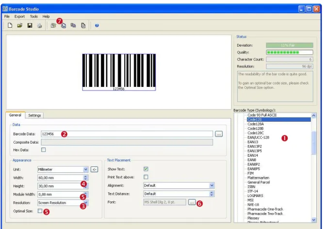
Figure 1: Quick-Start – Barcode Studio Main Window
In order to create an EAN13 bar code, please perform the following steps:
Select the bar code type (symbology) – see section 5.2.1.
Enter the bar code data - see section 5.2.2.
Select the output resolution - see section 5.2.3.
Specify the bar code dimensions - see section 5.2.4.
Fine-tune the module width - see section 5.2.5.
Set font style and size - see section 5.2.6.
Export or print the bar code.
5.2.1 Select Bar Code Type (Symbology)
Select the bar code type (symbology) in . Choose “EAN13” from the list of symbologies.
Hint: If you press the E key, the first entry starting with an “E” will be selected in the list.
5.2.2 Enter Bar Code Data
A valid EAN13 bar code needs exactly 12 digits (or 13 digits including the check digit). Because current data (“123456”) consists only of 6 digits, Barcode Studio informs you with following error message:
Error: Wrong number of input characters (12 chars needed)!
Enter the data to be encoded in . You can also edit the bar code content in the Bar Code Data
dialog or import it from a file (see 7.7.1.1).
The bar code view is updated after every change. If you enter exactly twelve (or thirteen) characters, the bar code will be drawn in the bar code view in the top left corner.
If the input data is invalid (e.g. wrong characters or a wrong number of characters) an error message will be displayed instead of the bar code. For a list of the most common error messages, please refer to Appendix B.
► The 13th digit in the resulting EAN13 bar code (in this case the digit “3”) is the check digit. It will be calculated automatically.
► If you enter 13 (instead of 12) characters you need to provide the correct check digit by yourself. This is not recommended (unless you supply the correct value). A wrong check digit may make the bar code unreadable!
5.2.3 Select Output Resolution
► Barcode Studio uses the selected resolution for computing the barcode images. Thus it is essential to adjust a resolution which leads to readable bar codes (see also section 5.2.5). ► Usually higher resolutions lead to better bar code quality. Please notice that it is very
important that the selected resolution accords to the resolution of the output device (printer, image or of image processing / layout software).
The output resolution can be adjusted in .
In this example the output resolution is changed to “300 dpi”. If you are planning to print the bar code on a laser printer you would most probably select a higher resolution (600 or 1200 dpi).
If you want to export the bar code as image for your web page you could also choose “Screen Resolution” or “72 dpi (BMP)”.
► If you use bar code images in pre-press applications, take care to avoid any scaling or resizing of the generated bar code image. This may lead to inaccuracies and distortions rendering the bar code unusable. Generate the bar code image in exactly the resolution and size as required!
5.2.4 Specify Bar Code Dimensions
The bar code dimensions can be modified by changing width, height, and module width.
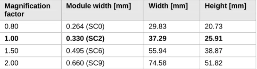
Most label or bar code specifications require specific bar code dimensions. Following values are usual for EAN13:
Magnification factor
Module width [mm] Width [mm] Height [mm]
0.80 0.264 (SC0) 29.83 20.73
1.00 0.330 (SC2) 37.29 25.91
1.50 0.495 (SC6) 55.94 38.87
2.00 0.660 (SC9) 74.58 51.82
Table 1: EAN13 Dimensions (not complete)
Here we use the magnification factor 1.00.
Enter the width and the height in . The appropriate module width will be calculated automatically.
The bar code should now look like this.
5.2.5 Fine-tune the Module Width
Yet the quality of the bar code is not perfect (see the Quality Watch at the top right corner of the Barcode Studio‟s application window):
To optimize the bar code quality we recommend you to fine-tune the module width. You have the following options:
Select the option “Optimal Size” (see Figure 1, )
Choose “Pixel” in field “Unit” and enter a whole-numbered value in the field “Module Width”.
Increase the output resolution
The first two options both lead to a “perfect” bar code quality.
5.2.6 Set Font Style and Size
The font properties can be set via the “Select Font” dialog. You can open this dialog by clicking the button in the “Text Placement” section (see Figure 1 ).
6 Using Bar Codes in Applications
(Exporting Bar Codes)
This chapter is a general instruction for using bar codes generated with Barcode Studio in other applications. A detailed explanation of the user interface and available bar code settings can be found in the next chapter.
6.1 General
You can export the bar codes created in Barcode Studio in the following ways:
Copy the bar code to the clipboard (as image) and paste it into your application.
Copy the bar code to the clipboard (as metafile) and paste it into your application. (available under Microsoft Windows only)
Export the bar code to an image file.
Export a series of bar code images (batch job).
Before the export of a bar code you have to adjust the required bar code settings. The size of the resulting bar code image can be controlled by changing the dimensions (width, height, and module width) and the output resolution (DPI) – see also section 7.7.2 . These settings apply to all kinds of export operations.
6.2 Resolution and Readability
► Do not resize exported bar code images with image manipulation software (like Photoshop®)! The quality and the readability might suffer!
► Whenever possible, let Barcode Studio create the bar code in the required size and resolution to avoid resizing later on.
6.2.1.1 Bar Code Quality
When exporting the bar code to a bitmap image (BMP, GIF, JPG, PNG, and TIF), it must be converted from its internal resolution (high) to a graphical pixel resolution (low). During this process (rasterizing) the module width can vary due to rounding errors.
When exporting a bar code to a vector based image format (EPS, E4C, and E1C) or as metafile to the clipboard, the internal representation of the bar code symbol allows a very high resolution (which is independent of the adjusted dpi). Thus it is recommended to use vector based image formats (EPS, E4C and E1C) whenever possible. However, in the context of certain applications (e.g. web applications) it is inevitable to use bitmap images.
The readability of a bar code can be estimated by looking at the quality watch (see section 7.1, ). The quality of a bar code depends on the selected output resolution, the bar code‟s size and its content. To ensure an optimal readability, check the option “Optimal Size”.
6.2.1.2 Module Width
Larger module widths usually lead to a better readability of a bar code. In practice, for most linear bar codes, the module width should never be less than approximately 0.2 mm.
6.3 Export to File
If you want to export a bar code as an image file, select Export ► Export Barcode… from the menu or press the keyboard shortcut Ctrl+E. In the Save As dialog choose a filename, select the image file type (e.g. “Bitmap (*.bmp)”), and confirm by pressing the Save button.
The saved image can be imported in your target application (e.g. Microsoft® Word). To import the image in Word you would select Insert ► Image ► From File… from the menu.
► The exported bar code symbol will match the preview in Barcode Studio exactly. ► To see a list of available image formats, please refer to Appendix C.
► If the format of the resulting image is a bitmap based file format (see Appendix C), resizing of the imported image is not recommended!
6.4 Copy Barcode to Clipboard
To copy the current bar code as an image to the clipboard, select Copy Barcode to Clipboard from the menu (located in the Export submenu) or from the toolbar. You can also press the keyboard shortcut Ctrl+C.
Then switch to your target application and paste the bar code (e.g. in Microsoft® Word) by pressing Ctrl-V (or by selecting Edit ► Insert from the menu).
► Resizing bar code images may result in a loss of quality. In the worst case resizing a bar code image may lead to unreadable bar codes.
6.5 Copy Metafile to Clipboard
To copy the current bar code as vector based metafile (EMF) to the clipboard select Copy Metafile to Clipboard from the menu (located in the Export submenu) or from the toolbar. You can also press the keyboard shortcut Ctrl+M.
Then switch to your target application and paste the bar code (e.g. in Microsoft® Word) by pressing Ctrl-V (or by selecting Edit ► Insert from the menu).
► Metafiles can only be used on Microsoft Windows.
► Due to the vector based format you may resize the imported image within your target application without heavy losses in readability.
► The resulting bar codes may differ from the preview in Barcode Studio. The bars in the symbol may be enlarged and therefore the font of the human readable text may not fit exactly.
6.6 Export a Series of Bar Codes
For an automated export of a series of bar code images you can use the Create Sequence function. This function is described in chapter 8.
7 Barcode Studio User Interface
7.1 Main Window and Menu
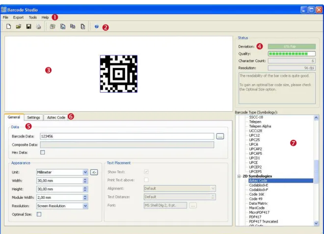
Figure 2: User Interface
The main window is split into the following areas:
Menu (see section 7.2).
Toolbar (see section 7.3).
Barcode View (see section 7.6).
Quality Watch (see section 7.4).
Bar Code Settings (see chapter 7).
Settings for 2D symbologies (according to selected symbology; see section 7.9)
Symbology (see section 7.4).
7.2 Menu
The menu gives you access to the following functions: 7.2.1 File
New Create a new document (with initial bar code settings). Shortcut: Ctrl+N
Open… Open an existing bar code settings document file (*.bc). Shortcut: Ctrl+O
Save as… Save
Save the current bar code settings document file (symbology, dimensions, module width, …). Bar code settings files have the extension .bc.R
Shortcut: Ctrl+S (for Save)
Print… Print the document with current bar code settings.
The output resolution, and so the values for quality and deviation, depend on the printer settings.
Note: Inkjet printers sometimes produce better results if bar width reduction is set (see also section 7.8.1.4).
Shortcut: Ctrl+P
Page Setup… Choose the paper size, the paper source, the orientation, and the page margins.
Exit Exit Barcode Studio. If you have unsaved changes, Barcode Studio will prompt you to save before exiting.
Shortcut: Ctrl+Q
7.2.2 Export
Export Barcode… Export the bar code to a picture file. Shortcut: Ctrl+E
Copy Barcode to Clipboard
Copy the bar code as image to the clipboard. Shortcut: Ctrl+C
Copy Metafile to Clipboard
Copy the bar code as metafile to the clipboard (Windows only). Shortcut: Ctrl+M
Create Sequence… Create a bar code image sequence. Shortcut: Ctrl+U
7.2.3 Tools
Options… Specify the Application‟s Options (see Chapter 9).
7.2.4 Help
Help Open the documentation. Shortcut: F1
TEC-IT Website Open the default browser and navigate to www.tec-it.com. License... Enter your license data.
7.3 Toolbar
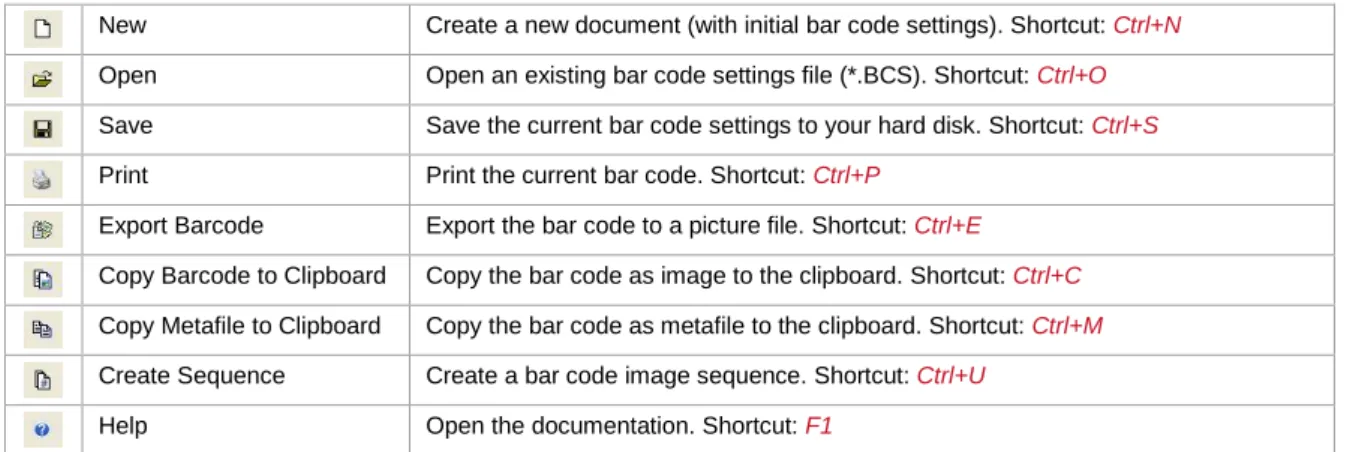
Figure 3: Toolbar
The toolbars offer following functions:
New Create a new document (with initial bar code settings). Shortcut: Ctrl+N
Open Open an existing bar code settings file (*.BCS). Shortcut: Ctrl+O
Save Save the current bar code settings to your hard disk. Shortcut: Ctrl+S
Print Print the current bar code. Shortcut: Ctrl+P
Export Barcode Export the bar code to a picture file. Shortcut: Ctrl+E
Copy Barcode to Clipboard Copy the bar code as image to the clipboard. Shortcut: Ctrl+C
Copy Metafile to Clipboard Copy the bar code as metafile to the clipboard. Shortcut: Ctrl+M
Create Sequence Create a bar code image sequence. Shortcut: Ctrl+U
Help Open the documentation. Shortcut: F1
7.4 Quality Watch – Status Section
Figure 4: Quality Watch
7.4.1 Deviation
The less the deviation the better is the quality and the readability of the bar code. The deviation depends on the output resolution and the print ratio of the bar code. You can also improve the quality by changing the module width to an appropriate value As measurement unit select “Pixel” and set the module width to an integer value (1, 2, 3, …, 25, …).
The Deviation field will report one of the following values: Tolerance Aberration Description
Perfect 0% Optimal output quality.
Fair 1-15% Should be readable with most bar code scanners.
Poor 16-25% May be readable.
Bad! 26-50% Not readable in most cases.
Data Loss! 51-100% Total or partly loss of information. Unreadable bar code.
Table 2: Bar code Qualities
7.4.2 Quality
The quality of the bar code – the higher the deviation, the lower is the quality. 7.4.3 Character Count
Displays the number of characters encoded in the bar code. 7.4.4 Resolution
The current output resolution in dpi (dots per inch). 7.4.5 Hint Box
The hint box () displays information about the current bar code quality and recommended methods to improve the readability.
7.5 Symbology
Select the bar code type (symbology) from the list (see Figure 2, ).
► For 2D codes like Aztec Code, Codablock-F, PDF417, MicroPDF, MaxiCode, Data Matrix, QR Code, GS1-DataBar Stacked variants and for all Composite Symbologies you need a 2D license. For the other symbologies a 1D license is sufficient.
If you want to learn more about the selected symbology, please examine the Barcode Reference
from the Help menu.
7.6 The Bar Code View
Figure 5: Bar Code View
The Bar Code View shows the bar code in its actual appearance (as it is should be printed).
To change the size of the bar code, enter the required dimensions in the “Appearance” section (see section 7.7.2). The quality of the bar code depends on the output resolution and the module width. It can be observed in the Status section (see section 7.4).
7.7 Page General
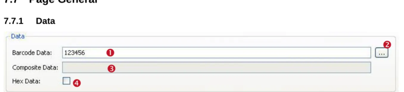
7.7.1 DataFigure 6: Data Section
7.7.1.1 Bar Code Data
Enter the bar code content in the field “Barcode Data” (see ) or in the “Input Data” dialog( ).
Figure 7: Input Data (Dialog)
The Input Data dialog allows you to enter the bar code data in a multi-line edit control and to import the data from a text file via the Load File…. Use the Reset button to clear the Data field.
► Not all bar code types are able to represent all data-characters. Some bar code symbologies can hold digits, others can contain alphanumeric characters (digits + letters + punctuation characters), or the full ASCII character set.
7.7.1.2 Add Control Characters
You can enter control characters directly in the edit field or use the context menu. Open the context menu by right-clicking in the edit field and choose Add Control Characters. Then select the control character, you want to insert, from the submenu.
Figure 8: Add Control Character
Because control characters are represented by special character combinations (like \F for FNC1), Barcode Studio enables escape sequences automatically (see section 7.8.2.3).
For more information on all available control characters, please refer to the “Barcode Reference” available from www.tec-it.com or via the menu Help ► Barcode Reference.
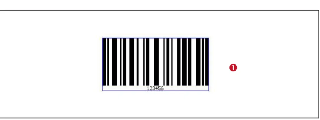
7.7.1.3 Check Digit Override
Some bar codes with a predefined number of utilizable data characters (like all EAN, UPC, Postnet and RSS-14 codes) include a check digit on a fixed position in the bar code data.
Example:
The EAN13 code consists of 12 utilizable digits and 1 check digit at the last position ().
If you enter 12 digits as bar code data the check digit will be
calculated and inserted automatically. However, you can also enter all 13 digits and therefore override the calculated check digit.
► Note: If the bar code data does already contain a check digit, the automatic check digit calculation will be switched off.
► Barcode Studio does not check the correctness of the check digit supplied by your application.
Under normal circumstances you should not use this feature – we recommend relying on the automatic calculation of the check digit(s) by Barcode Studio.
7.7.1.4 Composite Data
The Composite Data field is only enabled if the selected bar code type supports composite data (check if the Composite page is visible) and if a 2D Composite Component has been selected (“Auto”, “CC-A”, “CC-B” or “CC-C”) on this page.
You can also enter the composite data in the Barcode Data field by separating the composite data from the linear bar code data with the vertical bar character "|".
7.7.1.5 Hex Data
If this option has been selected the bar code data is treated as hexadecimal data. This property applies to the bar code data as well as to the composite data.
Whenever Hex Data is enabled Barcode Studio treats manual entered data as well as imported data as a hexadecimal character sequence. This sequence is converted to a normal character sequence before a bar code is generated.
7.7.2 Appearance
7.7.2.1 Unit
This value () specifies the measurement units for displaying and/or entering the dimensions of the bar code. Possible values are:
Millimeter
Inch
Mils (=1/1000 inch)
Pixel.
7.7.2.2 Dimensions (Width, Height)
Use these settings to change the width () and the height () of the bar code.
Unit Description
Millimeter The width and the height of the bar code in millimeters. The physical width (in pixels) can be calculated as follows: width (pixels) = width (mm) / 25.4 * resolution (dpi)
Inch The width and the height of the bar code in inches. The physical width (in pixels) can be calculated as follows: width (pixels) = width (inch) * resolution (dpi)
Mils The width and the height of the bar code in mils.
The physical width (in pixels) can be calculated as follows: width (pixels) = width (mils) / 1000 * resolution (dpi) Pixel The width and the height of the bar code in pixels.
The width and the height are shown as physical (pixel) values. Basis for the displayed dimension is the size on the screen (in mm respectively in inch) and the adjusted resolution (dpi).
Table 3: Units
7.7.2.3 Module Width ()
The bar code is divided into several "modules". A module is the smallest bar (or space) segment. The module width is the fundamental measuring unit for bar codes, i.e. all bar and space widths are based on it.
Normally, the module width is calculated automatically based on the width of the blue bounding rectangle and on the amount of data to be encoded. But it can also be set to a fixed value. Depending upon the screen, printer, or image resolution, the lower limit for the module width may be exceeded. This leads to unreadable bar codes (e.g.: if the module width is smaller than 1 pixel).
MaxiCode: this bar code type has a predefined constant module width to achieve the standard-ized symbol dimensions. However, you can change the module width on demand.
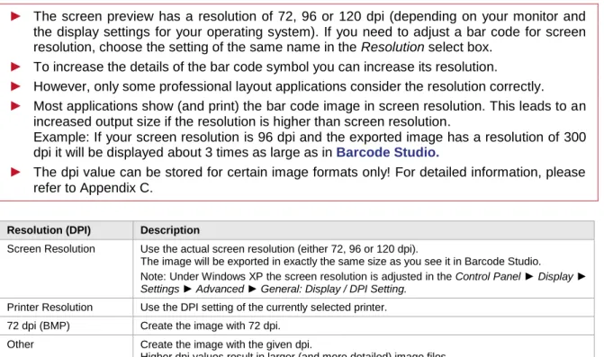
7.7.2.4 Resolution (DPI) ()
► The screen preview has a resolution of 72, 96 or 120 dpi (depending on your monitor and the display settings for your operating system). If you need to adjust a bar code for screen resolution, choose the setting of the same name in the Resolution select box.
► To increase the details of the bar code symbol you can increase its resolution.
► However, only some professional layout applications consider the resolution correctly. ► Most applications show (and print) the bar code image in screen resolution. This leads to an
increased output size if the resolution is higher than screen resolution.
Example: If your screen resolution is 96 dpi and the exported image has a resolution of 300 dpi it will be displayed about 3 times as large as in Barcode Studio.
► The dpi value can be stored for certain image formats only! For detailed information, please refer to Appendix C.
Resolution (DPI) Description
Screen Resolution Use the actual screen resolution (either 72, 96 or 120 dpi).
The image will be exported in exactly the same size as you see it in Barcode Studio. Note: Under Windows XP the screen resolution is adjusted in the Control Panel ► Display ► Settings ► Advanced ► General: Display / DPI Setting.
Printer Resolution Use the DPI setting of the currently selected printer. 72 dpi (BMP) Create the image with 72 dpi.
Other Create the image with the given dpi.
Higher dpi values result in larger (and more detailed) image files.
Table 4: Resolution Settings
When exporting an image to a BMP or to PNG file, the adjusted resolution (dpi) will not be stored there. Only the formats JPG, TIF, and PCX are capable of storing the resolution.
7.7.2.5 Optimal Size
Barcode Studio provides the possibility to enhance the bar code quality and therefore the readability. This setting can be very helpful especially for lower resolutions. If the “Optimal Size” option () is checked, the module width of the bar code will be set to a whole-numbered pixel size (to the nearest lower value). Hereby the pixel deviation is reduced to a minimum or eliminated completely.
In other words: The bar code is printed using whole-numbered pixel sizes only. This avoids aliasing effects and guarantees an optimal scanning quality.
► If the “Optimal Size” option is enabled, the module width will be adjusted for optimum output quality.
► The symbol in the bar code view can only displayed with an optimum size, if the property is set to “Screen Resolution”. The screen preview is not detailed enough to display higher resolutions correctly. You will see the optimal result only on according output devices (printer, image,…).
7.7.2.6 Reset Button
7.7.3 Text Placement
In this section you can change the settings regarding the human readable text of the bar code.
Figure 10: Text Placement Section
7.7.3.1 Show Text
If enabled, the “human readable text“ is displayed. (Default: enabled.)
7.7.3.2 Print Text Above
If enabled, the “human readable text” is printed above the bar code symbol and not below it. (Default: disabled).
This setting cannot be enabled in conjunction with bar code types like UPC and EAN.
7.7.3.3 Alignment
This property adjusts the alignment of the human readable text (Default, Left, Right, and Center).
7.7.3.4 Text Distance
This property adjusts the distance between the “human readable text” and the bar code (in mm).
7.7.3.5 Font
Click the button to select the font used for the human readable text. The selected font is displayed in the text box ().
7.8 Page Settings
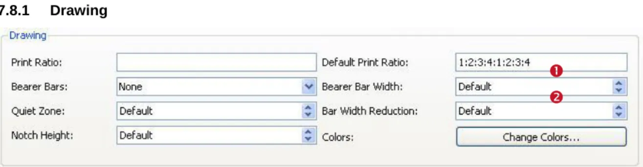
7.8.1 DrawingFigure 11: Drawing Section
7.8.1.1 Print Ratio
The print ratio describes the relationship between the widths of the single bars and spaces of a bar code related to the module width (do not mix up this item with the width/height ratio of a symbol!). The print ratio consists of a colon-separated-list of bar and space widths. The list starts with n bar widths, followed by m space widths. The numbers n and m depend on the bar code type. The width values are not given absolutely but relatively to the module width.
1 “Equal to the module width”,
2 “twice the module width”,
…
You can use the Default Print Ratio as a template for a customized Print Ratio value. It shows how many different bar and space widths are used for the selected bar code type. The absolute width of a bar (or space) is calculated using the values of the print ratio multiplied with the module width. Example: If a bar code element has 4 different bar widths and 4 different space widths, the print ratio could look like this (e.g. for Code 128): 1:2:3:4:1:2:3:4.
The first 4 numbers ("1:2:3:4") stand for the bar widths, in last 4 numbers for the space widths (in this case, they are the same). The smallest bar is "1" module wide, the next larger is "2" (thus twice as wide as the smaller bar) and so on.
► Modifications within this area make sense for special applications only! For the Code 2OF5 interleaved, e.g., the print ratio can range from 1:2 to 1:3.
► Use this option with care! Bar codes may become unreadable when setting wrong print ratios.
For additional information on print ratios, please refer to the “Barcode Reference”.
7.8.1.2 Bearer Bars
Select the kind of bearer bars you want to use. Bearer bars help a decoder to detect the full width of a bar code and reduce the possibility of partial scans (decoding only a part of the symbol). You can change the width of the Bearer Bars in .
7.8.1.3 Quiet Zone
This adjusts the width of the quiet zone around the bar code. The size of the quiet zone is given in a number of modules.
7.8.1.4 Bar Width Reduction
When printing on inkjet printers, the ink that is absorbed by the paper tends to diffuse. Setting the bar width reduction allows you to work against this spreading of ink. But also for laser printers with high toner saturation this property is useful.
The bar width reduction can be specified in percent of the module width. Thus when set to 20 all bars will be narrowed by 20 percent of the module width.
► Be careful: Setting the bar width reduction to more than 50 percent might leave the bar code unreadable! When using this feature we recommend you to do some test-scans to make sure that the bar code can be scanned correctly. A common value to start with is 15%.
7.8.1.5 Notch Height
This property adjusts the height at which the synchronization bars (e.g. the double lines in EAN on the left, center and on the right side) extend the regular bar code height.
7.8.1.6 Colors
Click the Change Colors… button to open the Colors dialog.
Figure 12: Colors Dialog
Click the button beside the color you want to change and select the desired color in the following dialog.
Fore Color: The foreground color of the bar code (color of the bars). Back Color: The background color of the bar code (color of the spaces). Text Color: The color of the “human readable text”.
Back style: Mode for drawing the background of the bar code. The background can be set to transparent (= default, background shines through) or opaque (background is overwritten with the background color). This setting is relevant if you use copy and paste (clipboard).
7.8.2 Advanced Data Manipulation
Figure 13: Advanced Data Manipulation Section
7.8.2.1 Format/Subset
The format string is used for formatting the utilizable data of the bar code according to defined rules. It operates with substitute symbols to indicate how the data shall be structured.
With the format string it is possible to insert constant characters to the bar code data. Control characters make it possible to change the Subsets for Code 128, EAN 128 and UCC 128 or to define the desired start/stop character of CODABAR.
For more information on format strings, please refer to the “Barcode Reference” available from www.tec-it.com or via the menu Help ► Barcode Reference.
7.8.2.2 Check Digit
This property specifies the check digit calculation method. In order to guarantee that the bar code data is going to be read properly a check digit can be added to the end of the utilizable data. A comparison of the bar code content with the check digit informs the scanning device (scanner) about incorrect scans and forces the device to repeat or reject the scan. The check digit calculation method is standardized for certain common bar codes types. Using check digits is mostly optional – but often recommended for particular symbologies and standards.
When set to default the check digit is calculated according to the specification of the selected bar code. Modifications are admissible for bar codes with selectable check digit methods or for special applications only.
For additional information on check digit calculation, please refer to the “Barcode Reference” available from www.tec-it.com or via the menu Help ► Barcode Reference.
7.8.2.3 Escape Sequences
The use of escape sequences is appropriate if you need to encode control characters like carriage return or FNC1 into the bar code.
This option specifies, whether escape sequences (like ”\n”) shall be translated or not (default: no). Each escape sequence starts with a backslash (“\”). For a list of recognized escape sequences, please refer to the additional document “Barcode Reference” available via the menu Help ► Barcode Reference or from www.tec-it.com.
► If escape sequences are activated, the backslash character can‟t be used directly in the bar code data. It must be replaced by a double back-slash “\\” in order to be encoded correctly.
7.9 2D Settings
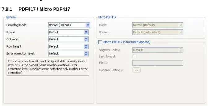
7.9.1 PDF417 / Micro PDF417
Figure 14: PDF417 / Micro PDF417 Properties
The PDF417 / Micro PDF417 page is used to modify the standard behavior of the two-dimensional PDF417 bar codes. PDF417 divides data contents into rows and columns – it is a stacked
7.9.1.1 Encoding Mode
Determine whether to enforce binary encoding. In Binary Encoding mode the encoding algorithm does not try to calculate the smallest possible symbol, but it uses binary encoding for all characters. This is recommended for binary input data and for bar code generation with optimal speed.
7.9.1.2 Rows [3..90]
The number of rows. The value must be between 3 and 90.
Default: the number of lines is calculated automatically depending on the number of input characters.
► This property is not available for the Micro PDF417 symbology!
7.9.1.3 Columns [1..30]
The number of columns. The value must be between 1 and 30. Start-, stop- and line-indicator columns are not taken into account.
Default: the number of columns is calculated automatically depending on the number of input characters.
7.9.1.4 Row Height [mm]
The height of an individual row in millimeter. If specified, the bar code height will remain locked at the specified value. (Modifying the bar code dimensions will only affect the bar code width.).
Default: the row height is calculated automatically depending on the number of input characters.
7.9.1.5 Error Correction Level
The error correction level. The value can be between 0 (only error detection) and 8 (highest correction).
Default: the level is calculated automatically between 2 and 5 - according to the number of input characters.
7.9.1.6 Mode
Specifies how data is encoded as Micro PDF417. In most cases the “Default” mode is the best choice.
► Note: Often the scanner hardware does not support all modes listed here – check with your scanner first.
Mode (Enumeration) Description
Normal (Default) Input data is analyzed. Text, numeric or binary compaction mode will be used according-ly (to produce the smallest symbol).
UCC/EAN-128 Emulation UCC/EAN-128 Emulation mode. Transmit ]C1 or ]L3. Use compaction for Application Identifier (AI) "01" + 14 digits. Code128 Emulation Code-128 Emulation mode. Transmit ]C2 or ]L4.
Code128 FNC2 Emulation Code-128 with FNC2 on first position will be emulated. Linked UCC/EAN-128 Linked UCC/EAN-128 emulation. Transmit ]C1 or ]L3.
Indicates that the Micro PDF symbol is linked with a linear symbol (which may be required for a successful scan).
Using this mode, the following AIs can be encoded with better compaction in the given order:
Date (AI 11, 13, 15 or 17) + lot number (AI 10) + other AI‟s (optional).
Date (AI 11, 13, 15 or 17) + serial number (AI 21) + other AI‟s (optional).
Date (AI 11, 13, 15 or 17) + other AI‟s (optional).
Note: This mode is not used with UCC EAN Composite Symbology, which uses linked symbols, too.
05 Macro The preamble [ ( > RS 0 5 GS precedes the encoded data. 06 Macro The preamble [ ( > RS 0 6 GS precedes the encoded data.
CC-A Data Mode For special applications only: use Base-928 compaction and process input data as byte array.
CC-B Data Mode For special applications only: use binary compaction (Base-900), prefix symbol data with reserved symbology code word.
Table 5: Micro PDF417 - Modes
► This property is not available for the PDF417 symbology!
7.9.1.7 Version
Specifies the “size” of the symbol in terms of codeword-columns and Micro PDF417 rows. ► This property is not available for the PDF417 symbology!
7.9.1.8 Macro PDF417 (Structured Append)
Inserts a Macro PDF control block into the bar code.
PDF417 allows the user to spread the data across several symbols. This might be done if the data is too large to fit into a single symbol or for reasons of appearance and geometry.
The so called “Macro PDF Control Block” carries information that relates its contents to the overall data. The below described properties are mandatory for the Macro PDF functionality.
7.9.1.10 Last Symbol
Identifies the last symbol in the data chain. If set to true, the “Last Segment Indicator” is put at the end of the Macro PDF control block.
7.9.1.11 File ID
The file id identifies all symbols, which belong to the same data chain. For reassembling, all data blocks having the same File ID are concatenated in the order of increasing segment index.
7.9.1.12 Advanced (optional fields)
These fields are optional and may be encoded into the Macro PDF417 control block on demand.
Figure 15: Macro PDF417 Optional Settings
File name (alphanumeric) File name (variable length field).
Segment count (numeric) Total number of data segments (range 1…99999).
Time stamp (numeric) Time stamp (elapsed time in seconds since January 1, 1970 00:00 GMT). Sender (alphanumeric) Sender (variable length field).
Addressee (alphanumeric) Addressee (variable length field).
File size (numeric) Total number of bytes encoded (variable length field).
Checksum (numeric) 16-Bit CRC checksum (using CCITT-16 polynomial x16 + x12 + x5 + 1 over the entire data).
7.9.2 MaxiCode
MaxiCode represents data, by drawing hexagonal items, which are arranged around a circular center (a so called "Bull's Eye"). The internal data structure is regulated by different "modes". The mode "Structured Carrier Message" was defined by the parcel transport service UPS®. Data can be encoded in two different error correction levels (SEC = Standard Error Correction and EEC = Enhanced E.C.).
With “Structured Append” you can divide larger quantities of data into several MaxiCode symbols – they are joined by the scanner. The maximum data capacity of one symbol is 93 characters. The actual quantity of the utilizable data depends on the selected mode, how often special characters are used, whether numeric sequences, which can be compressed, are used and which level of error correction is adjusted.
Figure 16: MaxiCode Properties
7.9.2.1 Mode
Mode (Enumeration) Description
4 – Standard Symbol For numeric and alphanumeric character sequences (incl. standard error correction). 2 – SCM (Numeric) Structured Carrier Message, up to 9 digits (postal code consist of digits only).
3 – SCM (Alphanumeric) Structured Carrier Message, up to 6 characters (postal code consist of alphanumeric characters).
5 – Full EEC Like mode 4 but with enhanced error correction (safer, but fewer utilizable data possible).
Table 6: MaxiCode - Modes
7.9.2.2 Undercut [0..100]
The undercut influences the diameter of the hexagonal bar code elements. In new applications it is recommended (according to the AIM standard) to use an undercut setting of 75% (default).
7.9.2.3 Preamble Options
Used particularly in “Open System Standards”. Under “Preamble Date” the last two digits of a year can be entered. They are inserted automatically into the data stream in a predefined place.
7.9.2.4 Structured Append
If you want to “connect” several MaxiCode symbols in order to encode larger quantities of data, then you can use “Structured Append". A symbol identification number which is entered in the “Index of this Symbol” field can be assigned to each MaxiCode symbol. Its value can range between 1 and 8. This index indicates the order, in which the data is joined after the reading/scanning process. The total number of arranged MaxiCode symbols must be entered in “Number of all symbols”.
7.9.2.5 Structured Carrier Message (SCM)
MaxiCode was originally developed by UPS® (United Parcel Service). In the operating mode "Structured Carrier Message" (mode 2 and 3) there are defined data fields for UPS®-purposes. These can be entered in the fields ”Service Class”, ”Country Code” and ”Postal Code”. In “Mode 3” you can use digits as well as alphanumeric characters for the “Postal Code”.
By using escape sequences it is possible to insert the values for date, preamble, service class, country and postal code directly into the bar code data (text property). To learn more about this possibility, please refer to the additional document “Barcode Reference” available from www.tec-it.com or via the menu Help ► Barcode Reference.
7.9.3 Data Matrix
► Please note, that Barcode Studio always uses ECC 200 error correction.
Figure 17: Data Matrix (ECC200) Properties
7.9.3.1 Code Format
Code Format (Enum.) Description
Default Standard format.
UCC/EAN Special format defined by UCC and EAN. Used for encoding Application Identifiers. (FNC1 at 1st position).
Industry Supports peculiar industry formats (FNC1 at 2nd position). Macro 05 [)>Rs05Gs is encoded at the beginning of the code. Macro 06 [)>Rs06Gs is encoded at the beginning of the code.
Table 7: Data Matrix - Modes
7.9.3.2 Symbol Size
The size of the symbols in number of rows and number of columns. Possible sizes are "10 x 10" to "144 x 144" modules for square symbols and "8 x 18" to "16 x 48" for rectangular symbols. If set to default, the minimal possible square size is used (depending on the input data).
7.9.3.3 Show as Rectangle
Determines if the Data Matrix symbol should be displayed as a rectangle (option is checked) or a square (unchecked - default).
7.9.3.4 Structured Append
If you want to “connect” several Data Matrix symbols in order to encode larger quantities of data, then you can use “Structured Append". A symbol identification number - which is entered in the “Index of this Symbol” field - can be assigned to each Data Matrix symbol. Its value can range from 1 to 16. This index indicates the order, in which the data is joined after the reading/scanning process. The total number of arranged Data Matrix symbols must be entered in “Number of all symbols”. The “File ID” has to be the same for all symbols within such a chain.
7.9.4 QR-Code
The QR Code symbology is a 2-dimensional matrix symbology (similar to Data Matrix). Remarkable is the large data capacity (up to 3000 ASCII characters or 7000 digits). QR Code means Quick Readable code – it was originally designed to read and decode symbols with high amounts of data within a minimum of time.
Figure 18: QR-Code Properties
7.9.4.1 Format / Application Indicator
Format (Enum.) Description
Default Standard format.
UCC/EAN Special format defined by UCC and EAN. Used for encoding Application Identifiers. (FNC1 at 1st position).
Industry For special industry formats (FNC1 is inserted at second position). If you choose this value, you also have to fill in the field Application Indicator (2 digits or 1 letter). It determines to which industry format the input data (should) correspond(s).
Table 8: QR Code - Modes
7.9.4.2 Symbol Version (Size)
Specifies the version (= size) of the QR Code symbol, defined by a version number, the number of rows and the number of columns. Possible values range from „(1) 21 x 21" up to „(40) 177 x 177"
7.9.4.3 Error Correction Level
Defines the error correction level. You can choose from following possible values: Error Correction Level
(Enum.)
Description
(L)ow Lowest level. Data recovery capacity is up to approximately 7%.
(M)edium (default) Up to 15%.
(Q)uartil Up to 25%.
(H)igh Highest level. Up to 30%.
Table 9: QR Code – Error Correction Levels
7.9.4.4 Mask Pattern
Specifies the mask pattern that is applied to the symbol to improve readability. Mask Pattern (Enum.) Description
Default The mask pattern is calculated automatically.
0..7 With the values 0 to 7 you choose the appropriate mask pattern. It would make sense to specify this setting directly, especially, if you have to optimize computation time. The algorithm to calculate the optimal mask is rather complex (and therefore very resource consuming).
Table 10: QR Code – Mask Patterns
7.9.4.5 Compaction
The MultiByte compaction mode. QR Code provides code compaction for various MultiByte character encodings (Kanji, Chinese). This compaction can help to produce smaller bar codes.
Compaction (Enum.) Description Default multi byte compaction
(Default)
Automatically chooses the appropriate compaction method. No multi byte compaction Disables the multi byte compaction.
Kanji character compaction Enables the compaction for Kanji characters. Chinese character compaction Enables the compaction for Chinese characters.
Table 11: QR Code – Compaction
QR-Code supports compaction of Kanji characters (if present in the MultiByte character set Shift JIS X 0208). The Kanji characters are compacted into a 12-Bit codeword (instead of a 2 Byte / 16 Bit codeword) – so you need less space in the symbol. It is recommended to enable this compaction only if you have Kanji characters in your input data. Enabling is not recommended for binary data.
7.9.4.6 Structured Append
If you want to “connect” several QR Code symbols in order to encode larger quantities of data, then you can use “Structured Append". A symbol identification number which is entered in the “Index of this Symbol” field can be assigned to each QR Code symbol. Its value can range from 1 to 16. This index indicates the order, in which the data is joined after the reading/scanning process. The total number of arranged symbols must be entered in “Number of all Symbols”.
Chained QR Code symbols are identified by the parity byte. The parity byte must be identical in all symbols. The value can be calculated using the method „QR_StructAppParity“, which is part of TBarCode.
7.9.5 Aztec Code
Figure 19: Aztec Code Properties
7.9.5.1 Format / Format Specifier
Code Format (Enum.) Description
Default Standard format.
UCC/EAN Special format defined by UCC and EAN. Used for encoding Application Identifiers. (FNC1 at 1st position).
Industry For special industry formats (FNC1 is inserted at second position). If you choose this value, you also have to fill in the field Application Indicator (2 digits or 1 letter). It determines to which industry format the input data (should) correspond(s).
Table 12: Aztec Code – Modes
7.9.5.2 Symbol Size
Defines the size of the Aztec Code symbol by the number of rows and the number of columns. Possible values range from „15 x 15" up to „151 x 151" modules. If the property is set to default, the size is computed automatically based on the data to be encoded.
7.9.5.3 Enforce Binary Encoding
Determine whether to enforce binary encoding. In Binary Encoding mode the encoding algorithm does not try to calculate the smallest possible symbol, but it uses binary encoding for all characters. This is recommended for binary input data and for bar code generation with optimal speed.
7.9.5.4 Aztec Runes Mode
Enables the Aztec Runes mode. Aztec Runes are a special kind of Aztec Code Symbols and are used to generate small and very fast readable markers. Aztec Runes can only encode integer values from 0 to 255.
7.9.5.5 Error Correction
Defines the error correction level. The value can be between 1 and 89 percent. Default: the level is set to 23 percent.
7.9.5.6 Structured Append
If you want to “connect” several Aztec Code symbols in order to encode larger quantities of data, then you can use “Structured Append". A symbol identification number which is entered in the “Index of this Symbol [A..Z]” field can be assigned to each Aztec Code symbol. Its value can range from “A” to “Z”. This index indicates the order, in which the data is joined after the reading/scanning process. The index of the last Symbol must be entered in “Number of all Symbols [A..Z]”.
Chained Aztec Code symbols are identified by the “Message ID”. The “Message ID” must be identical in all symbols.
7.9.6 Codablock-F
The Codablock-F property page is used to adjust symbology specific parameters. Similar to PDF-417 the data content is divided into rows and columns. Codablock-F is a stacked symbology with additional internal checksums for error recognition.
Codablock-F is based upon the Code 128 symbology - one data row consists of a single Code 128 bar code extended with row identifiers and column check sum. This page is not relevant to other symbologies.
► Caution when modifying these adjustments. Always make a test scan in case of doubt!
Figure 20: Codablock-F Properties
7.9.6.1 Code Format
Code Format (Enum.) Description
Standard Standard format
UCC/EAN Special format defined by UCC and EAN to be used in UCC/EAN applications.
Table 13: Codablock-F – Modes
7.9.6.2 Rows [2..44]
The number of rows used for encoding. The value must be between 2 and 44. Default: the number of lines is calculated automatically depending on the number of input characters.
7.9.6.3 Columns [4..62]
The number of columns (data words), which are to be printed. The value must be between 4 and 62. Start-, stop- and line-indicator columns are not taken into account. Default: the number of columns is calculated automatically depending on the number of input characters.
7.9.6.4 Row Height [mm]
The height of an individual row in millimeter. If specified, the bar code height will remain locked at the specified value. (Modifying the bar code dimensions will only affect the bar code width.) Default: the row height is calculated automatically depending on the number of input characters.
7.9.6.5 Separator Height [mm]
The width of the row separator line in millimeter. Default: the line width is equal to the module width (calculated automatically depending on the symbol size).
7.9.7 Composite Symbology
Figure 21: Composite Symbology Settings
Composite components are available for the following bar codes:
EAN8
EAN13
GS1-DataBar / RSS14
GS1 DataBar Stacked / RSS14 Stacked
GS1 DataBar Stacked Omnidirectional / RSS14 Stacked Omnidirectional
GS1 DataBar Truncated / RSS14 Truncated
GS1 DataBar Expanded / RSS Expanded
GS1 DataBar Expanded Stacked / RSS Expanded Stacked
GS1 DataBar / RSS Limited
GS1-128 / UCC/EAN128
UPC-A
UPC-E
7.9.7.1 2D Composite Component
None Composite Symbologies are disabled.
Auto Automatically choose CC-A, CC-B or CC-C Symbology depending on the length of the input data. CC-A CC-A is a variant of the MicroPDF417 Symbol with a unique combination of row address patterns
(RAP). It is the smallest variant of the 2-dimensional composite component. Up to 56 digits of alphanumeric data can be coded with 3 to 12 rows and 4 columns.
CC-B CC-B is a subset of the MicroPDF417 Symbol, which is identified by the code word 920. Encoding systems choose CC-B automatically when CC-A has not enough capacity (Auto-mode). CC-B encodes up to 338 digits of alphanumeric data in 3 to 12 rows and 2 to 4 columns.
CC-C The CC-C structure is a PDF417 Symbol, which is identified by the internal code word 920 (920 is the first code word after the symbol length indicator). The CC-C structure can be used as a 2 dimensional composite component of a UCC/EAN-128 Composite Symbols. It has the largest data capacity of EAN.UCC Composite Symbols because of its possibility to code of up to 2361 numbers. It can code numbers with up to 2361 digits of alphanumeric data, which have 3 to 30 rows and up to 30 Data-Error-checking-Code-Columns.
7.9.7.2 Segments per Row
This property adjusts the number of (graphical data) segments per row in the GS1 DataBar Expanded Stacked (RSS) Symbol. This parameter influences the width of the bar code. “Default”
means that each row contains at least 4 segments.
8 Sequences
8.1 General
The sequence functionality can be used to generate a series of bar code images. The data for the sequence can be generated automatically or imported from files.
Select Export ► Create Sequence... from the menu to open the following dialog or use the keyboard shortcut Ctrl+U:
8.2 Sequence Export
Figure 22: Sequence Export
The sequence list shows a preview of the bar code data strings. For each line in the list a bar code image file will be generated. The file names are based upon a prefix, the item value (=bar code data) and the file extension.
For populating this list you can
Create a sequence () or
Import a sequence () from a text file.
With the button you can export the bar code images (see section 8.2.3). 8.2.1 Create Sequence
8.2.1.1 Start Value
Defines the start value for the sequence. Must be smaller than the end value.
8.2.1.2 End Value
Defines the end value for the sequence. Must be bigger than the start value.
8.2.1.3 Increment
This value specifies the incremental steps between consecutive list items.
► The last value of the generated sequence will never exceed the number specified in End Value.
8.2.1.4 Format
The Format defines the format pattern, which will be applied to all items of the sequence. The format string may contain 3 special characters, the placeholders, which are replaced by the sequence number. All other characters stay as they are:
Character Description
# Barcode Studio inserts leading blanks instead of the placeholders if the number of characters given in Format string exceeds the number of characters in the item of the sequence.
$ Like “#” but insert leading zeros instead of blanks. * Like “#” but insert leading stars instead of blanks.
All other characters are used literally.
Table 14: Format - Characters
Examples: Format String
Sample Output Description
$$ 01, 02, 03, …, 10, 11 Leading zeros
## 1, 2, 3, …, 10, 11 Leading spaces
** *1, *2, *3, …, 10, 11 Leading asterisks
00$$ 0001, 0002, 0003, …, 0099 Like “$$” but with “00” as constant prefix
A$$ A01, A02, A03,… Like “$$” but with “A” as constant prefix
Table 15: Format - Examples
► If you enter “$$$” and create a sequence containing numeric values higher than 999, the bar code data will be truncated. In this case change the format string.
8.2.1.5 Create
Based on the settings specified above create the sequence. Click Create to start. 8.2.2 Import Sequence
In order to import the sequence data from a file click the Import… button.
In the appearing dialog you can specify the file to be imported. Suggested file types are *.txt, *.csv, *.tab and *.tsv files. Each line of the file will be imported as value of the item list.
It is possible to specify the names of the exported images in the import file. To do this you have to prefix each data line with the file name followed by a column separator. Column separators may be commas, semicolons, spaces or tabs. See also chapter 8.2.3 Export Bar Codes.
8.2.3 Export Bar Codes
The Export… button opens a separate dialog in which you can choose the path (where to store the exported image files), the prefix of the file name (may be empty), the filename generation method and the image file format. Each item in the sequence list produces exactly one image file.
Figure 23: Export Bar Codes from Sequence
You have several options to generate a file name: Generation Method Description
Same as Data The file name is based on the bar code data (sequence data). For instance if you encode “12345” in the bar code, the file name will be prefix + 12345.bmp. Ideal for numeric values and for easy bar code to image file assignment.
Note: if the sequence data contains characters that are not allowed for file names, use the following method.
Same as Data (URL Escaped)
The same as “Data” but characters which are not allowed in a file names or URLs are escaped by a percent sign followed by the hexadecimal ASCII code.
\ %5C / %2F : %3A
* %2A ? %3F “ %22
< %3C > %3E | %7C
% %25
First Data Column The first column of the input data (sequence data) contains the file name.
This option should be used with import files, where the first column of each data line contains the file name. Field separators in the sequence data are: comma, semicolon, space and tab.
Serial Number The image file names are based on serial numbers starting with 1.
Formatted Serial Number Same as Serial Number but the numbers are prefixed with leading zeros. E.g. if you have 100 bar codes you will get 001, 002, 003 … 100.
Table 16: Sequence – File Name
If at least one image file cannot be generated, the export function will be terminated. This may have one of the following reasons:
A value of the sequence item list cannot be encoded by the actual selected bar code type (e.g.: symbology 2of5 IL may only contain digits).
An invalid file name has been generated (e.g. if you have a backslash in the data and “Data URL-Escaped” is not used).
Keep in mind that exporting many sequence items can take a lot of time and hard drive space! ► If you import your values from an external file and the values to be encoded are varying in
9 Options
In the Options dialog you can change general settings.
You can open the Options dialog via the menu Tools ► Options…
Figure 24: Options Dialog
9.1 Output
9.1.1 Draw ModeTo handle different printer driver implementations, you are able to choose from several draw modes.
Draw Mode Description Default
Advanced
The bar codes are drawn in the advanced mode. This provides the best quality.
Compatible The bar codes are drawn in the compatible mode. This decreases the quality slightly, but is supported by the most printers.
Dual The bar codes are drawn in the dual mode. This is a combination of the Advanced and Compatible mode.
Table 17: Draw Modes
9.2 Font Substitution for EPS Export
Font Substitution is only used when exporting the barcode to an EPS file. This is an advanced option and should only be changed for special applications.
9.2.1 Font Substitution
Specifies the font substitution method that is used for EPS export. Font Substitution Description
None The font won‟t be substituted, unless it is a invalid one Automatic (Default) The font will always be substituted with an appropriate one.
Fixed Font The font will always be substituted with the font specified in “Surrogate Font”
Table 18: Font Substitution
9.2.2 Surrogate Font
The font used for EPS exports. This property overrides the “Font” property on the “General” tab, but only if “Font Substitution” () is set to “Fixed Font”.