Conference Bridge setup
This chapter provides information to configure conference bridges using Cisco Unified Communications Manager Administration.
See the following for additional information:
• Conference bridges and trusted relay points in theCisco Unified Communications Manager System Guide
• Configuring Secure Conference Bridge in Cisco Unified Communications Manager Administration,
Cisco Unified Communications Manager Features and Services Guide.
• Cisco Unified Communications Manager Administration Guide for Cisco Unified Communications Manager Business Edition 5000
• Configuring Secure Conference Bridge in Cisco Unified Communications Manager Administration,
Cisco Unified Communications Manager Security Guide
•Cisco Unified Videoconferencing 3511 MCU and Cisco Unified Videoconferencing 3540 MCU Module Administrator Guide
•Cisco Unified Serviceability Administration Guide
• About conference bridge setup, page 1
• Conference Bridge deletion, page 2
• Conference Bridge settings, page 2
• Set up TLS connection with Cisco TelePresence MCU, page 23
• Synchronize conference device settings, page 24
About conference bridge setup
In Cisco Unified Communications Manager Administration, use theMedia Resources>Conference Bridge menu path to configure conference bridges.
Conference bridge configuration tips
Make sure that the following prerequisites are met before you proceed with configuration of a conference bridge:
• Configure the device pools.
Software conference bridges automatically get created when the Cisco Unified Communications Manager server gets created. You cannot add software conference bridges to Cisco Unified Communications Manager Administration.
Note
• For software conference bridges, activate the Cisco IP Voice Media Streaming Application service. See theCisco Unified Serviceability Administration Guide.
Related Topics
Device pool deletion
Software Conference Bridge settings, on page 3 Synchronize conference device settings, on page 24
Conference Bridge deletion
Keep in mind that you cannot delete Cisco Unified Communications Manager Conference Bridge Software. Cisco Unified Communications Manager allows you to delete devices that may be associated with components such as media resource groups. To find out what dependencies the conference device may have, choose the Dependency Records link from the drop-down list box and click Go from the Conference Bridge Configuration window. If the dependency records are not enabled for the system, the dependency records summary window displays a message.
Related Topics
Access dependency records
Conference Bridge settings
Consult the conference bridge configuration settings table that corresponds to the type of conference bridge that you are configuring.
Related Topics
Software Conference Bridge settings, on page 3 Hardware Conference Bridge settings, on page 5 Cisco IOS Conference Bridge settings, on page 7 Cisco Video Conference Bridge settings, on page 9
Cisco Conference Bridge (WS-SVC-CMM) settings, on page 11
Conference Bridge setup Conference Bridge deletion
Cisco IOS Homogeneous Video Conference Bridge settings, on page 17 Cisco TelePresence MCU settings, on page 19
Software Conference Bridge settings
Conference Bridge for Cisco Unified Communications Manager, a software or hardware application, allows both ad hoc and meet-me voice conferencing. Each conference bridge can host several simultaneous, multiparty conferences.
Be aware that both hardware and software conference bridges can be active at the same time. Software and hardware conference devices differ in the number of streams and the types of codec that they support. You cannot add software conference bridges to Cisco Unified Communications Manager by using Conference Bridge Configuration. Software conference bridges automatically get added when a Cisco Unified
Communications Manager server gets added. After a Cisco Unified Communications Manager server gets added, the software conference bridge gets displayed in the Find/List Conference Bridges window (by default, the first software conference bridge gets configured during Cisco Unified Communications Manager installation) when you perform a search. You can update software conference bridges, but you cannot delete them. See theCisco Unified Communications Manager System Guidefor more information about conference bridges. The following table describes the software conference bridge configuration settings.
Table 1: Software conference bridge configuration settings
Description Field
This field automatically displays Cisco Conference Bridge Software. Conference
Bridge Type
This field automatically displays the Cisco Unified Communications Manager server for this software conference bridge.
Host Server
This field automatically displays the software conference bridge name. The format of the name specifies CFB_ followed by a digit that represents the value of the software conference bridge; for example, CFB_3 represents the third conference bridge in the Cisco Unified Communications Manager system.
Conference Bridge Name
This field automatically displays a description, but the administrator can update this field. Description
Choose a device pool that has the highest priority within the Cisco Unified Communications Manager group that you are using or choose Default.
Device Pool
Choose the common device configuration to assign to the conference bridge. The common device configuration includes attributes, such as MOH audio source, that support features and services for phone users.
Device configurations that are configured in the Common Device Configuration window display in the drop-down list.
Common Device Configuration
Conference Bridge setup
Description Field
Use locations to implement call admission control (CAC) in a centralized call-processing system. CAC enables you to regulate audio quality and video availability by limiting the amount of bandwidth that is available for audio and video calls over links between locations. The location specifies the total bandwidth that is available for calls to and from this location.
From the drop-down list box, choose the appropriate location for this conference bridge. A location setting of Hub_None means that the locations feature does not keep track of the bandwidth that this conference bridge consumes. A location setting of Phantom specifies a location that enables successful CAC across intercluster trunks that use H.323 protocol or SIP.
To configure a new location, use theSystem>Locationmenu option.
For an explanation of location-based CAC across intercluster trunks, see theCisco Unified Communications Manager System Guide.
Location
From the drop-down list box, enable or disable whether Cisco Unified CM inserts a trusted relay point (TRP) device with this media endpoint. Choose one of the following values:
• Default—If you choose this value, the device uses the Use Trusted Relay Point setting from the common device configuration with which this device associates. • Off—Choose this value to disable the use of a TRP with this device. This setting overrides the Use Trusted Relay Point setting in the common device configuration with which this device associates.
• On—Choose this value to enable the use of a TRP with this device. This setting overrides the Use Trusted Relay Point setting in the common device configuration with which this device associates.
A Trusted Relay Point (TRP) device designates an MTP or transcoder device that is labeled as Trusted Relay Point.
Cisco Unified CM places the TRP closest to the associated endpoint device if more than one resource is needed for the endpoint (for example, a transcoder or RSVPAgent). If both TRP and MTP are required for the endpoint, TRP gets used as the required MTP. See topics related to TRP insertion in Cisco Unified Communications Manager in the
Cisco Unified Communications Manager System Guidefor details of call behavior. If both TRP and RSVPAgent are needed for the endpoint, Cisco Unified CM first tries to find an RSVPAgent that can also be used as a TRP.
If both TRP and transcoder are needed for the endpoint, Cisco Unified CM first tries to find a transcoder that is also designated as a TRP.
See topics related to trusted relay points and media resource management in theCisco Unified Communications Manager System Guidefor a complete discussion of network virtualization and trusted relay points.
Use Trusted Relay Point
Conference Bridge setup Software Conference Bridge settings
Hardware Conference Bridge settings
Conference Bridge for Cisco Unified Communications Manager, a software or hardware application, allows both ad hoc and meet-me voice conferencing. Each conference bridge can host several simultaneous, multiparty conferences.
Be aware that both hardware and software conference bridges can be active at the same time. Software and hardware conference devices differ in the number of streams and the types of codec that they support.
The hardware model type for Conference Bridge contains a specific Media Access Control (MAC) address and device pool information.
Note
See theCisco Unified Communications Manager System Guidefor more information about conference bridges. The following table describes the hardware conference bridge configuration settings.
Table 2: Hardware conference bridge configuration settings
Description Field
Choose Cisco Conference Bridge Hardware.
For a description of this type, see theCisco Unified Communications Manager System Guide.
Conference Bridge Type
Enter a unique device MAC address in this required field. MAC addresses comprise 12 hexadecimal digits (0-9, A-F).
Example 1231123245AB MAC Address
This field automatically generates from the MAC address that you provide. You can update this field if you choose.
Description
Choose a device pool that has the highest priority within the Cisco Unified Communications Manager group that you are using or choose Default.
Device Pool
Choose the common device configuration to assign to the conference bridge. The common device configuration includes attributes, such as MOH audio source, that support features and services for phone users.
Device configurations that are configured in the Common Device Configuration window display in the drop-down list.
Common Device Configuration
Conference Bridge setup
Description Field
Use locations to implement call admission control (CAC) in a centralized call-processing system. CAC enables you to regulate audio quality and video availability by limiting the amount of bandwidth that is available for audio and video calls over links between locations. The location specifies the total bandwidth that is available for calls to and from this location.
From the drop-down list box, choose the appropriate location for this conference bridge. A location setting of Hub_None means that the locations feature does not keep track of the bandwidth that this conference bridge consumes. A location setting of Phantom specifies a location that enables successful CAC across intercluster trunks that use H.323 protocol or SIP.
To configure a new location, use theSystem>Locationmenu option.
For an explanation of location-based CAC across intercluster trunks, see theCisco Unified Communications Manager System Guide.
Location
From the drop-down list box, enable or disable whether Cisco Unified CM inserts a trusted relay point (TRP) device with this media endpoint. Choose one of the following values:
• Default—If you choose this value, the device uses the Use Trusted Relay Point setting from the common device configuration with which this device associates. • Off—Choose this value to disable the use of a TRP with this device. This setting overrides the Use Trusted Relay Point setting in the common device configuration with which this device associates.
• On—Choose this value to enable the use of a TRP with this device. This setting overrides the Use Trusted Relay Point setting in the common device configuration with which this device associates.
A Trusted Relay Point (TRP) device designates an MTP or transcoder device that is labeled as Trusted Relay Point.
Cisco Unified CM places the TRP closest to the associated endpoint device if more than one resource is needed for the endpoint (for example, a transcoder or RSVPAgent). If both TRP and MTP are required for the endpoint, TRP gets used as the required MTP. See theCisco Unified Communications Manager System Guidefor details of call behavior. If both TRP and RSVPAgent are needed for the endpoint, Cisco Unified CM first tries to find an RSVPAgent that can also be used as a TRP.
If both TRP and transcoder are needed for the endpoint, Cisco Unified CM first tries to find a transcoder that is also designated as a TRP.
See theCisco Unified Communications Manager System Guidefor a complete discussion of network virtualization and trusted relay points.
Use Trusted Relay Point
Enter any special load information or leave blank to use default. Special Load
Information
Conference Bridge setup Hardware Conference Bridge settings
Related Topics
Cisco IOS Conference Bridge settings
Conference Bridge for Cisco Unified Communications Manager, a software or hardware application, allows both ad hoc and meet-me voice conferencing. Each conference bridge can host several simultaneous, multiparty conferences.
Be aware that both hardware and software conference bridges can be active at the same time. Software and hardware conference devices differ in the number of streams and the types of codec that they support. See theCisco Unified Communications Manager System Guidefor more information about conference bridges. The following table describes the Cisco IOS conference bridge configuration settings.
Table 3: Cisco IOS conference bridge configuration settings
Description Field
Choose Cisco IOS Conference Bridge or Cisco IOS Enhanced Conference Bridge. For a description of these types, see theCisco Unified Communications Manager System Guide.
Conference Bridge Type
Enter the same name that exists in the gateway Command Line Interface (CLI). You can enter up to 15 characters. Valid characters comprise alphanumeric characters (a-z, A-Z, 0-9), as well as dot (.), dash (-),and underscore (_).
Conference Bridge Name
This field automatically generates from the conference bridge name that you provide. You can update this field if you choose.
Description
Choose a device pool or choose Default. Device Pool
Choose the common device configuration to assign to the conference bridge. The common device configuration includes attributes, such as MOH audio source, that support features and services for phone users.
Device configurations that are configured in the Common Device Configuration window display in the drop-down list.
Common Device Configuration
Conference Bridge setup
Description Field
Use locations to implement call admission control (CAC) in a centralized call-processing system. CAC enables you to regulate audio quality and video availability by limiting the amount of bandwidth that is available for audio and video calls over links between locations. The location specifies the total bandwidth that is available for calls to and from this location.
From the drop-down list box, choose the appropriate location for this conference bridge. A location setting of Hub_None means that the locations feature does not keep track of the bandwidth that this conference bridge consumes. A location setting of Phantom specifies a location that enables successful CAC across intercluster trunks that use H.323 protocol or SIP.
To configure a new location, use theSystem>Locationmenu option.
For an explanation of location-based CAC across intercluster trunks, see theCisco Unified Communications Manager System Guide.
Location
This field displays for Cisco IOS Enhanced Conference Bridge only.
If you choose Non Secure Conference Bridge, the nonsecure conference establishes a TCP port connection to Cisco Unified Communications Manager on port 2000.
Ensure this setting matches the security setting on the conference bridge, or the call will fail.
Tip
The Encrypted Conference Bridge setting supports the secure conference feature. See the
Cisco Unified Communications Manager System Guidefor secure conference bridge configuration procedures.
Device Security Mode
Conference Bridge setup Cisco IOS Conference Bridge settings
Description Field
From the drop-down list box, enable or disable whether Cisco Unified CM inserts a trusted relay point (TRP) device with this media endpoint. Choose one of the following values:
• Default—If you choose this value, the device uses the Use Trusted Relay Point setting from the common device configuration with which this device associates. • Off—Choose this value to disable the use of a TRP with this device. This setting overrides the Use Trusted Relay Point setting in the common device configuration with which this device associates.
• On—Choose this value to enable the use of a TRP with this device. This setting overrides the Use Trusted Relay Point setting in the common device configuration with which this device associates.
A Trusted Relay Point (TRP) device designates an MTP or transcoder device that is labeled as Trusted Relay Point.
Cisco Unified CM places the TRP closest to the associated endpoint device if more than one resource is needed for the endpoint (for example, a transcoder or RSVPAgent). If both TRP and MTP are required for the endpoint, TRP gets used as the required MTP. See theCisco Unified Communications Manager System Guidefor details of call behavior. If both TRP and RSVPAgent are needed for the endpoint, Cisco Unified CM first tries to find an RSVPAgent that can also be used as a TRP.
If both TRP and transcoder are needed for the endpoint, Cisco Unified CM first tries to find a transcoder that is also designated as a TRP.
See theCisco Unified Communications Manager System Guidefor a complete discussion of network virtualization and trusted relay points.
Use Trusted Relay Point
Related Topics
Cisco Video Conference Bridge settings
Conference Bridge for Cisco Unified Communications Manager, a software or hardware application, allows both ad hoc and meet-me voice conferencing. Each conference bridge can host several simultaneous, multiparty conferences.
Be aware that both hardware and software conference bridges can be active at the same time. Software and hardware conference devices differ in the number of streams and the types of codec that they support. See theCisco Unified Communications Manager System Guidefor more information about conference bridges. The following table describes the Cisco video conference bridge configuration settings.
Conference Bridge setup
Table 4: Cisco video conference bridge configuration settings
Description Field
Choose Cisco Video Conference Bridge (IPVC-35xx).
For a description of this type, see theCisco Unified Communications Manager System Guide.
Conference Bridge Type
Enter a unique device MAC address in this required field. MAC addresses comprise 12 hexadecimal digits (0-9, A-F).
Example 1231123245AB MAC Address
This field automatically generates from the conference bridge name that you provide. You can update this field if you choose.
Description
Choose a device pool or choose Default. Device Pool
Choose the common device configuration to assign to the conference bridge. The common device configuration includes attributes, such as MOH audio source, that support features and services for phone users.
Device configurations that are configured in the Common Device Configuration window display in the drop-down list.
Common Device Configuration
Use locations to implement call admission control (CAC) in a centralized call-processing system. CAC enables you to regulate audio quality and video availability by limiting the amount of bandwidth that is available for audio and video calls over links between locations. The location specifies the total bandwidth that is available for calls to and from this location.
From the drop-down list box, choose the appropriate location for this conference bridge. A location setting of Hub_None means that the locations feature does not keep track of the bandwidth that this conference bridge consumes. A location setting of Phantom specifies a location that enables successful CAC across intercluster trunks that use H.323 protocol or SIP.
To configure a new location, use theSystem>Locationmenu option.
For an explanation of location-based CAC across intercluster trunks, see theCisco Unified Communications Manager System Guide.
Location
Conference Bridge setup Cisco Video Conference Bridge settings
Description Field
From the drop-down list box, enable or disable whether Cisco Unified CM inserts a trusted relay point (TRP) device with this media endpoint. Choose one of the following values:
• Default—If you choose this value, the device uses the Use Trusted Relay Point setting from the common device configuration with which this device associates. • Off—Choose this value to disable the use of a TRP with this device. This setting overrides the Use Trusted Relay Point setting in the common device configuration with which this device associates.
• On—Choose this value to enable the use of a TRP with this device. This setting overrides the Use Trusted Relay Point setting in the common device configuration with which this device associates.
A Trusted Relay Point (TRP) device designates an MTP or transcoder device that is labeled as Trusted Relay Point.
Cisco Unified CM places the TRP closest to the associated endpoint device if more than one resource is needed for the endpoint (for example, a transcoder or RSVPAgent). If both TRP and MTP are required for the endpoint, TRP gets used as the required MTP. See theCisco Unified Communications Manager System Guidefor details of call behavior. If both TRP and RSVPAgent are needed for the endpoint, Cisco Unified CM first tries to find an RSVPAgent that can also be used as a TRP.
If both TRP and transcoder are needed for the endpoint, Cisco Unified CM first tries to find a transcoder that is also designated as a TRP.
See theCisco Unified Communications Manager System Guidefor a complete discussion of network virtualization and trusted relay points.
Use Trusted Relay Point
Product-Specific Configuration
The device manufacturer specifies the model-specific fields under product-specific configuration. Because they are dynamically configured, they can change without notice. To view field descriptions and help for product-specific configuration items, click the “?” information icon under the Product Specific Configuration heading to display help in a popup dialog box.
If you need more information, see the documentation for the specific device that you are configuring or contact the manufacturer.
Model-specific configuration fields that the device manufacturer defines
Related Topics
Cisco Conference Bridge (WS-SVC-CMM) settings
Conference Bridge for Cisco Unified Communications Manager, a software or hardware application, allows both ad hoc and meet-me voice conferencing. Each conference bridge can host several simultaneous, multiparty conferences.
Conference Bridge setup
Be aware that both hardware and software conference bridges can be active at the same time. Software and hardware conference devices differ in the number of streams and the types of codec that they support. See theCisco Unified Communications Manager System Guidefor more information about conference bridges. The following table describes the Cisco Conference Bridge (WS-SVC-CMM) configuration settings. Table 5: Cisco conference bridge (WS-SVC-CMM) configuration settings
Description Field
Choose Cisco Conference Bridge (WS-SVC-CMM).
For a description of this type, see theCisco Unified Communications Manager System Guide.
Conference Bridge Type
Enter a description (up to 50 characters) or leave blank to generate automatically from the MAC address that you provide. Invalid characters comprise quotes (“), angle brackets (<>), backslash (), ampersand,(&), and percent sign (%).
Description
Enter a unique device MAC address in this required field. MAC addresses comprise 12 hexadecimal digits (0-9, A-F).
Example 1231123245AB MAC Address
From the drop-down list box, choose the value for the daughter card for a given slot on the Communication Media Module card.
Subunit
Choose a device pool or choose Default. Device Pool
Choose the common device configuration to assign to the conference bridge. The common device configuration includes attributes, such as MOH audio source, that support features and services for phone users.
Device configurations that are configured in the Common Device Configuration window display in the drop-down list.
Common Device Configuration
Use locations to implement call admission control (CAC) in a centralized call-processing system. CAC enables you to regulate audio quality and video availability by limiting the amount of bandwidth that is available for audio and video calls over links between locations. The location specifies the total bandwidth that is available for calls to and from this location.
From the drop-down list box, choose the appropriate location for this conference bridge. A location setting of Hub_None means that the locations feature does not keep track of the bandwidth that this conference bridge consumes. A location setting of Phantom specifies a location that enables successful CAC across intercluster trunks that use H.323 protocol or SIP.
To configure a new location, use theSystem>Locationmenu option. Location
Conference Bridge setup Cisco Conference Bridge (WS-SVC-CMM) settings
Description Field
From the drop-down list box, enable or disable whether Cisco Unified CM inserts a trusted relay point (TRP) device with this media endpoint. Choose one of the following values:
• Default—If you choose this value, the device uses the Use Trusted Relay Point setting from the common device configuration with which this device associates. • Off—Choose this value to disable the use of a TRP with this device. This setting overrides the Use Trusted Relay Point setting in the common device configuration with which this device associates.
• On—Choose this value to enable the use of a TRP with this device. This setting overrides the Use Trusted Relay Point setting in the common device configuration with which this device associates.
A Trusted Relay Point (TRP) device designates an MTP or transcoder device that is labeled as Trusted Relay Point.
Cisco Unified CM places the TRP closest to the associated endpoint device if more than one resource is needed for the endpoint (for example, a transcoder or RSVPAgent). If both TRP and MTP are required for the endpoint, TRP gets used as the required MTP. See theCisco Unified Communications Manager System Guidefor details of call behavior. If both TRP and RSVPAgent are needed for the endpoint, Cisco Unified CM first tries to find an RSVPAgent that can also be used as a TRP.
If both TRP and transcoder are needed for the endpoint, Cisco Unified CM first tries to find a transcoder that is also designated as a TRP.
See theCisco Unified Communications Manager System Guidefor a complete discussion of network virtualization and trusted relay points.
Use Trusted Relay Point
Choose the maximum number of streams for a given service on a daughter card. Possible values include 32, 64, 96, and 128 streams. Ensure that each daughter card has as many ports as the value that you choose.
Maximum Capacity
Product-Specific Configuration
To view field descriptions and help for product-specific configuration items, click the “?” information icon under the Product Specific Configuration heading to display help in a popup dialog box.
If you need more information, see the documentation for the specific device that you are configuring or contact the manufacturer.
Model-specific configuration fields that the device manufacturer defines
Conference Bridge setup
Related Topics
Cisco IOS Heterogeneous Video Conference Bridge settings
Cisco Integrated Services Routers Generation 2 (ISR G2) can act as IOS-based conference bridges that support ad hoc and meet-me video conferencing. DSP modules must be installed on the router to enable the router as a conference bridge.
Cisco IOS Heterogeneous Video Conference Bridge specifies the IOS-based conference bridge type that supports heterogeneous video conferences. In a heterogeneous video conference, all the conference participants connect to the conference bridge with phones that use different video format attributes. In heterogeneous conferences, transcoding and transsizing features are required from the DSP to convert the signal between the various formats.
For heterogeneous video conferences, callers connect to the conference as audio participants under either of the following conditions:
• Insufficient DSP resources.
• The conference bridge is not configured to support the video capabilities of the phone.
See theCisco Unified Communications Manager System Guidefor more information about conference bridges. The following table describes the Cisco IOS Heterogeneous Video Conference Bridge configuration settings. Table 6: Cisco IOS heterogeneous video conference bridge settings
Description Field
Enter a name for your conference bridge. Conference
Bridge Name
Enter a description for your conference bridge Description
Choose a device pool or choose Default. Device Pool
Choose the common device configuration to assign to the conference bridge. The common device configuration includes attributes, such as MOH audio source, that support features and services for phone users.
Device configurations that are configured in the Common Device Configuration window display in the drop-down list.
Common Device Configuration
Conference Bridge setup Cisco IOS Heterogeneous Video Conference Bridge settings
Description Field
Use location to implement call admission control (CAC) in a centralized call-processing system. CAC enables you to regulate audio quality and video availability by limiting the amount of bandwidth that is available for audio and video calls over links between locations. The location specifies the total bandwidth that is available for calls to and from this location.
From the drop-down list box, choose the appropriate location for this conference bridge. A location setting of Hub_None means that the locations feature does not keep track of the bandwidth that this conference bridge consumes. A location setting of Phantom specifies a location that enables successful CAC across intercluster trunks that use H.323 protocol or SIP.
To configure a new location, use theSystem>Locationmenu option.
For an explanation of location-based CAC across intercluster trunks, see theCisco Unified Communications Manager System Guide.
Location
From the drop-down list box, enable or disable whether Cisco Unified CM inserts a trusted relay point (TRP) device with this media endpoint.
• Default—If you choose this value, the device uses the Use Trusted Relay Point setting from the common device configuration with which this device associates. • Off—Choose this value to disable the use of a TRP with this device. This setting overrides the Use Trusted Relay Point setting in the common device configuration with which this device associates.
• On—Choose this value to enable the use of a TRP with this device. This setting overrides the Use Trusted Relay Point setting in the common device configuration with which this device associates.
A Trusted Relay Point (TRP) device designates an MTP or transcoder device that is labeled as Trusted Relay Point.
Cisco Unified CM places the TRP closest to the associated endpoint device if more than one resource is needed for the endpoint (for example, a transcoder or RSVPAgent). If both TRP and MTP are required for the endpoint, TRP gets used as the required MTP. See theCisco Unified Communications Manager System Guidefor details of call behavior. If both TRP and RSVPAgent are needed for the endpoint, Cisco Unified CM first tries to find an RSVPAgent that can also be used as a TRP.
If both TRP and transcoder are needed for the endpoint, Cisco Unified CM first tries to find a transcoder that is also designated as a TRP.
See theCisco Unified Communications Manager System Guidefor a complete discussion of network virtualization and trusted relay points.
Use Trusted Relay Point
Conference Bridge setup
Related Topics
Cisco IOS Guaranteed Audio Video Conference Bridge settings
Cisco Integrated Services Routers Generation 2 (ISR G2) can act as IOS-based conference bridges that support ad hoc and meet-me voice and video conferencing. DSP modules must be installed on the router to enable the router as a conference bridge.
Cisco IOS Guaranteed Audio Video Conference Bridge specifies the IOS-based video conference bridge type where DSP resources are reserved for the audio portion of the conference, and video service is not guaranteed. Callers on video phones may have video service if DSP resources are available at the start of the conference. Otherwise, the callers connect to the conference as audio participants.
See theCisco Unified Communications Manager System Guidefor more information about conference bridges. The following table describes the Cisco IOS Heterogeneous Video Conference Bridge configuration settings. Table 7: Cisco IOS guaranteed audio video conference bridge settings
Description Field
Enter a name for your conference bridge Conference
Bridge Name
Enter a description for your conference bridge Description
Choose a device pool or choose Default. Device Pool
Choose the common device configuration to assign to the conference bridge. The common device configuration includes attributes, such as MOH audio source, that support features and services for phone users.
Device configurations that are configured in the Common Device Configuration window display in the drop-down list.
Common Device Configuration
Use location to implement call admission control (CAC) in a centralized call-processing system. CAC enables you to regulate audio quality and video availability by limiting the amount of bandwidth that is available for audio and video calls over links between locations. The location specifies the total bandwidth that is available for calls to and from this location.
From the drop-down list box, choose the appropriate location for this conference bridge. A location setting of Hub_None means that the locations feature does not keep track of the bandwidth that this conference bridge consumes. A location setting of Phantom specifies a location that enables successful CAC across intercluster trunks that use H.323 protocol or SIP.
To configure a new location, use theSystem>Locationmenu option.
For an explanation of location-based CAC across intercluster trunks, see theCisco Unified Communications Manager System Guide.
Location
Conference Bridge setup Cisco IOS Guaranteed Audio Video Conference Bridge settings
Description Field
From the drop-down list box, enable or disable whether Cisco Unified CM inserts a trusted relay point (TRP) device with this media endpoint.
• Default—If you choose this value, the device uses the Use Trusted Relay Point setting from the common device configuration with which this device associates. • Off—Choose this value to disable the use of a TRP with this device. This setting overrides the Use Trusted Relay Point setting in the common device configuration with which this device associates.
• On—Choose this value to enable the use of a TRP with this device. This setting overrides the Use Trusted Relay Point setting in the common device configuration with which this device associates.
A Trusted Relay Point (TRP) device designates an MTP or transcoder device that is labeled as Trusted Relay Point.
Cisco Unified CM places the TRP closest to the associated endpoint device if more than one resource is needed for the endpoint (for example, a transcoder or RSVPAgent). If both TRP and MTP are required for the endpoint, TRP gets used as the required MTP. See theCisco Unified Communications Manager System Guidefor details of call behavior. If both TRP and RSVPAgent are needed for the endpoint, Cisco Unified CM first tries to find an RSVPAgent that can also be used as a TRP.
If both TRP and transcoder are needed for the endpoint, Cisco Unified CM first tries to find a transcoder that is also designated as a TRP.
See theCisco Unified Communications Manager System Guidefor a complete discussion of network virtualization and trusted relay points.
Use Trusted Relay Point
Related Topics
Cisco IOS Homogeneous Video Conference Bridge settings
Cisco Integrated Services Routers Generation 2 (ISR G2) can act as IOS-based conference bridges that support ad hoc and meet-me video conferencing. DSP modules must be installed on the router to enable the router as a conference bridge.
Cisco IOS Homogeneous Video Conference Bridge specifies the IOS-based conference bridge type that supports homogeneous video conferences. A homogeneous video conference is a video conference in which all participants connect using the same video format attributes. All the video phones support the same video format and the conference bridge sends the same data stream format to all the video participants.
If the conference bridge is not configured to support the video format of a phone, the caller on that phone connects to the conference as an audio only participant.
See theCisco Unified Communications Manager System Guidefor more information about conference bridges. The following table describes the Cisco IOS Homogeneous Video Conference Bridge configuration settings.
Conference Bridge setup
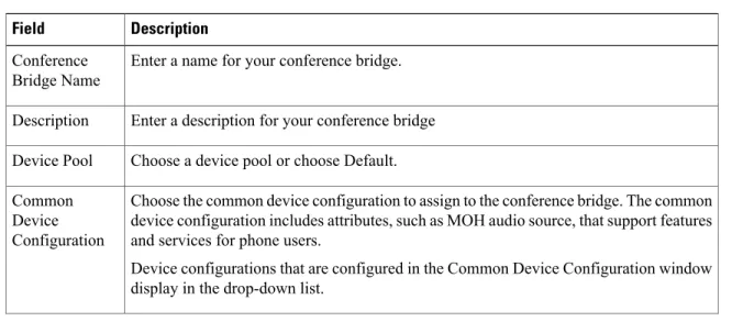
Table 8: Cisco IOS homogeneous video conference bridge settings
Description Field
Enter a name for your conference bridge. Conference
Bridge Name
Enter a description for your conference bridge Description
Choose a device pool or choose Default. Device Pool
Choose the common device configuration to assign to the conference bridge. The common device configuration includes attributes, such as MOH audio source, that support features and services for phone users.
Device configurations that are configured in the Common Device Configuration window display in the drop-down list.
Common Device Configuration
Use location to implement call admission control (CAC) in a centralized call-processing system. CAC enables you to regulate audio quality and video availability by limiting the amount of bandwidth that is available for audio and video calls over links between locations. The location specifies the total bandwidth that is available for calls to and from this location.
From the drop-down list box, choose the appropriate location for this conference bridge. A location setting of Hub_None means that the locations feature does not keep track of the bandwidth that this conference bridge consumes. A location setting of Phantom specifies a location that enables successful CAC across intercluster trunks that use H.323 protocol or SIP.
To configure a new location, use theSystem>Locationmenu option.
For an explanation of location-based CAC across intercluster trunks, see theCisco Unified Communications Manager System Guide.
Location
Conference Bridge setup Cisco IOS Homogeneous Video Conference Bridge settings
Description Field
From the drop-down list box, enable or disable whether Cisco Unified CM inserts a trusted relay point (TRP) device with this media endpoint.
• Default—If you choose this value, the device uses the Use Trusted Relay Point setting from the common device configuration with which this device associates. • Off—Choose this value to disable the use of a TRP with this device. This setting overrides the Use Trusted Relay Point setting in the common device configuration with which this device associates.
• On—Choose this value to enable the use of a TRP with this device. This setting overrides the Use Trusted Relay Point setting in the common device configuration with which this device associates.
A Trusted Relay Point (TRP) device designates an MTP or transcoder device that is labeled as Trusted Relay Point.
Cisco Unified CM places the TRP closest to the associated endpoint device if more than one resource is needed for the endpoint (for example, a transcoder or RSVPAgent). If both TRP and MTP are required for the endpoint, TRP gets used as the required MTP. See theCisco Unified Communications Manager System Guidefor details of call behavior. If both TRP and RSVPAgent are needed for the endpoint, Cisco Unified CM first tries to find an RSVPAgent that can also be used as a TRP.
If both TRP and transcoder are needed for the endpoint, Cisco Unified CM first tries to find a transcoder that is also designated as a TRP.
See theCisco Unified Communications Manager System Guidefor a complete discussion of network virtualization and trusted relay points.
Use Trusted Relay Point
Related Topics
Cisco TelePresence MCU settings
Cisco TelePresence MCU refers to a set of hardware conference bridges for Cisco Unified Communications Manager.
The Cisco TelePresence MCU is a high-definition (HD) multipoint video conferencing bridge. It delivers up to 1080p at 30 frames per second, full continuous presence for all conferences, full trans-coding, and is ideal for mixed HD endpoint environments.
The Cisco TelePresence MCU supports SIP as the signaling call control protocol. It has a built in Web Server that allows for complete configuration, control and monitoring of the system and conferences. The Cisco TelePresence MCU provides XML management API over HTTP.
Cisco TelePresence MCU allows both ad hoc and meet-me voice and video conferencing. Each conference bridge can host several simultaneous, multiparty conferences.
See theCisco Unified Communications Manager System Guidefor more information about conference bridges. The following table describes the Cisco TelePresence MCU configuration settings.
Conference Bridge setup
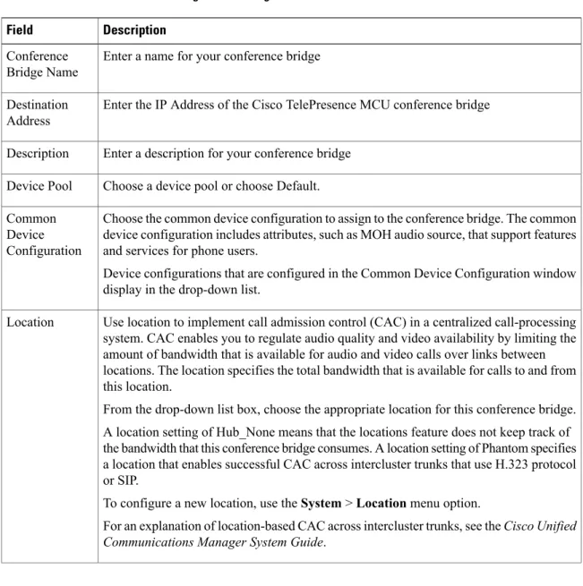
Table 9: Cisco TelePresence MCU configuration settings
Description Field
Enter a name for your conference bridge Conference
Bridge Name
Enter the IP Address of the Cisco TelePresence MCU conference bridge Destination
Address
Enter a description for your conference bridge Description
Choose a device pool or choose Default. Device Pool
Choose the common device configuration to assign to the conference bridge. The common device configuration includes attributes, such as MOH audio source, that support features and services for phone users.
Device configurations that are configured in the Common Device Configuration window display in the drop-down list.
Common Device Configuration
Use location to implement call admission control (CAC) in a centralized call-processing system. CAC enables you to regulate audio quality and video availability by limiting the amount of bandwidth that is available for audio and video calls over links between locations. The location specifies the total bandwidth that is available for calls to and from this location.
From the drop-down list box, choose the appropriate location for this conference bridge. A location setting of Hub_None means that the locations feature does not keep track of the bandwidth that this conference bridge consumes. A location setting of Phantom specifies a location that enables successful CAC across intercluster trunks that use H.323 protocol or SIP.
To configure a new location, use theSystem>Locationmenu option.
For an explanation of location-based CAC across intercluster trunks, see theCisco Unified Communications Manager System Guide.
Location
Conference Bridge setup Cisco TelePresence MCU settings
Description Field
From the drop-down list box, enable or disable whether Cisco Unified CM inserts a trusted relay point (TRP) device with this media endpoint.
• Default—If you choose this value, the device uses the Use Trusted Relay Point setting from the common device configuration with which this device associates. • Off—Choose this value to disable the use of a TRP with this device. This setting overrides the Use Trusted Relay Point setting in the common device configuration with which this device associates.
• On—Choose this value to enable the use of a TRP with this device. This setting overrides the Use Trusted Relay Point setting in the common device configuration with which this device associates.
A Trusted Relay Point (TRP) device designates an MTP or transcoder device that is labeled as Trusted Relay Point.
Cisco Unified CM places the TRP closest to the associated endpoint device if more than one resource is needed for the endpoint (for example, a transcoder or RSVPAgent). If both TRP and MTP are required for the endpoint, TRP gets used as the required MTP. See theCisco Unified Communications Manager System Guidefor details of call behavior. If both TRP and RSVPAgent are needed for the endpoint, Cisco Unified CM first tries to find an RSVPAgent that can also be used as a TRP.
If both TRP and transcoder are needed for the endpoint, Cisco Unified CM first tries to find a transcoder that is also designated as a TRP.
See theCisco Unified Communications Manager System Guidefor a complete discussion of network virtualization and trusted relay points.
Use Trusted Relay Point
SIP Interface Info
This is the SIP listening port of the Cisco TelePresence MCU Conference Bridge. The default value is 5060.
MCU Conference Bridge SIP Port
From the drop-down list box, chooseStandard SIP Profile for TelePresence Conferencing.
SIP Profile
Conference Bridge setup
Description Field
From the drop-down list box, choose the security profile to apply to the SIP trunk. You must apply a security profile to all SIP trunks. Cisco Unified Communications Manager provides a default nonsecure SIP trunk security profile for autoregistration. To enable security features for a SIP trunk, configure a new security profile and apply it to the SIP trunk. If the trunk does not support security, choose a nonsecure profile. To identify the settings that each profile contains, choose System > Security Profile > SIP Trunk Security Profile.
If you are using SRTP with Cisco TelePresence MCU, the SIP trunk security profile must use the following settings:
• Device Security Mode must be Encrypted
• Incoming Transport Type and Outgoing Transport Type must be TLS
• X.509 Subject Name must be set to the defined Common Name used in the Cisco TelePresence MCU certificates
For information on how to configure security profiles, see the Cisco Unified Communications Manager Security Guide.
SIP Trunk Security Profile
Check the SRTP Allowed check box if you want Cisco Unified Communications Manager to allow secure and nonsecure calls with Cisco TelePresence MCU.
If you do not check this check box, Cisco Unified Communications Manager prevents SRTP negotiation with the Cisco TelePresence MCU and uses RTP instead.
For more information on encryption, see theCisco Unified Communications Manager Security Guide.
When this check box is checked, the vcs-interop script is selected by default in the Script drop-down list box and the Enable Trace check box is checked. Note
If you check this check box, you must configure TLS so that you do not expose keys and other security-related information during call negotiations.
Note SRTP Allowed
Normalization Script info
From the drop-down list box, choose the script that you want to apply to the Cisco TelePresence MCU.
To import another script, go to the SIP Normalization Script Configuration window (Device >Device Settings>SIP Normalization Script), and import a new script file.
Script
Check this check box to enable tracing within the script or uncheck this check box to disable tracing. When checked, the trace.output API provided to the Lua scripter produces an SDI trace.
Cisco recommends that you enable tracing only while debugging a script. Tracing has an impact on performance and should not be enabled under normal operating conditions.
Note Enable Trace
Conference Bridge setup Cisco TelePresence MCU settings
Description Field
Optionally, enter parameter names and parameter values. Valid values include all characters except equal signs (=), semicolons (;), and nonprintable characters, such as tabs. You can enter a parameter name with no value.
Example
Parameter Name Parameter Value CCA-ID 11223344
pbx
location RTP
You must choose a script from the Normalization Script drop-down list box before you can enter parameter names and values.
To add another parameter line, click the + (Plus) button. To delete a parameter line, click the – (Minus) button.
Parameter Name/Parameter Value
HTTP Interface Info
Enter the Cisco TelePresence MCU administrator username. Username
Enter the Cisco TelePresence MCU administrator password. Password
Enter the Cisco TelePresence MCU administrator password Confirm
Password
Enter the Cisco TelePresence MCU HTTP port. The default port is 80. HTTP Port
Check this check box if you want to create a secure HTTPS connection between Cisco Unified Communications Manager and Cisco TelePresence MCU. The default HTTPS port is 443.
For information on how to create a TLS connection between Cisco Unified
Communications Manager and Cisco TelePresence MCU, see the Set up a TLS connection with Cisco TelePresence MCU section.
Use HTTPS
The HTTP configuration must match what is configured on the Cisco TelePresence MCU. This information allows Cisco Unified Communications Manager to invoke the remote management API on the Cisco TelePresence MCU.
Note
Related Topics
Set up TLS connection with Cisco TelePresence MCU
If you are using SRTP with Cisco TelePresence MCU, you must set up a TLS connection with Cisco TelePresence MCU so that you do not expose keys and other security-related information during call negotiations.
Conference Bridge setup
This procedure details tasks that are performed in Cisco Unified Communications Manager. For detailed instructions on how to import and export certificates in Cisco TelePresence MCU, see your Cisco TelePresence MCU product documentation.
Note
Procedure
Step 1 Download the Cisco Unified Communications Manager security certificate by performing the following steps: a) In Cisco Unified Operating System Administration, chooseSecurity>Certificate Management. b) ClickFind.
c) ClickCallManager.pemto view the certificate. d) ClickDownloadand save the file to a local drive.
Step 2 Upload the Cisco Unified Communications Manager certificate to Cisco TelePresence MCU.
Step 3 Generate self-signed certificates for Cisco TelePresence MCU and save the certificates to a local drive.
Step 4 Upload self-signed certificates to the Cisco TelePresence MCU.
Step 5 Upload Cisco TelePresence MCU certificates to Cisco Unified Communications Manager by doing the following:
a) In Cisco Unified Operating System Administration, chooseSecurity>Certificate Management. b) ClickUpload Certificate/Certificate Chain.
c) From the Certificate Name drop-down list box, chooseCallManager-trust.
d) ClickBrowseand locate the Cisco TelePresence MCU certificate that you saved locally. e) ClickUpload Fileto upload certificates.
Step 6 In Cisco Unified Communications Manager Administration, chooseSystem>Security>SIP Trunk Security Profileand create a secure SIP Trunk Security Profile that uses the following settings:
• Device Security Mode must be Encrypted
• Incoming Transport Type and Outgoing Transport Type must be TLS
• X.509 Subject Name must be set to the defined Common Name that is used in the Cisco TelePresence MCU certificates
Step 7 On the Cisco TelePresence MCU, configure SIP signaling encryption with TLS, and media encryption with SRTP.
Related Topics
Synchronize conference device settings
To synchronize a conference device with the most recent configuration changes, perform the following
Conference Bridge setup Synchronize conference device settings
Procedure
Step 1 ChooseMedia Resources>Conference Bridge. The Find and List Conference Bridges window displays.
Step 2 Choose the search criteria to use.
Step 3 Click Find.
The window displays a list of conference bridges that match the search criteria.
Step 4 Check the check boxes next to the conference bridges that you want to synchronize. To choose all conference bridges in the window, check the check box in the matching records title bar.
Step 5 Click Apply Config to Selected.
The Apply Configuration Information dialog displays.
Step 6 Click OK.
Related Topics
Conference Bridge setup
Conference Bridge setup Synchronize conference device settings