http://www.sciencepublishinggroup.com/j/ajetm doi: 10.11648/j.ajetm.20180303.12
ISSN: 2575-1948 (Print); ISSN: 2575-1441 (Online)
Motion Analysis and Optimization Design of Back Support
Mechanism Based on Pose Adjustment
Yibo Liu, Ying Pan
College of Mechanical Engineering, Shanghai University of Engineering Science, Shanghai, China
Email address:
To cite this article:
Yibo Liu, Ying Pan. Motion Analysis and Optimization Design of Back Support Mechanism Based on Pose Adjustment. American Journal of Engineering and Technology Management. Vol. 3, No. 3, 2018, pp. 47-53. doi: 10.11648/j.ajetm.20180303.12
Received: July 4, 2018; Accepted: July 17, 2018; Published: August 8, 2018
Abstract:
In order to realize stable and safe operation of multi-mode bed back support mechanism, various angle adjustment mechanisms are studied and analyzed. An angle adjustment mechanism using a guide mechanism is proposed. The function of back support is achieved by using an electric push rod. A model of the back support mechanism was built. Based on the analysis of the geometric relationship and mechanical model of the back support mechanism, the optimal solution of the fixed position of the electric actuator was solved by using MATLAB. Dynamic simulation, performed by SOLIDWORKS Motion, determine the optimal stroke of the electric actuator. Finite element analysis, performed by SOLIDWORKS Simulation, verify the feasibility of the back support mechanism. The simulation results show that using the back support mechanism of the guide rod mechanism reduces the load of the load beam, improves the safety of the back support mechanism, and stabilizes the back support process.Keywords:
Multi-modal Bed, Back Support Mechanism, Dynamic Simulation, Finite Element Analysis1. Introduction
China is a world's most populous country. According to relevant investigations, the aging of China’s society is becoming more and more serious. The issue of old-age care has become a worry for the country and the people [1]. In view of the mobility-impaired elderly people who are cared for by their families or carers, and rely mostly on labor, labor intensity, and low comfort for the elderly, ancillary care equipment came into being [2]. According to different sources of power, auxiliary care equipment can be divided into manual and electric [3]. The function of back support can realize the change of position and posture from lying down to sitting, saving manpower and improving the user's somatosensory comfort.
The commonly used back support mechanism includes a crank slider mechanism, a gear set mechanism, and a guide rod mechanism [4]. The back-support mechanism based on the crank slider mechanism uses human or motor as the power source, and the screw rotates to drive the slider and the linkage mechanism connected with the slider to perform movement to complete the angle adjustment. However, this mechanism has many hinge points, high failure rate, low reliability, and a large space [5]. The back-support mechanism based on the gear group mechanism can achieve larger angle adjustment, but the
gear lubrication requirements are high, and the tooth surface is prone to pitting and other damage [6]. The back-support mechanism based on the guide rod mechanism has few hinge points, simple mechanism and high reliability [7].
Under the above background, a back-support mechanism using a guide rod mechanism is proposed. the guide rod mechanism in the multi-modal bed is an electric push rod. A back support mechanism model of the electric stroke of different strokes is constructed to determine the best fixed position of each electric push rod. During the back-support movement, the angular velocity of the backboard assembly, the force of the electric push rod, the bearing capacity of the hinge, the comfort and other factors are analyzed, and the fixed position and stroke of the electric push rod are determined to optimize the back-support mechanism.
2. Overall Layout Design
support and complete multi-modal seat bed mode to seat mode change. The process is reversible. The functions of multi-modal bed mainly include the form of multi-modal seat, the docking and separation of the bed frame, the back-support function, the leg bending function, the walking function and so on.
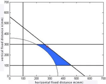
The back support mechanism is as shown in Figure 2. One end of the electric push rod 2 is fixed on the electric push rod fixing beam 1 by a hinge, and the other end is fixed on the back hinge fixing beam 3 by a hinge. The telescopic movement of the electric push rod drives the rotation of the back bed plate assembly around the hinge to complete the back support function.
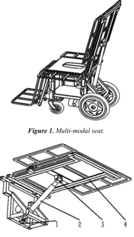
Figure 1. Multi-modal seat.
Figure 2. Back support mechanism.
1. Electric push rod fixing beam 2. Electric push rod 3. Back hinge fixing beam 4. Back bed assembly
3. Back Support Mechanism Mechanical
Model
According to the multi-mode bed use conditions and related standards, determine the multi-mode bed part of the size shown in Table 1. The size of the fixed length n in the vertical direction of the electric push rod is limited by the total height of the multi-mode bed and the size of the motor.
Table 1. Back support mechanism size parameter (mm).
Back bed assembly length L
Total height of multimodal bed
Electric push rod fixed height n
730 530 300
Figure 3 is a schematic diagram of the back-support mechanism. The back-bed assembly can be rotated around the hinge A, and θ is the angle between the back-bed assembly
and the horizontal direction. θmin=0° and θmax=80° are
determined according to functional requirements. B and C are the hinge points of the electric push rod, the back bed assembly and the back hinge fixed beam. β is the angle between the electric push rod and the horizontal direction. m is the horizontal dimension of the hinge A and the hinge B, and n is the vertical dimension of the hinge A and the hinge C. With reference to ergonomics data, the upper body weight accounts for 62% of the body weight of 110kg [8-9]. The back bedplate assembly weight is 7.9Kg.W is the back bedplate assembly tolerance, the force role radius r = 367.06mm. The length of the electric push rod is l.
Figure 3. Mechanism Sketch.
The geometric relationship of the parameters of the back support mechanism shown in Figure 3:00
2 2
l= m +n +2m n sim⋅ ⋅ θ (1)
2 2
sin sin( )
2 sin
n m
m n m n
θ β
θ + ⋅
=
+ + ⋅ ⋅ ⋅ (2)
4. Electric Push Rod Force Solution
Assume that the electric push rod force is F, the displacement of the electric push rod in the force F direction is dl, and the displacement of the back bed plate assembly bearing force W in the vertical direction is dh. Known by the principle of virtual work:
dh
W⋅ = ⋅F dl (3)
The back board assembly can be rotated around the hinge A, transforming (3) to:
r sin
W⋅ ⋅ θ θ⋅d = ⋅F dl (4)
Bring the geometric parameters of the mechanism into equation (4)
2 2
r tan 2 sin
W m n m n
F
m n
θ θ
⋅ ⋅ ⋅ + + ⋅ ⋅ ⋅
=
According to equation (5), the factors affecting the force F of the electric push rod are m, n, and θ. When the fixed position of the electric push rod is determined, m and n are determined. When the back support angle θ is increased from 0° to 80°, m2+n2+2·m·n·sinθ increases as θ increases. From this we know that (5) the increase or decrease is consistent with θ. When the back branch is at the same angle, but the fixed distances m and n are not the same, the actuator force F of the electric actuator is different. The influence of m and n on the force F is analyzed. The formula (5) is used to derive the derivative of θ:
2 2
2 2 2
d tan cos
2 sin
sec 2
F W r
d m n m n
W r m n m n sim
m n θ θ θ θ θ θ ⋅ ⋅ ⋅ = + + + ⋅ ⋅ ⋅ ⋅ ⋅ ⋅ + + ⋅ ⋅ ⋅ ⋅ (6)
If (6) is greater than 0, then:
3 2 2
sin
θ
− + ⋅ ⋅ ⋅(1 2 m n) sinθ
−m − ≤n 0 (7)Equation (7) is taken as the equation for sin θ, and the Shengjin formula knows that the system of equations has a single solution but only one real solution.
1 2
1
( )
3
X = − Y +Y (8)
Among them:
1 2
3
1 2
Y = υ υ+
1 2
3
2 2
Y = υ υ−
2 2
1 27 (m n )
υ = ⋅ +
2 2 3
2 3 81 m n 12(1 2 m n)
υ = ⋅ (⋅ + )− + ⋅ ⋅
X is a number less than 0, that is, regardless of the values of m and n, the maximum value of the electric pusher force F will appear at the maximum angle of the back support. The radius of action of the force is r=367.06mm, the maximum angle of the back support mechanism is 80°, W is 1100N, and the above data is brought into equation (5), F is a function of m and n:
2 2
228987.1 1.96 .
m n m n
F
m n
θ = + + ⋅ ⋅ (9)
5. The Optimal Solution of the Fixed
Position of the Electric Actuator
The back support mechanism can use different strokes of the electric push rod, but the corresponding fixed positions of the electric push rods are different. Therefore, the strength and direction of the back bed plate assembly and the electric push rod are different, and the back support angular velocity which is directly related to the comfort is different. With m, n and electric push rod installation length and maximum size as the boundary conditions, find the feasible field of different stroke electric push rods. Use Equation (9) as the objective function to find the optimal solution.
Table 2. Boundary conditions (mm).
Maximum length of electric push rod installation length horizontal installation size M vertical installation size n
160+2s 160+s 100-700 100-300
Where s is the electric actuator stroke, s=100+50i (i=1, 2, 3, 4), when the electric actuator stroke is larger, the back bed assembly boundary is exceeded. According to the actual running condition of the electric push rod, the B hinge point should always be on the right side of the C hinge point.
The geometry before the back support function is not performed:
2 2 2
(160 )
m +n ≥ +s (10)
The geometric relationship when completing the back support function:
2 2 2
(n m+ ⋅sin )
θ
+ ⋅(m cos )θ
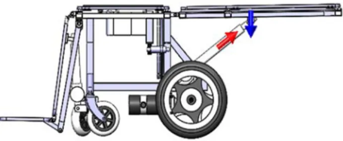
≤(160 2 )+ s (11)According to the above constraints, draw feasible regions in MATLAB, as shown in Figure 4.
b). Electric push rod stroke is 200, m, n feasible region
c). Electric push rod stroke is 250, m, n feasible region
d). Electric push rod stroke is 300, m, n feasible region Figure 4. Feasible Domain.
Equation (10) corresponds to the fine curve in the graph,
and equation (11) corresponds to the curve in the graph. According to the relationship between the equations (10) and (11) and the size constraints of the multi-mode bed back support function module. The feasible region is the area enclosed by the outside of the thin line and the inside of the thick line and the m and n boundaries shown in Table 2. As shown in the shaded part of Figure 4. The maximum value of the electric pusher force appears at the maximum angular position of the back support, and the equation (9) is used as the objective function, and the feasible region of each electric pusher in Figure 4 is used as the constraint. The maximum value of the electric pusher force appears in the maximum angle position of the back support, and the equation (9) is used as the objective function, and the feasible region of each electric pusher in Figure 4 is restricted. Invoking the fmincon function [10] for solving the minimum value of the nonlinear multivariate function in MATLAB, the fixed position of the electric actuator and the minimum value of the maximum thrust of the electric actuator corresponding to the position are obtained, as shown in Table 3. The maximum axial load of the electric push rod of each stroke is 6000N.
Table 3. Electric push rod fixed position and corresponding force.
s (mm) m (mm) n (mm) Fθ (N)
150mm 230.219 230.219 2017.988
200mm 280.266 280.266 2317.633
250mm 360.623 299.999 3128.444
300mm 460.691 299.999 4378.575
350mm 610.765 299.999 5154.757
6. Dynamic Simulation Analysis of Back
Support Mechanism
Figure 5. SOLIDWORKS Motion Configuration.
During the analysis, first add the linear motor to the motorized push rod, as shown by the arrow in Figure 5, and set the speed to 5 mm/s according to the actual operating conditions. The multi-mode bed backboard assembly is subjected to constant downward gravity, adding a downward load to the back-deck assembly and setting the size to 1100N. The curves of the angular velocity, the force of the electric push rod and the bearing capacity of the hinges, as shown in Figure 6, are calculated by calculating the motion calculations corresponding to the electric push rods of each stroke.
a). stroke is 150, each index curve
c). stroke is 250, each index curve
d). stroke is 300, each index curve
Figure 6. Curve of each indicator.
Comparing the diagrams above for each stroke of the electric push rod angular velocity diagram, Figure b) for the corresponding 200mm stroke electric push rod, the angular velocity of the backboard assembly is slowly changed and the process is relatively stable when it is operated to 80°. At the same time, the electric push rod and the load-bearing beams are under less stress, and the material is less likely to be deformed or damaged. The safety of the back-support mechanism is high, and an electric push rod with 200 mm
SOLIDWORKS simulation plug-in for finite element analysis, the stress and deformation of the material are analyzed to
verify the feasibility of the program.
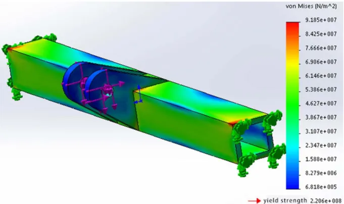
Figure 7. Finite element analysis for critical part.
The simulation results show that the maximum stress of the material is less than the yield limit of the material. In the whole process of supporting the function of the back, the corresponding bearing beam will not have large deformation, which proves the feasibility and rationality of the scheme. For the finite element analysis at other load beam and hinges, similar to the above-described load beam, it will not be repeated.
7. Conclusion
The back support mechanism described in this article is simple in structure, and the core component for realizing the back support is an electric push rod, which is a standard part and has strong interchangeability. By solving the best fixed position of the electric push rod, the load required by the electric push rod, the load beam, and the hinge is greatly reduced, the possibility of material damage is reduced, and the safety of the back support mechanism is improved. And in the process of back support, the angular velocity changes slowly, and the back bed plate assembly is stable. The mechanism meets the requirements of mechanical development, saves materials and has a good application prospect.
References
[1] Zhongqiu Li. The study of diversified pension model under the background of population aging in China [D]. Southwestern University of Finance and Economics, 2013.
[2] Diansheng Chen, Jinghua Liu, Lanlan Yin, The new model and necessity of serving robots to assist elderly living robot technique and application, 2010(02):2-4.
[3] Feng Li. Design and simulation of a new kind of multifunctional wheelchair [D]. Tianjin University of Technology, 2013.
[4] Yuxing Dai. Design and study on a new multifunctional nursing wheelchair bed [D]. Tianjin University of Science and Technology, 2014.
[5] Jianguo Zhang, Bohai Zhang, Qiang Xue. Humanoid design and dynamic emulation of new multifunctional bed [J]. Machinery Design & Manufacture, 2009(09):19-20.
[6] Cheng Chen. Research and development of automobile seat regulator utilized planetary gear [J]. Automotive Practical Technology, 2012(08):9-12.
[7] Yazhen He, Jinyuan Tang, Haifeng Chen. A bond graph modeling method of swing guide-bar mechanismbased on the bond graph method [J]. Journal of Mechanical Transmission, 2011, 35(10):47-50.
[8] Zhen Li, Lixin Zhan, Jinhai Zhang, Jizhu Liu. The application of human engineering in medical equipment design [J]. China Medical Devices Information, 2012, 18(08):1-5+40.
[9] Ying Xu, Xuyu Zhu, Honggang Yang, Lin Guo. Ergonomics design of automobile seats for drivers [J]. Development & Innovation of Machinery & Electrical Products, 2008(01):28-30. [10] Liang Cai, Jingfeng Shen, Xinping Deng. Placement