Received 10 October 2019; received in revised form 12 December 2019; accepted 2 February 2020.
To cite this article: Abu Bakar et al. (2020). Influence of rounded cutting-edge radius and machining parameters on surface roughness and tool wear in milling AISI H13 steel under dry and cryogenic machining. Jurnal Tribologi 24,
Influence of rounded cutting-edge radius and machining
parameters on surface roughness and tool wear in milling AISI H13
steel under dry and cryogenic machining
Husni Nazra Abu Bakar, Jaharah A. Ghani *, Che Hassan Che Haron
Faculty of Engineering & Built Environment, Universiti Kebangsaan Malaysia, 43600, Bangi, Selangor, MALAYSIA.
*Corresponding author: jaharahaghani@ukm.edu.my
KEYWORDS ABSTRACT
Cutting-edge radius End milling
Surface Roughness Tool wear
Uncoated Carbide Tool
1.0 INTRODUCTION
AISI H13 hardened steel is a material which is difficult to machine, is characterized as having excellent mechanical properties due to high thermal softening, hardenability, strength and toughness and classified as chromium hot work tool steels according to its principal alloying elements (Roberts et al., 1998). The hot work tool steels are usually alloyed to low or medium carbon content between 0.35-0.45wt% to provide high toughness while additions of carbide forming elements for instance chromium, tungsten, molybdenum and vanadium is to provide high temper resistance and hot hardness. The chromium hot work tool steels are relatively low alloyed with about 3-5 wt.% of Chromium (Cr) content as well as ≤ 1 wt.% of Vanadium (V) and ≤ 3 wt.%
of Molybdenum (Mo). The relatively low alloy content offers toughness and hardness around 40-55 HRC in the heat-treated condition. High hardenability of the tool steel grade is obtaining during the quenching process through a secure alteration in order to get the desired martensite microstructure. Lowering carbon concentration in martensite and limiting the size of alloy carbide particles can provide toughness to the tool steel while fine dispersed chromium and vanadium carbides precipitate when tempering at high temperature which provides good high temperature strength (Roberts et al., 1998). Thus, it is widely used in manufacturing, with applications in hot work (44-48 HRC), forging and extrusion dies (46-49 HRC), blanking tools and bending tools (50-52 HRC), swaging dies (53-55 HRC), die casting (52-54 HRC), injection molds and other applications on the macro and microscale size (Afazov et al., 2012; Ghang and Guo, 2009). While machining hardened steel, the cutting tool is repeatedly exposed to extremely high mechanical and thermal stresses, which can cause chipping and wear on the edge of the cutting tool. High mechanical energy during the cutting process is due to the plastic deformation formed at the primary shear zone and at the tool-chip interface which is converted into heat. Seventy percent (70%) of the heat is absorbed by the generated chip while twenty percent (20%) and another ten percent (10%) of the heat is transferred to the workpiece and cutting tool, respectively (Tamerabet et al., 2018). Though, the small amount of heat conducted into the tool (10% of the total heat rate), but it is sufficient enough to create high temperatures near the cutting edges, which can even reach the temperature value of 1100°C (Trent and Wright, 2000). Ravi and Kumar, 2011, states that the contact friction between the tool-workpiece and tool-chip interfaces will create high temperatures on the cutting tool. Furthermore, the heat created increases workpiece surface roughness and decreases the tool life and the dimensional accuracy of the work material (Ravi and Kumar, 2011; Carvalho et al., 2006). Therefore, cemented carbide cutting tool which contain a WC, C and Co mixture that can withstand the temperature up to 2750 °C is extensively used in machining hard materials at higher speeds compared to high speed steel (HSS) cutting tool which limited to operation only below 550°C (Trent and Wright, 2000; Boothroyd and Knight, 1998). Thus, to reduce heat and friction between tool-workpiece and tool-chip interfaces, and also to sweep away the chips from the tool, cutting fluid is applied, which acts as a coolant. Moreover, the suitable design of cutting edge radius, machining parameters and types of cutting fluid used, must be properly selected as it can significantly affect the performance of a tool and stability of machining process in terms of material deformation and flow, tool wear and cutting forces as well as heat distribution, tool-chip friction, roughness of machined surface and residual stresses (Denkena et al., 2013; Ravi and Kumar, 2011; Wyen and Wegner, 2010).
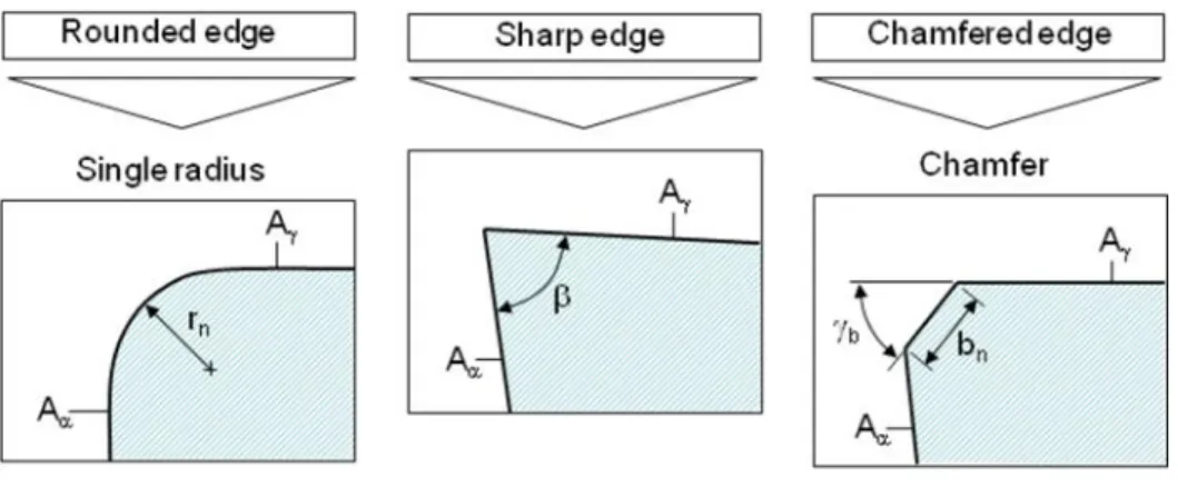
of the machined workpiece, also referred to as surface integrity (Zhao et al., 2017; Wang et al., 2013). Hence, three fundamental cutting-edge shapes which are rounded, sharp and chamfered are defined as shown in Figure 1. Edges are classified as rounded if cutting-edge radius, rn is
between range 5 and 50 μm, whereas edges are classified as sharp if the cutting-edge radius rn is
less than 5 μm. A chamfered edge is formed through the joining of the tool face Aγ, chamfer length
bn and flank face Aα. The characteristics of the chamfered edge is dependent both on chamfer
length and chamfer angle used (Rech, 2005).
Figure 1: Variations of cutting-edge shape.
Furthermore, in machining, the application of coolants such as liquid nitrogen (LN2) into the
tool-chip interfaces should provide effective cooling and lubrication without polluting the environment and is classified as cryogenic treatment. Liquefied nitrogen boils on contact with the workpiece (boiling point = -196℃) to form nitrogen gas and becomes part of the air. Therefore, it is considered naturally recycling and environmentally friendly (Balaji et al., 2015; Ravi and Kumar, 2011). Balaji et al., 2015 also state other benefits provided by cryogenic machining where the method of cryogenic cooling gives the biggest impact in increasing tool life and improvement of surface finish as well as reducing the cutting forces. On the other hand, dry machining is performed without using any coolant. The problem with dry machining is that it relies on the less effective method of cooling by air, making it unproductive for the removal of heat during machining (Ravi and Kumar, 2011). But then, some research state that, in cases of interrupted cutting, dry cutting improves tool life due to an avoidance of thermal shock to the tool (Sreejith and Ngoi, 2000). In some cases, the required cutting forces using dry cutting is lower than what occurs under wet cutting due to the effect of increased cutting temperature and a thermal softening of the materials (Thomas et al., 2016). Moreover, when concerns on cost reduction and the best way to sustainability, dry machining is preferred which more economical than machining with cutting fluid due to the absence of lubricants and coolants, which results in a reduced use of resources and no further danger to health of operators due to prohibitive contact with toxic cutting fluid substances (Devillez et al., 2011; Balaji et al., 2015; Thomas et al., 2016).
increase as the radius of edge hone increase. Additionally, the nano-hardness, depth of plastic deformation and compressive residual stress of machined surface increase with the increase of radius of edge hone. Experimental investigation on face milling of AISI H13 steel (46-47 HRC) for obtaining thorough understanding of the effect of cutting speed on cutting forces and surface roughness was performed by Cui et al., 2015. It was found that a relatively low cutting force obtained at the cutting speed of 1400 m/min and low surface roughness (below 0.1 µm) achieved when the value of cutting speed reached below than 1400 m/min. The effect of machining parameters on cutting temperature, and a comparison of surface roughness in dry and cryogenic conditions for the milling of AISI 4340 alloy steel was studied by Muhamad et al., 2019. The results show that the most important machining process parameter for the temperature generated during machining was cutting speed. Also, surface roughness increases as feed rate increased and the application of LN2 in cryogenic machining had effectively reduced the average surface
roughness with a significant of 14-24% in cryogenic machining compared to dry machining. The influence between clearance angle, rake angle and cutting-edge radius with the aim of improving the current cutting tool life in milling Inconel 718 were investigated by Celaya et. al.,2019. The parameters were analyzed by Finite Element Method (FEM) and observed that cutting edge radius was the most significant factor and had the highest influence on tool wear followed by clearance angle and rake angle. Based on the results , a series of experimental tests were conducted with different cutting edge radius values which were 3, 15 and 20 µm and found that cutting edge radius of 20 µm implies a significant improvement in cutting tools quality due to the tool life increase achieved by 25% in comparison with the current cutting tool with 3 µm of cutting edge radius. Furthermore, the influence of machining parameters, jet temperature and cooling conditions on cutting force and surface integrity was analysed by Gong et al., 2019 through the cryogenic milling experiments on 35CrMnSiA high strength steel. The results indicated that the jet temperature, cooling conditions and cutting speed had a remarkable influence on the cutting force and surface integrity of the steel. A reduction in jet temperature with the same cutting speed used resulted in an increase of cutting force and decrease the surface roughness value along with microhardness of machined surface. Ghani et al., 2004 have studied the performance of P10 TiN coated carbide tools for end milling of AISI H13 steel at higher cutting speeds and found that the feed rate and depth of cut had the most significant effects on tool life. Elbestawi et al., 1997 investigated the cutting tool performance and surface finish of AISI H13 tool steel for different process parameters and observed that the average cutting force for a 45 HRC tool was larger than that for a 55 HRC tool. It was also observed that flank wear was the main mode of failure for CBN tools. Zhou et al., 2017 evaluated the effects of cutting edge radius on surface roughness and tool wear in hard turning of AISI 52100 steel, and claimed that edge radius of 30 µm gives better machining performance in terms of surface roughness and tool wear compared to other values of edge radius studied. Ravi and Kumar, 2011 organized an investigation into cryogenic cooling by use of LN2 in the end milling of hardened AISI D3 tool steel using TiN-coated carbide inserts. The
outcome demonstrated that machining with LN2 lowers cutting temperature, tool flank wear,
cutting forces and surface roughness as compared with wet and dry machining. Haron et al., 2019 studied wear mechanisms of coated tungsten carbide when machining Inconel-718 under cryogenic and dry conditions. The results showed that lower cutting speeds give longer tool life under cryogenic machining which reduces the rate of tool wear progression of nose wear compared to dry cutting.
researches focusing on the influence of cooling strategies on the surface roughness and tool life of cutting tool, hardly any research presents the effect of cutting edge radius and cooling strategies on the surface roughness and tool life of uncoated cutting tool on AISI H13 steel. Therefore, the aim of this paper is to explore the influence of cutting-edge radius and machining parameters towards machining performance related to surface roughness, tool flank wear and tool life through the process of end milling AISI H13 steel using uncoated cemented carbide cutting tools under dry and cryogenic machining.
2.0 EXPERIMENTAL PROCEDURE
2.1 Workpiece Material
The workpiece material used in the study was AISI H13 steel. The workpiece was in the shape of a rectangular block with dimensions of 125 mm x 100 mm x 50 mm and was hardened to 52±1 HRC. The chemical composition and mechanical properties of AISI H13 steel are listed in Table 1 and 2 respectively.
Table 1: Chemical composition for AISI H13 in percentage by weight adopted from ASSAB Steel (Malaysia) Sdn Bhd.
Elements C Cr Mn Mo Si V
Weights (%) 0.39 5.3 0.4 1.3 1.0 0.9
Table 2: Thermo-mechanical properties of AISI H13 steel at room temperature adopted from Li et al., 2018.
Density (kg/m3)
Young’s
modulus (GPa)
Poisson
’s ratio Hardness (HRC) Yield strength (MPa)
Area reduc tion
Thermal conducti vity
Specific heat (J/kg.k)
7800 211 0.28 52±1 1425 23.0 23.01 417
2.2 Cutting Tools
Uncoated four flute end mill type of cutting tool using cemented carbide K Grade as tool material with 6 mm diameter and cutting-edge radius of 0.03 and 0.05 mm were used in the study. Uncoated cemented carbide cutting tool was selected in the study in order to have a good understanding of the relationship between tool wear performance and surface integrity that can be used as the basis of future developments of tooling and workpiece respectively.
The tool geometry for rake and helix angle were 10ᵒ and 40ᵒ respectively. The tool material
The experiment was performed on vertical machining centers of Spinner VC450. The detailed experimental conditions were as listed in Table 3.
Table 3: Experimental conditions.
Machine tool Spinner VC450 (vertical machining center)
Cutting tool Solid end mill
Diameter 6 mm
Rake angle, α 10ᵒ
Helix angle 40ᵒ
Milling operation Down milling
Workpiece material Hardened AISI H13 (52±1 HRC)
Cutting speed, V(m/min) 200 (spindle speed n = 10610 r/min) Feed rate, f (mm/tooth) 0.03, 0.06 (1273 , 2546 mm/min) Axial depth of cut, ap (mm) 0.1, 0.2
Radial width of cut ae (mm) 6.0 Cutting edge radius, rn (mm) 0.03, 0.05
Cooling method Dry and cryogenic cooling (LN2)
2.3 Experimental Setup and Procedure
Taguchi’s design experiment with a standard L8(27) orthogonal array was utilized in the
experiment. This form of orthogonal array was chosen because it has the ability in checking iterations between factors where each row of the matrix indicates one trial but in randomized orders. The two levels of each factors were represented in the matrix via numbers of '0' and '1' or '1' and '2' (Park, 1996). Factors and levels used was tabulated in Table 4 and the machining parameter combination adopted in Taguchi method L8(27) orthogonal array was presented in
Table 5. All experiments were done under dry machining conditions. Additional cryogenic machining was only applied for experiment number 1 and experiment number 8 responded to the highest and lowest results of tool life from dry machining to get good understanding of the outcomes involving the quality of surface roughness, progression of tool wear and tool life between both machining conditions. The machining parameters applied were 0.03 and 0.06mm/tooth of feed rate and axial depth of cut of 0.1 and 0.2 mm. Cutting speed and radial width of cut were kept constant at 200 m/min and 6.0 mm respectively. Dry machining was performed without using any coolant while cryogenic machining was performed using liquid nitrogen. The liquefied nitrogen was shot directly onto the chip-tool interface through a 7.5 mm nozzle with a flowrate of 0.807 kg/s.
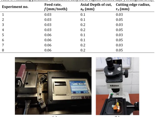
In this experiment, the surface roughness (Ra) of the workpiece was measured using a portable
surface roughness tester, Mitutoyo SJ-310, at random locations along the length of the cut with a sampling length of 0.8 mm. The tool wear of the cutting tool was measured after the first path using a Mitutoyo TM-500 as shown in Figure 2. The requirement for wear measurement depended on the rate of the wear progress and according to the tool wear criteria as per ISO 8688-2:1989(E), where there was a recommendation for the machining to be stopped when the average of flank wear, VBmax reached 0.3 mm and maximum flank wear reached 0.5 mm when using the cutting
et al., 2016). All measurements were repeated three times and the final value of surface roughness and tool wear for all machining experiments were taken from the average of the repeated measurements.
Table 4: Levels and factors applied in experiment (cutting speed and radial width of cut is kept constant at 200 m/min and 6 mm, respectively).
Factors Level
1 2
A - feed-rate, f (mm/tooth) 0.03 0.06
B - axial depth of cut, ap (mm) 0.1 0.2
C - cutting-edge radius, rn (mm) 0.03 0.05
Table 5: Machining parameter combination adopted in Taguchi method L8(27) orthogonal array.
Experiment no. Feed rate, f (mm/tooth) Axial Depth of cut, ap (mm) Cutting edge radius, rn (mm)
1 0.03 0.1 0.03
2 0.03 0.1 0.05
3 0.03 0.2 0.03
4 0.03 0.2 0.05
5 0.06 0.1 0.03
6 0.06 0.1 0.05
7 0.06 0.2 0.03
8 0.06 0.2 0.05
(a)
(b)
3.0 RESULTS AND DISCUSSION
3.1 Surface Roughness
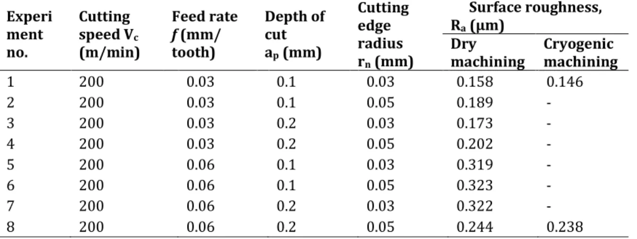
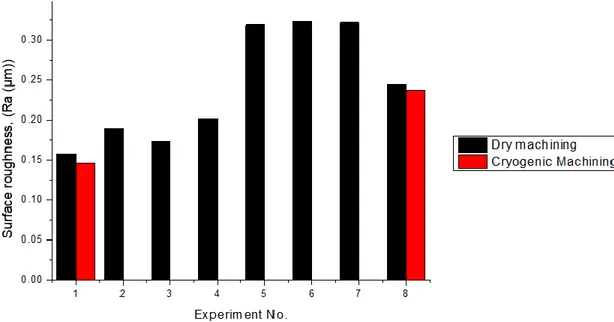
The influence of rounded cutting-edge radius and machining parameters on the surface roughness (Ra) of the workpiece in dry and cryogenic machining using LN2 coolant,
correspondingly can be seen in Table 6 and Figure 3. It can be observed that smaller cutting-edge radius of 0.03 mm with low feed rate and depth of cut of 0.03 mm/tooth and 0.1 mm respectively, gives better performance in the average of surface roughness value in both machining conditions. The results also show that, surface roughness is reduced with the application of cryogenic machining, resulting in improved surface quality of the workpiece. The lowest surface roughness of the workpiece was 0.158 and 0.146 µm for both dry and cryogenic machining, as shown in experiment number 1, with rounded cutting-edge radius of 0.03 mm, feed rate and depth of cut of 0.03 mm/tooth and 0.1 mm respectively. The major reason for this could be the stability of the cutting process applied (Zhao et al., 2017). The percentage reduction of the average surface roughness due to cryogenic machining was found to be 7.59 % over that of dry machining. Furthermore, for all machining experiments, cryogenic machining reduced the average surface roughness by 2.46-7.59 % compared to dry machining. The lowest result of surface roughness obtained for 0.03 mm in cutting-edge radius is in parallel with results published by Zhao et al., 2017. The improved surface finish resulted in cryogenic machining is due to lower cutting temperature generated during the machining process, hence lowering the cutting forces and tool wear (Ravi and Kumar, 2011; Zhang et al., 2012). Similar findings were reported by Dhananchezian et al., 2011 who also obtained a reduction in cutting force in turning AISI 304 stainless steel with cryogenic application made on the rake and flank surfaces of the PVD TiAlN coated tungsten carbide. Effective reduction of cutting temperature had been achieved when the liquid nitrogen jet was pointed to the cutting edge, maintaining the sharpness and hardness of the tool hence lessen the abrasion, adhesion and diffusion wear (Ravi and Kumar, 2011; Singh et al., 2016). Cryogenic condition also improves the chip breakability during machining and diminishes the tendency of adhesion of chips to the tool resulting in less scratch on the surface finish (Jerold and Kumar, 2011).
Table 6: Result for surface roughness in dry and cryogenic machining. Experi
ment no.
Cutting speed Vc (m/min)
Feed rate f (mm/ tooth)
Depth of cut ap (mm)
Cutting edge radius rn (mm)
Surface roughness, Ra (µm)
Dry
machining Cryogenic machining
1 200 0.03 0.1 0.03 0.158 0.146
2 200 0.03 0.1 0.05 0.189 -
3 200 0.03 0.2 0.03 0.173 -
4 200 0.03 0.2 0.05 0.202 -
5 200 0.06 0.1 0.03 0.319 -
6 200 0.06 0.1 0.05 0.323 -
7 200 0.06 0.2 0.03 0.322 -
Figure 3: Surface roughness for all machining test.
3.2 Tool Wear
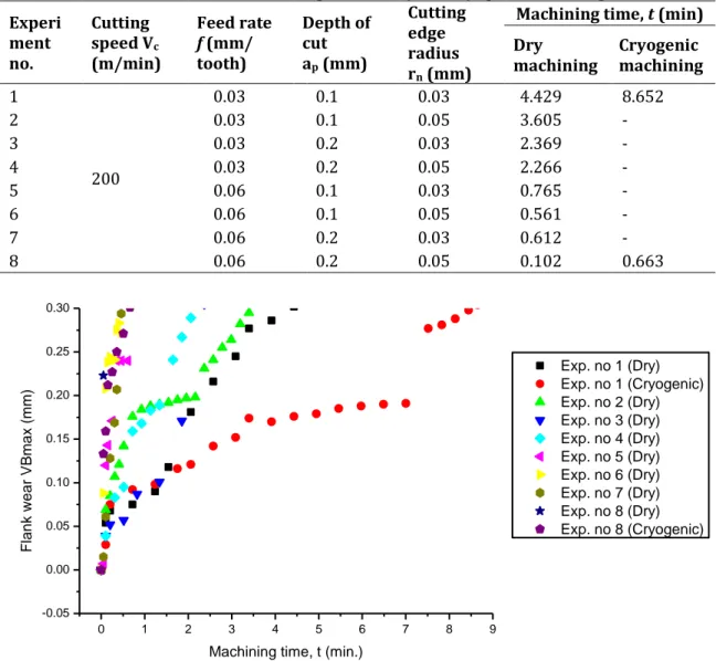
The effect of rounded cutting-edge radius and machining parameters on machining time, t
for dry and cryogenic machining was tabulated as in Table 7. In addition, Figure 4 shows how the tool flank wear changed with respect to machining time. For all machining experiments, the machining operation was stopped when the flank wear, VBmax value reached about 0.3 mm. It
performance in terms of tool flank wear rate and consequently tool life, which is similar to the results obtained by Zhao et al., (2017).
Table 7: Results of machining time for dry and cryogenic machining. Experi ment no. Cutting speed Vc (m/min) Feed rate f (mm/ tooth) Depth of cut ap (mm) Cutting edge radius rn (mm)
Machining time, t (min) Dry
machining Cryogenic machining 1
200
0.03 0.1 0.03 4.429 8.652
2 0.03 0.1 0.05 3.605 -
3 0.03 0.2 0.03 2.369 -
4 0.03 0.2 0.05 2.266 -
5 0.06 0.1 0.03 0.765 -
6 0.06 0.1 0.05 0.561 -
7 0.06 0.2 0.03 0.612 -
8 0.06 0.2 0.05 0.102 0.663
Figure 4: Relationship of flank wear VBmax with machining time.
0 1 2 3 4 5 6 7 8 9
-0.05 0.00 0.05 0.10 0.15 0.20 0.25 0.30 F la n k w e a r VBma x (mm)
Machining time, t (min.)
4.0 CONCLUSION
The experiments were conducted on end milling of hardened AISI H13 steel using dry and cryogenic machining to investigate the influence of rounded cutting edge radius and machining parameters towards cutting performance which included surface roughness of workpiece and tool flank wear as well as tool life of the cutting tool. Based on the results of the experimental investigation, conclusions can be made that a smaller cutting edge radius with low feed rate and depth of cut gives better performance in the average of surface roughness value and better performance of tool flank wear rate in both dry and cryogenic machining. For all machining experiments, cryogenic machining reduced the average surface roughness by 2.46-7.59 % and increased the tool life of cutting tool by 48.81-84.62 % compared to dry machining. This was due to the better cooling and lubrication effect through substantial reduction in the cutting temperature resulting from the use of LN2 coolant. Furthermore, rounded cutting-edge radius of
0.03 mm demonstrated better performance of surface roughness, tool flank wear rate and consequently resulted in improved tool life of cutting tool under both machining conditions, compared to 0.05 mm edge radius.
ACKNOWLEDGEMENT
The author would like to express gratitude to the Malaysian Government and Universiti Kebangsaan Malaysia for financial provision under grant numbers GUP-2017-048 and FRGS/1/2019/TK03/UKM/01/2; as well HPMT Industries Sdn. Bhd for cutting tools supply.
REFERENCES
Afazov, S. M., Ratchev, S. M., & Segal, J. (2012). Prediction and experimental validation of micro-milling cutting forces of AISI H13 steel at hardness between 35 and 60 HRC. The International Journal Advance Manufacturing Technology, 62(9-12), 887-899.
Balaji, V., Ravi, S., Chandran, P. N., & Damodaran, K. M. (2015). Review of the cryogenic machining in turning and milling process. International Journal of Research in Engineering and Technology, 4(10), 38-42.
Boothroyd, G. & Knight W. A. (1998). Fundamentals of Machining and Machine Tool, 3rd edn, New York: Taylor and Francis.
Carvalho, S. R., Lima e Silva, S. M. M., Machado, A. R. & Guimar~aes, G. (2006). Temperature determination at the chip tool interface using an inverse thermal model considering the tool and tool holder. Journal of Materials Processing Technology, 179, 97-104.
Celaya, A., Pereira, O., Gonzalez, H., Gomez-Escudero, G., Lucio, P., Fernandez-Valdivielso, A. & Lopez de Lacalle, L. N. (2019). Influence of cutting edge radius on tool life in milling Inconel 718. AIP Conference Proceedings 2113, 080019, 1-6.
Cui, X., Guo, J., & Wang, X. (2015). Cutting force in high speed face milling AISI H13 steel. Key Engineering Materials, 667, 35-40.
Dhar, N., Paul, S., & Chattopadhyay, A. (2002). Machining of AISI 4140 steel under cryogenic cooling—Tool wear, surface roughness and dimensional deviation. J. Mater. Process. Technol., 123, 483–489.
Denkena, B., Kohler, J., & Ventura, C. E. H. (2013). Customized cutting edge preparation by means of grinding. Precision Engineering, 37(3), 590-598.
Elbestawi, M. A., Chen, L., Becze, C. E. & El-Wardany, T. I. (1997). High speed milling of dies and moulds in their hardened state. CIRP Annals, 46(1), 57-62.
García, J., Ciprés, V. C., Blomqvist, A., & Kaplan, B. (2019). Cemented carbide microstructures: a review. International Journal of Refractory Metals & Hard Materials, 80, 40–68.
Ghang, S., & Guo, Y. B. (2009). An experimental and analytical analysis on chip morphology, phase transformation, oxidation, and their relationships in finish hard milling. International Journal of Machine Tools and Manufacture, 49(11), 805-813.
Ghani, J. A., Choudhury, I. A., & Masjuki, H. H. (2004). Performance of P10 TiN coated carbide tools when end milling AISI H13 steel at high cutting speed. Journal of Material Processing Technology, 153-154, 1062-1066.
Gong, L., Zhao, W., Ren, F., He, N., Li. L., Xu, Q., & Khan, A. M. (2019). Experimental study on surface integrity in cryogenic milling of 35CrMnSiA high-strength steel. The International Journal of Advanced Manufacturing Technology, 103(1-4), 605-615.
Haron, C. H. C., Ghani, J. A., Azhar, M. F., & Halim, N. H. A. (2019). Wear mechanisms of coated tungsten carbide when machining Inconel 718 under cryogenic and dry conditions. Jurnal Tribologi, 22, 108-116.
Jaharah, A. G., Che Hassan, C. H.,Ghazali, M. J., Sulong, A. B., Omar, M.Z., Nuawi M. Z., & Ismail, A.R. (2009). Performance of uncoated carbide cutting tool when machining cast iron in dry cutting condition. International Journal of Modern Physics B, 23(6), 1796-1801.
Jerold, B.D., & Kumar, M.P. (2011). Experimental investigation of turning AISI 1045 steel using cryogenic carbon dioxide as the cutting fluid. Journal of Manufacturing Processes, 13(2), 113-119.
Kaynak, Y. & Gharibi, A. (2018). Progressive tool wear in cryogenic machining: the effect of liquid nitrogen and carbon dioxide. J. Manuf. Mater. Process., 2(31), 1-12.
Kaynak, Y., Karaca, H. E., Noebe, R. D., & Jawahir, I. S. (2013). Tool-wear analysis in cryogenic machining of NiTi shape memory alloys: A comparison of tool-wear performance with dry and MQL machining, Wear, 306, 51–63.
Li, B., Zhang, S., Yan, Z., & Jiang, D. (2018). Influence of edge hone radius on cutting forces, surface integrity, and surface oxidation in hard milling of AISI H13 steel. International Journal of Advance Manufacturing Technology, 95, 1153-1164.
Muhamad, S. S., Ghani, J. A., Juri, A., & Haron, C. H. C. (2019). Dry and cryogenic milling of AISI 4340 alloy steel. Jurnal Tribologi, 21, 1-12.
Park, S. H. (1996). Robust Design and Analysis for Quality Engineering, London UK: Chapman & Hall.
Ravi, S., & Kumar, M.P. (2011). Experimental investigation on cryogenic cooling by liquid nitrogen in the end milling of hardened steel. Cryogenics, 51, 509-515.
Rech, J. (2005). Influence of cutting edge preparation and surface issues. International Conference Smart Solutions for Metal Cutting, HSS Forum Aachen, 1-12.
Singh, T., Singh, G., & Singh, A. (2016). Effect of cryogenic treatment of cutting tool on surface roughness in machining of stainless steel (304 H). IJSRSET, 2(6), 254-262.
Sreejith, P. & Ngoi, B. (2000). Dry machining: machining of the future. Journal of materials processing technology, 101(1), 287-291.
Tamerabet, Y., Brioua, M., Tamerabet, M. & Khoualsi, S. (2018). Experimental Investigation on Tool Wear Behavior and Cutting Temperature during Dry Machining of Carbon Steel SAE 1030 Using KC810 and KC910 Coated Inserts. Tribology in Industry, 40 (1), 52-65.
Thomas, J., Kunte, K., & Arote, V. (2016). Review on machining techniques: dry machining and cryogenic machining. International Journal of Advance Research in Science and Engineering (IJARSE), 5(2), 188-194.
Tran, S. (2018). Microstructure investigations of WC-Co cemented carbide containing ɳ-phase and Cr, Uppsala universitet, 1-57.
Trent, E. M., & Wright, P.K. (2000). Metal Cutting, 4th ed., Butterworth–Heinemann, Boston, USA, 446.
Wang, X., Huang, C., Zou, B., Liu, H., & Wang, J. (2013) Effects of geometric structure of twist drill bits and cutting condition on tool life in drilling 42CrMo ultrahigh-strength steel. Int J Adv Manuf Technol, 64, 41-47.
Wyen, C. F., Jaeger, D. & Wegener, K. (2013). Influence of cutting edge radius on surface integrity and burr formation in milling titanium. Int J Adv Manuf Technol, 67, 589–599.
Wyen, C.F., & Wegner, K. (2010). Influence of cutting edge radius on cutting forces in machining titanium. CIRP Annals-Manufacturing Technology, 59(1), 93-96.
Zhang, C., Zhang, S., Yan X., & Zhang, Q. (2016). Effect of internal cooling channel structures on cutting forces and tool life in side milling of H13 steel under cryogenic minimum quantity lubrication condition. International Journal of Advance Manufacturing Technology, 83(5-8), 975-984.
Zhang, S., Li, J.F., & Wang, Y.W. (2012). Tool life and cutting forces in end milling Inconel 718 under dry and minimum quantity cooling lubrication cutting conditions. Journal of Cleaner Production, 32, 81-87.