AbstractThrough the experimental work on dry end milling of an aeronautical material Ti-6242S, the extended Taylor models for volume of material removal (Q.Vc
2.2-.fz1.98.aa1.96=3.318x10³) and tool life (T.Vc3.3.fz2.97.aa
2.80-=1.531x10⁶) are resulted for characterizing the perfor-mance of the off-centre ball end milling alloyed carbide tool (W-(Ti/Ta/Nb)C-Co). Further analysis on the models result the optimum cutting conditions (Vc 88 m/min at fz
0.20 mm/tooth, Vc 113.5 m/min at fz 0.15 mm/tooth, and Vc
163 m/min at fz 0.10 mm/tooth) as the best compromise
among cutting speed (Vc), material removal rate
(MRR=Q/T) (cm3 /min) and T (min). Moreover, it can be interpreted that the tool failure mode, tool wear mecha-nism and the behaviour of tool performance are changing at the optimum cutting conditions given by the models that plot in a chart of MRR-T-Vc. By utilizing the FEM
simu-lation, the chip morphology, contact length at the tool-chip interface and the tribological aspects (temperature, pres-sure) in machining at the optimum cutting conditions can be evaluated. The results of simulation support the inter-pretation of experimental results.
Keywords Extended Taylor model, Chip morphology, material removal rate, Optimum cutting condition, Tribo-logical aspects.
I. PENDAHULUAN
he problem addressed by the study reported in this paper is the issue on dry machining. Dry machining has two main impacts on metal cutting industry, i.e. eco-logy and economy. For the ecoeco-logy aspect, as far as cut-ting fluids are concerned, changes in ecological legisla-tion –mainly in European countries– imposed increasing pressure upon the metal cutting industry. For the econo-my, cutting fluids represent 16-20% of the production cost [1].
There are two main purposes of cutting fluids used in metal cutting process, i.e. as a lubricant and as a coolant. The absence of cutting fluids in metal cutting means higher friction and higher cutting temperature during cut-ting. They become serious problems for machinability (tool life and surface finish) because at the same time; the machining parameters should keep equal to the con-dition of machining under wet cutting (even for high speed machining). Since cutting fluid is absent in dry machining, the only one opportunity to ensure dry
Manuscript received July 6, 2007; revised May 21, 2008
1 Armansyah G. is with department of Mechanical Engineering,
Faculty of Engineering , University of Sumatera Utara, INDONESIA
machining can successfully be done in metal cutting is to provide a suitable cutting tool.
The objective of the present study, in general, is seek-ing the suitable cuttseek-ing tool for dry machinseek-ing of aero-space material (titanium based alloy) and particularly in this paper; performance of the alloyed carbide tool is studied. The expected goals from this study are the tool life model and the optimum cutting condition of the allo-yed carbide tool when used in end milling of titanium al-loy Ti-6242S under dry cutting environment.
II. MATERIALS AND METHODS A. Materials
The forging stock of the (α+β) titanium alloy Ti-6242S is the workpiece material in this study. The che-mical composition and physical properties of this ma-terial are given in Tables 1 and 2, respectively. In order to minimize the effect of previous processes in material production, prior to the end milling trials, the workpiece materials were trued and cleaned by face milling their outer surfaces.
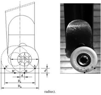
The cutting experiments were carried out using the alloyed carbide tool insert (grade P of ISO codes) with insert diameter (Di) of 12 mm (see Table 3). In end milling trials, each insert was rigidly mounted on a tool holder to provide the off centre ball end mill configu-ration with nominal diameter (Dn) of 16 mm and the tool geometry of cutting rake (γo) –6o, axial rake (γp) –6o, and radial rake (γf) –2o (Figure 1). The ball end mill tool configuration and end milling process are selected since they are widely used in machining the complex profiles (contouring) of aerospace components such as turbine blade in which Ti-6242S is used to replace the Ti-64 [2].
B. Methods
Machining trials were carried out on a 3-axis CNC vertical milling machine with 9 kW motor. This machine has a variable spindle speed range from 60 to 10,000 rpm.
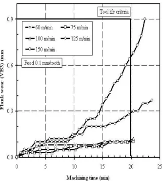
The tool rejection criteria stipulated for the end mil-ling trials were based on the ISO 8688-2 [3] where uni-form flank wear (VB1) ≥ 0.2 mm, non-uniform flank we-ar (VB2) ≥ 0.8 mm, localized flank wear (VB3) ≥ 0.9 mm, machining time maximum ≥20 minutes and mini-mum ≥3 minutes. The cutting conditions for testing are arranged as follows:
Armansyah Ginting
1Study on Carbide Tool Performance in
Green Machining of
Aeronautical Material: Q-T Models and Finite
Element Analysis
Fig. 1. The off centre ball end mill. (aa=axial depth-of-cut; De=effective
diameter; Dn=nominal diameter; Di=insert diameter; d=off centre
radius).
TABLE 1
CHEMICAL COMPOSITION OF TI-6242S
Elements Min.(%) Max.(%)
Al 5.50 6.50
Zr 3.60 4.40
Mo 1.80 2.20
Sn 1.80 2.20
Fe - 0.25
O2 - 0.15
Si - 0.10
C - 0.05
N2 - 0.05
H2 - 0.015
Y - 0.005
Others 0.100 0.300
Ti to 100%
TABLE 2
PHYSICAL PROPERTIES OF TI-6242S
Tensile strength (MPa) ≥ 895
Yield strength (MPa) 830
Creep stress (MPa) 240
Hardness (HRc) ~36
Density (kg/m3) 4540
Linear thermal expansion (10-6/oC) 9.9
Thermal conductivity (W/mK) 8 – 12
TABLE 3
THE PROPERTY OF CUTTING TOOL
Composition
69.8%WC 9.50%Co 20.7% (Ti/Ta/Nb)
Grain size (µm) 1 - 2
Hardness 25 oC (HV10) 1485
Hot hardness 800 oC (kg/mm2) 600
Density (g/cm3) 11.4
Thermal conductivity (W/mK) 45
Thermal expansion (10-6/K) 6.1
Modulus of elasticity (GPa) 510
Traverse rupture (GPa) 2.2
1. Sensitivity stage. In this stage, the cutting condition is based on the suggestion of the tool manufacturer. Cutting condition was started from 60 m/min and the
cutting speed was step by step increased up to tool life about 5 minutes. The 5 minutes tool life is consi-dered as the minimum limit to determine the highest cutting speed in cutting tool testing [3]. The output of this stage is the cutting condition with tool life criteria of (5 minutes<tool life<20 minutes).
2. Performance stage. The cutting condition resulted from the previous stage was intensively tested in this stage. In the meaning of obtaining the reliable results and resulting the extended Taylor tool life model (T), the factorial design 23 with 4 centre points and 3 replications (total 36 data) was utilized. Besides tool life model, the model for volume of material removal (Q) was also the output of this stage.
The extended Taylor tool life model resulted from the performance stage was used to simulate the various cutting conditions. From the simulation, tool life (T) and Material Removal Rate (MRR) that obtained from (Q/T) were plotted to determine the optimum cutting condition of the alloyed carbide tool. Finally, in order to support the results of experimental works, the machining simula-tion by Thirdwave Advantedge software was carried out.
III. RESULT AND DISCUSSION A. Sensitivity stage
The cutting conditions used in this stage was started from cutting speed (Vc) of 60 m/min, tooth feed (fz) of 0.1 mm/tooth, axial depth of cut (aa) of 2 mm and radial depth of cut (ar) of 8.8 mm (or 55% of tool nominal diameter) (aa and ar were kept constant for the experi-mental work). This combination is a typical cutting con-dition used for roughing operation in the manufacturing industry and as the suggestion of tool’s manufacturer.
The results of end milling testing at this stage are pre-sented in Figures 2 and 3. It can be seen that at constant axial and radial depth of cuts, cutting condition for the alloyed carbide tool can be increased up to cutting speed of 150 m/min and tooth feed of 0.15 mm/tooth (higher cutting speed of 175 m/min, tool life is less than 5 minutes and may end with catastrophic failure). At all cutting conditions (from 60 to 150 m/min), it was observed that localized flank wear (VB3) could be the main criterion to determine tool life.
Based on tool life and flank wear progression data plotted in Figures 2 and 3 and supported by the analysis of surface topography of the machined surface (the detail analysis of surface topography is not reported in this paper); the cutting conditions recommended for the per-formance stage are cutting speeds of 100-125 m/min, feeds of 0.15-0.20 mm/tooth, axial depth of cut of 2-2.5 mm and radial of 8.8 mm or 55% of tool’s nominal dia-meter. These cutting conditions were considered as the low and high limits in where the optimum cutting condi-tions could be obtained.
B. Performance stage
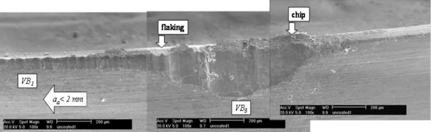
the tool leading edge area or shown by point A at Figure 1. The localization at the leading cutting edge is due to the fact that this area is the frontier of contact (interrup-ted cutting) between tool and workpiece and all cutting loads (mechanical and thermal) are concentrated at this area.
Fig. 2. Flank wear progression at tooth feed of 0.1 mm/tooth.
Fig. 3. Flank wear progression at tooth feed of 0.15 mm/tooth.
The results of testing for cutting conditions as recom-mended by the sensitivity stage are presented in Figures 4 and 6. In Figure 4, tool life (min) is plotted against cutting speed (m/min), and in Figure 6, tool life (min) is plotted against volume of material removed (cm3). From all data plotted in both figures and by utilizing the
multiple regression method [4], the extended Taylor tool life model (T) and the volume of material removed (Q) model are resulted:
6 8
. 2 97 . 2 3 . 3
10 767 .
1 x
a f V
T c z a = (1)
3 96
. 1 98 . 1 2 . 2
10 318 .
3 x
a f V
Q c z a = (2)
From the data plotted in Figure 5, it is recorded that tool life of cutting speeds between 100 – 115 m/min is ranging from 5 to 15 minutes. This value is higher enough to claim that the alloyed carbide tool used in this study is potential to be used for dry end milling of Ti-6242S. This fact is contrary to the results of some pre-vious researchers [5-7] that reported the alloyed carbide tool is not recommended for machining of titanium alloy due to high crater and flank wear rate.
10 100 1000
1 10 100
Tool life (min)
C
u
tt
in
g
s
p
ee
d
(
m
/m
in
).
Experimental
Model
Figure 4. Tool life (min) vs. cutting speed (m/min).
C. Optimum cutting conditions
Once the models are obtained for T and Q, the models can be used to simulate the behaviour various values of cutting conditions. Since we have T (min) and Q (cm3), thus the material removal rate (MRR) can be calculated by (Q/T) (cm3/min).
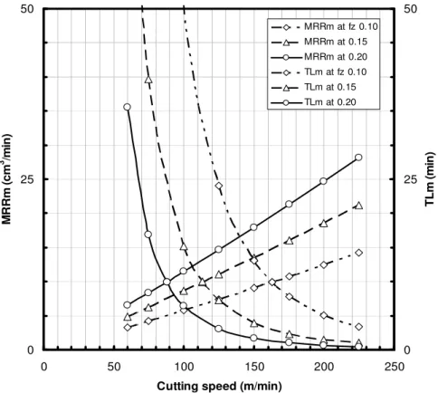
In Figure 7, the T model is used to simulate the results of tool life (TLm) for various cutting speeds and tooth feeds of 0.1, 0.15 and 0.2 mm/tooth. In the similar mea-ning, the Q model is also used to simulate the metal removal rate (MRRm).
From Figure 7, it can be seen that tool life (TLm) is decreasing as the increasing of cutting speed, while the material removal rate (MRRm) shows a contrast beha-viour. The behaviour of tool life curve can be divided into three stages:
Fig. 5. Localized flank wear (VB3) at the tool leading edge area.
10 100 1000
10 100 1000
Volume of material removed (cm3)
C
u
tt
in
g
s
p
ee
d
(
m
/m
in
).
Experimental
Model
Fig. 6. Volume of material removed (cm3) vs. cutting speed (m/min).
decreasing as the increasing of cutting speed and no intersection point between tool life curve and material removal rate curve is found.
2. The regular stage. This stage is the continuation of the linear stage and at all values of tooth feed; the stage is ending at cutting speed of 225 m/min. At this stage tool life is regularly decreasing as the increasing of cutting speed and all tool life curves are intersection with all material removal rate curves. At tooth feed of 0.2 mm/tooth, the intersection point between tool life curve and material removal rate curve is at cutting speed of 88 m/min, at tooth feed of 0,15 mm/tooth is at cutting speed of 113.5 m/min, and at tooth feed of 0.1 mm/tooth is at cutting speed of 163 m/min. Those three points are the points that we consider as the opti-mum cutting condition for the alloyed carbide tool when used to end milling of titanium alloy Ti-6242S under dry machining environment. It is expected that at those three points the best compromise among cutting speed, tool life and metal removal rate can be achieved and thus, the productivity is optimum. Tooth feeds of 0.1, 0.15 and 0.2 mm/tooth are selected for
simulation based on the results of experimental works on the sensitivity and performance stages. 3. The horizontal stage. This stage is the continuation
of the regular stage. It is believed that tool life curve is continuously decreasing even at small gradient and this curve will end at a certain cutting speed in which cutting tool is instantaneously severe damage just after the first contact of inter-rupted cutting (a premature tool breakage or failu-re).
D. Tool wear and wear mechanism
From the study on wear mode and wear mechanism, it can be observed that wear mode of alloyed carbide tool used for cutting below the optimum cutting condition is more on the uniform flank wear (VB1) and its wear mechanism is the adhesive wear.
In the case of cutting at the above of the optimum cutting condition, wear mode is more on the localized flank wear (VB3) and this mode is followed by plastic deformation and brittle fracture (cracking, flaking and chipping). For the wear mechanism, besides adhesive wear (attrition and galling), dissolution-diffusion is also evidenced.
It is believed that the wear mode and its mechanism when machining below the optimum cutting speed are due to mechanical load phenomenon other than thermal load phenomenon when machining above the optimum cutting condition.
From the description in the above, it can be interpreted that the tool failure mode or wear mode, tool wear mechanism and the behaviour of tool performance (the combination among cutting speed, tool life and metal removal rate) are changing at the optimum cutting conditions given by the model. E. Machining simulation
morphology, primary shear angle, contact length and cutting pressure.
In Figures 8, the results of machining simulation on chip morphology and the distribution of temperature are presented. From the shape of chips, it can be observed that the serrated chip as the common chip of titanium alloy is successfully obtained. From the figures, it can be seen and obtained that the higher the cutting speed, the curly the chip curvature, the lower the shear angle and the shorter is the contact length. In the case of temperature, it is
obtained that the higher the cutting speed, the higher is the cutting temperature. In Figure 9, the cutting temperature among three points of the optimum cutting conditions is compared. Those values show that the cutting temperature is the ideal temperature to ensure the occurrence of dissolution-diffusion wear mechanism [7].
0 25 50
0 50 100 150 200 250
Cutting speed (m/min)
M R R m ( c m 3 /m in ) 0 25 50 T L m ( m in )
MRRm at fz 0.10
MRRm at 0.15
MRRm at 0.20 TLm at fz 0.10
TLm at 0.15
TLm at 0.20
Fig. 7. Cutting speed (m/min) vs. Metal Removal Rate Model (MRRm) (cm3/min)
and Tool Life Model (TLm) (m/min).
IV. CONCLUSIONS
At the end of this paper, it can be concluded that the alloyed carbide tool used in this study show a good per-formance when used in end milling of the aeronautical material Ti-6242S under green / dry machining environ-ment. Tool life is recorded ranging from 5 to 15 minutes at cutting speeds of 100–115 m/min, and these cutting speeds is much higher than the common cutting speed of titanium machining using carbide (60 m/min). Although not reported detail in this paper, it can be noted that at the range of speeds, surface topography is found good in term of surface roughness.
In term of the extended Taylor tool life (T) model and the volume of material removed (Q) model, the performance of the alloyed carbide tool can be given by:
6 8 . 2 97 . 2 3 . 3 10 767 . 1 x a f V
T c z a =
3 96 . 1 98 . 1 2 . 2 10 318 . 3 x a f V
Q c z a =
From the models, three optimum cutting conditions are resulted; they are (88 m/min, 0.2 mm/tooth), (113.5 m/min, 0.15 mm/tooth) and (163 m/min, 0.1 mm/tooth). Those three pairs of cutting conditions represent the best
compromise condition among cutting speed, tool life and material removal rate. In the meaning of having further understanding, we note that further study will be carried out to verify whether the optimum cutting condition can also be achieved in lower cutting speed to obtain higher material removal rate and longer tool life by increasing the load of cutting (feed). It is important because higher material removal rate in lower cutting cannot simply be achieved by heavier feeding.
At the optimum cutting conditions, it can be inter-preted that the tool failure mode, tool wear mechanism and the behaviour of tool performance are changing from mechanical load phenomenon to thermal load phe-nomenon. We note that it is natural since the higher the cutting speed the higher is the cutting temperature (ther-mal load).
(a) (b)
(c)
Fig. 8. Chip morphology and temperature distribution of machining simulations. (a) 63 m/min, 0.1mm/tooth, (b) 113.5 m/min, 0.15 mm/tooth, (c) 163 m/min, 0.2 mm/tooth.
Fig. 9. Cutting temperature of optimum cutting speeds in comparison.
V. ACKNOWLEDGMENT
The author would like to thanks the LAMEFIP EN-SAM CER Bordeaux, France for the visiting professor program and the continuation of joint research.
VI. REFERENCES
[1] Sreejith, P.S., Ngoi, B.K.A., “Dry machining: machining of
the future,” J. Mater. Proc. Technol. 101: 287. 2000.
[2] Boyer, R.R., 1996, “An overview on the use of titanium in
the aerospace industry,” Mater. Sci. and Eng. A213: 103 –
114. 1996.
[3] ISO 8688-2, “Tool life testing in milling” – Part 2. End
milling. 1989.
[4] Montgomery, D.C., Design and analysis of experiments. John
Wiley & Sons. 1991.
[5] Freeman, R.M., “The machining of titanium and some of its
alloys,” Ph.D Thesis, University of Birmingham, UK. 1974.
[6] Hartung, P.D, Kramer, B.M., “Tool wear in machining
[7] Dearnley, P.A, Grearson, A.N., “Evaluation of principal wear mechanism of cemented carbide and ceramics used for
machining titanium alloys IMI318,” Mater. Sci. Technol. 2: