BER Analysis of the Effect of Group Delay in RRC
Filter with Marc Technique
Raj Kumar Gupta1, Sudhanshu Singh1, Sangeeta Shekhawat1
1,2,3,4 Assistant Professor, Department of ECE, Amity University Rajasthan, Jaipur India
Abstract: Wide Code Division Multiple Access (WCDMA) is a third generation (3G) wireless based communication system that has higher data rates, high bandwidth and support multimedia communication capabilities for global mobile communications but the performance of WCDMA is debauched with different factors like noise, fading, scattering, interference .This paper investigates the effect of group delay in root raised cosine filter for wideband code division multiple access and bit error rate performance is analyzed with single input single output antenna system and single input multiple outputs antenna system using maximum ratio combining diversity technique by varying the group delay for quadrature phase shift keying(QPSK) and binary phase shift keying(BPSK).
Keywords: WCDMA; root raised cosine filter; group delay; Antenna diversity; Maximum ratio combining.
I. INTRODUCTION
In wireless communication system WCDMA is a technology which is based on the direct sequence spread spectrum transmission scheme, where user information bits are spread over a wide bandwidth. WCDMA uses very high bit rate upto 2 Mbps. In order to support very high bit rates variable spreading factor and multicode connection is used. WCDMA uses chip rate of 3.84 Mcps and a carrier bandwidth of 5MHz [1][2]. When a signal is transmitted from source to destination through the channel, there are some factors which degenerate the performance of signal and these factors are scattering, noise, fading, path loss and interference. In all these factors fading is very unfavorable factor which attenuates the signal strength .One of the most effective techniques to alleviate the effects of fading is diversity combining technique. In this technique: if one signal path experience a intense fade at a particular point of time, there is a possibility to have a strong signal in another path [3]. In this technique receiver uses multiple copies of the same information signal which are transmitted over communication channels. Hemalatha et.al [4] analyzed diversity in CDMA based broadband wireless system and found that the diversity CDMA system with multiple antennas at the transmitter and receiver results better SNR and trimming in the fading and interference. In communication system pulse shaping filter is used to generate band limited channels and reduce inter symbol interference (ISI) arising from multi path signal reflections [5]. The work in the present paper analyzed the performance of SISO and SIMO using MRC technique by varying the group delay (D) of root raised cosine filter in WCDMA system.
The next Section describes the square root raised cosine filter. The maximum ratio combining (MRC) diversity scheme is presented in Section 3. The simulation results and discussion is presented in the Section 4. The last section concludes the paper and presents the future work.
II. SQUARE ROOT RAISED COSINE FILTER
If channels are too narrow, the symbols will be too wide, hence at sampling points there will be signal of the previous and next symbols. This is called Inter-symbol Interference (ISI).One possible solution is to use an Ideal Low Pass Filter (ILPF) to remove ISI and for Narrow bandwidth channel. But it has some problems that it is physically unrealizable and difficult to approximate. One of the solutions is used Raised Cosine (RC) Filters. It is shown by Nyquist that if the frequency characteristic has odd symmetry at the cutoff frequency, the impulse response will have zeros at uniformly spaced intervals. By using RC filter effects of jitter can be minimized and it is much simpler to attain.
One way to achieving square root raised cosine filter is to take square root of the raised cosine filter in frequency domain and use this new filter in the Tx and Rx. This is the so called Root Raised Cosine filter.
The ideal root raised cosine filter, frequency response consists of unity gain at low frequencies and total attenuation at the high frequencies, the square root of raised cosine function in the middle. The width of the middle frequencies is defined by roll off
pulse shaping filter. The group delay influences the size of output as well as order of filter. For minimizing the filter complexity, filter length or number of taps should be minimum as far as possible. There is tradeoff between group delay (D) and interpolation factor (M) for better performance of pulse shaping filter for WCDMA based wireless communication system. So group delay should be minimum for reducing the filter complexity.
N=D*M
(1) N= filter taps
D= group delay M= interpolation factor
The spectrum of square root raised cosine (SRRC) spectrum is given in following equation
2
sin( (1 )) 4 cos( (1 )) ( )
(1 (4 ) )
c c c
c c
t t t
T T T
SRRC t
t t
T T
(2)
Where Tc is the inverse of chip rate.
α= Roll off factor.
III. MAXIMUM RATIO COMBINING
The diversity approach is the solution to improve the performance of system which is affected by fading. In this approach if one signal path experience a intense fade at a particular point of time, there is a possibility to have a strong signal in another path. There are so many diversity approaches such as frequency diversity, time diversity, Antenna diversity and polarization diversity. But one of the most important techniques is antenna diversity. In this approach multiple antennas are placed at the transmitter and/or the receiver [7]. Antenna diversity techniques use some combining approaches like selection combining, maximum ratio combining, and equal gain combining. The antenna diversity approach for single input single output (SISO) and single input multiple outputs (SIMO) are presented below in Fig.2 and Fig.3.
Fig.2 Single Input Single Output Antenna System (SISO)
Fig.3 Single Input Multiple Outputs Antenna System (SIMO)
In maximum ratio combining (MRC) approach, all the branches are used concurrently. Each branch signal is weighted with a gain factor which is proportional to its own signal to noise ratio (SNR). After that, co-phasing and addition operation will be performed. [8]. Fig.4 shows the configuration for a two-branch diversity system. Both the branches are weighted by their respective signal-to-noise ratio and then all the branches are co-phased and added to get the maximum diversity gain. The added signals are used as a received signal and connected to the demodulator [9].
Tx Rx
SNR1
r
1N
SNR2 2r
N
Fig.4 Block diagram of a maximum ratio combining approach
The inputs to the maximum ratio combiner (Fig.4) are both rayleigh distributed signals (with envelopes r1and r2) with additive
independent noise voltage sources n1 and n2. n1and n2are zero mean white gaussian random variables with a variance of N; the
input voltage signal-to-noise ratios are
N
r
SNR
P 2 2 , 1 2 , 1
(3)N
r
SNR
SNR
V P2 , 1 2 , 1 2 ,
1
(4)
The SNR after maximum ratio combining (MRC) requires the evaluation of the instantaneous signal power and noise power. The
amplitude of the signal of interest after MRC at a give time
t
0,V
S,M
t
0 , can be evaluated by multiplying the received signal enveloperr
1andr
2, att
0, by their instantaneous voltage to noise power ratios which when summed gives.
N t r t r N t r t r N t r t r t VSM2 0 2 2 0 1 0 2 0 2 0 1 0 1 0 , (5)
2 2 0 2 2 0 1 2 0 , 0 ,
N
t
r
t
r
t
V
t
P
S M S M(6)
The noise component after MRC at
t
0,V
N,M
t
0 , is also multiplied by the gains in both branches and evaluates after co-phasing and branch addition to
N
t
r
n
t
r
n
N
t
r
n
N
t
r
n
t
V
NM 2 0 11 0 2 2 02 0 1 1 0 ,
(7) The noise power is given by
x x N
x x xN
E
n
n
f
n
dn
N
P
x
2 2
2 2 0 2 2 2 2 0 2 0 1 2 1 2 2 0 1 2 1 2 0 , 0 ,2
N
t
r
n
N
t
r
t
r
n
n
N
t
r
n
E
t
V
t
P
NM NMSignal co-phasing
The middle term evaluates to zero since each noise source is independent of all other signals and has a mean of zero.
2 2 0 2 2 2 2 2 0 1 2 1 0 ,N
t
r
n
E
N
t
r
n
E
t
P
N M
N
t
r
t
r
n
E
N
t
r
n
E
N
t
r
t
P
NM2 0 2 2 0 1 2 2 2 2 0 2 2 1 2 2 0 1 0 ,
2
0 , 2 0 , 0 , 0 , 0
t
V
E
t
V
t
P
t
P
Power
Power
t
SNR
M N M S M N M S Noise SignalPM
2
0 2 2 0 1 2 0 2 2 0 1 0
1
t
r
t
r
N
N
t
r
t
r
t
SNR
MP
(8)
MGC
Output
dB
SNR
1
SNR
2
2 0 2 2 0 1 2 0 2 2 0 1 0 0 1 t r t r N N t r t r t SNR t SNR M M PV
2 2 2 1
1
r
r
SNR
N
PM
(9) 2 2 2 1
1 r r
SNRVM N
(10) IV. SIMULATION RESULTS AND DISCUSSION
Simulation results of varying group delay in RRC filter with maximum ration combining approach for WCDMA system are analyzed in this section. In this approach we use two antennas (nRx1 and nRx2) at the receiver side with different values of group delay (D) in root raised cosine (RRC) filter. The WCDMA system is simulated in MATLAB and To analysis the result of group delay the other factors such as interpolation factor (M) and roll of factor (α) are fixed at M=5 and α=0.22 in RRC filter. The performance of the MRC antenna diversity scheme is analyzed at different values of group delay (D) in RRC filter. The simulation analysis has been carried out using QPSK and BPSK modulation techniques in two cases. Case 1 based on QPSK for MRC and case 2 based on BPSK for MRC.
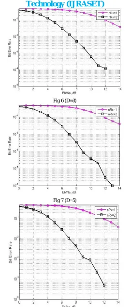
[image:5.612.132.419.544.710.2]Fig 6 (D=3)
Fig 7 (D=5)
[image:6.612.172.441.60.692.2]Fig 9 (D=10)
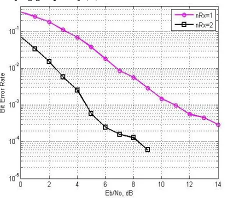
The BER v/s Eb/No relationship for the WCDMA system with nRx= 1,2 is shown in Fig. 5 to Fig.9 with QPSK modulation scheme using MRC technique. As can be seen from Fig.5 in case of nRx=2,initially the BER obtained around 0.4205and at higher value of Eb/No, the achievable BER decreases around 0.0167 for 7 dBEb/No at D=2. At D=3 initially the BER obtained around 0.4164and at higher value of Eb/No, the achievable BER decreases around 0.0135 for 7 dB Eb/No shown in Fig.6 for nRx=2. From Fig.7 initially the BER obtained around 0.4158 and at higher value of Eb/No, the achievable BER decreases around 0.0100 for 7 dB Eb/No at D=5. At D=7 initially the BER obtained around 0.4194 and at higher value of Eb/No, the achievable BER decreases around 0.0108 for 7 dBEb/No shown in Fig.8. From Fig.9 initially the BER obtained around 0.4209and at higher value of Eb/No, the achievable BER decreases around 0.0129 for 7 dBEb/No at D=10.
It is observed from the simulation that the BER is gradually decrease when group delay varying from 2 to 5 When group delay varying from 5 to 10, BER is increased again. The optimum value of group delay was found to be 5, at which both SISO and SIMO WCDMA system gave best performance [10].
B. Case-2 BER analysis of BPSK by varying group delay (D)
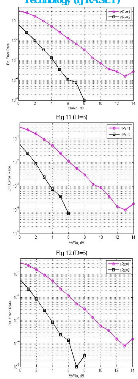
[image:7.612.195.420.506.704.2]Fig 11 (D=3)
Fig 12 (D=5)
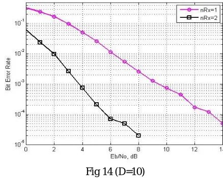
[image:8.612.186.418.68.704.2]Fig 14 (D=10)
The BER v/s Eb/No relationship for the WCDMA system with nRx= 1,2 is shown in Fig. 10 to Fig.14 with BPSK modulation scheme using MRC technique. As can be seen from Fig.10 in case of nRx=2,initially the BER obtained around 0.0714and at higher value of Eb/No, the achievable BER decreases around 0.0002 for 7 dB Eb/No at D=2. At D=3 initially the BER obtained around 0.0626 and at higher value of Eb/No, the achievable BER decreases around 0.0001 for 7 dBEb/No shown in Fig.11 for nRx=2. From Fig.12 initially the BER obtained around 0.0564and at higher value of Eb/No, the achievable BER decreases around 0 for 7 dBEb/No at D=5. At D=7 initially the BER obtained around 0.0573and at higher value of Eb/No, the achievable BER decreases around 0.0001 for 7 dB Eb/No shown in Fig.13. From Fig.14 initially the BER obtained around 0.0614 and at higher value of Eb/No, the achievable BER decreases around 0.0003 for 7 dBEb/No at D=10.
It is observed from the simulation that the BER is gradually decrease when group delay varying from 2 to 5 When group delay varying from 5 to 10, BER is increased again. The optimum value of group delay was found to be 5, at which both SISO and SIMO WCDMA system gave best performance [11].
V. CONCLUSION
The work in this paper analyzed the joint effect of maximum ratio combining diversity approach with root raised cosine (RRC) filter to reduce the effect of inter symbol interference , inter-intra cell interference and fading. The increasing delay in RRC filter increases the complexity in the system and decreases the BER performance for both SISO and SIMO WCDMA system. It was observed from the simulation result that the SIMO system gave better performance in comparison to the SISO system. Results also conclude that BPSK modulation technique is better compare to QPSK for SISO and SIMO. In future work the same analysis will be carried out for MIMO system and implement on FPGA.
REFERENCES
[1] Olavarrieta L.D., “Wireless communications education: A Guide to Important Topics, Microwave Review, November, 2005.
[2] Prasad R. and Ojanpera T., “An overview of CDMA evolution towards wideband CDMA,” IEEE communication survey, Vol.1,pp.2-29, fourth quarter 1998. [3] Proakis J.G.: Digital Communications, McGraw-Hill, 1995.
[4] Hemalata.M et.al, “Diversity analysis in CDMA based broadband wireless system ”, Research Journal of Applied Sciences, Engineering and Technology 4(6): 660-663, 2012.
[5] Kang A.S and Sharma V, “Analysis of Simulation parameters of pulse shaping FIR filter for WCDMA”, International Journal of Advancements in Technology, ISSN 0976-4860, Vol. 1, No. 1 ,June 2010 .
[6] Kang A. S. and Sharma V, “Study of Spectral Analysis of Filters in Cellular Communication Systems”,in Proceedings of IEEE International Conference on advance Computing Conference, March 2009.
[7] Sedani B.S;Kulkarni G.R.; “Implementation of quality based algorithm for Wimax simulation using SISO and MIMO techniques”,Global journal of researches in engineering,Vol.10,no.4,pp. 106-112,2010.
[8] Zhou h. and Okamoto k., “Comparison of code combining and MRC diversity reception in mobile communications”, IEEE Wireless Communications and Networking Conference, 2004, Atlanta, USA,Vol.2,pp 908-913, 2004.
[9] Gordon S.L., “Principle of mobile communication,” Kluwer academic, boston, 1996.
[image:9.612.193.412.77.252.2]