5
IV
April 2017
Technology (IJRASET)
Circularly Polarized Multi Band Patch Antenna for
High Frequency Wi-Fi and Wi-MAX Application
Simulated with CST Studio Suite
Dr. D. Selvaraj1, Kavianand G2, Karthikeyan P3, Balaji M4, Gowri Ganesh K5
1
Professor, 2,3,4,5UG Scholar, Department of Electronics and Communication Engineering
Panimalar Engineering College, Chennai 600123, Tamil Nadu, India.
Abstract: A circularly polarized multi band patch antenna for high frequency application was proposed. The main purpose of this antenna is for wireless communication mainly Wi-Fi and WiMAX applications and also satisfy the bandwidth quotation of 5G application. In our work, we presented a concept of designing antenna that can work simultaneously 1.1 / 2.8 / 3.3 / 5.7 / 6 and 7.4 GHz for multiple wireless and Network applications. The special shaped patch antenna is used to attain multiple bands. It is an I shaped antenna, along with a tilted and inverted two u shaped antenna patched over it. One thick inverted U shaped antenna, tilted with 450 and another is of thin inverted u shaped antenna that tilted 900 in accordance with a previous tilted patch, that is about 450 to I shaped antenna but on opposite side of thick patch. It is connected to thick U shaped patch not with an I shaped patch. All rotation and tilting are done in horizontal axis. A 6*6 square metallic patch antenna was designed in back for simple frequency selecting purpose. Those Metallic patch surfaces behave as a simple frequency select surface (FSS). The main purpose of tis antenna is to achieve a frequency range of 5.7/6 GHz which are used for WiMAX application all over the world but the use depends upon the countries and 7.4 GHz which is proposed by USA for 5G applications.
Keywords: Multiband antenna; Circularly polarized antenna; Wi-Fi and WiMax application; proposed 5G bandwidth; Patch antenna; CST studio suite;
I. INTRODUCTION
In 1886 Hertz built the first radio link service which acts as a milestone for the antenna development, since that the most critical technology involved in antenna design, which helped people to get connected globally. Due to the rapid development in the radio technology, several advancements happened in antenna technology for the past 130 years. We made our own advancement that, a circularly polarized multi band antenna was proposed. The main purpose of this antenna is for wireless Wi-Fi and WiMAX applications
and also a proposed 5G bandwidth.
Wireless applications are going to rule the communication systems of next generations, hence a lot of research and development is going on in the wireless communication systems, concentrating on multi bandwidth and multi-functional antenna systems. In this antenna a multiple band, say six bands are identified for primary use.
Since the linearly polarized (LP) antennas have their own drawbacks, circularly polarized (CP) antennas took its place over time, in the modern wireless communication systems. There available a multiple patch antenna separately for each frequency application but not on a single antenna. So we are here to deal with a single patch antenna, that can handle all threads over distinguished different frequency simultaneously.
Technology (IJRASET)
design must be smaller and less complicated, which tend to be the motive of our design.
II. DESIGNING OF ANTENNA
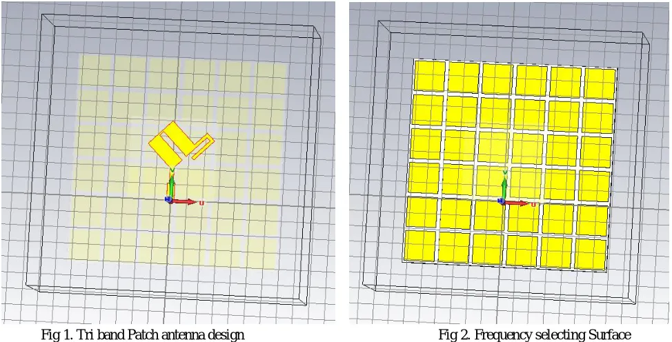
The proposed antenna's design could be carried oud aa a three step procedure, where Preperm 1000 lossy of 1.53 mm thickness and a dielectric constant of 10. On which the multi-band CP antenna is suspended. The Preperm 1000 lossy is selected mainly for its variable dielectric constant property. The next step is designing the metallic Frequency Selecting surface, which is carried out by referring the reflection phase characteristics. Tri band patch antenna design is shown in Fig 1.
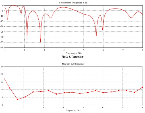
[image:3.612.63.550.229.477.2]The final stage is designing a patch antenna which is to be held at a height h above the FSS. The Frequency selecting surface composed designed in a 6*6 layout each is of square shaped that overall comprises of 36 unit cells. It is designed on a Taconic RF-35 substrate. Its thickness is 1.53 mm, dielectric constant is 3.4 and a loss tangent of 0.002. Consider L to be the horizontal (x- plane) distance between the bottom edge of antenna substrate and FSS substrate. The Frequency Selecting Surface in an antenna is shown in Fig.2 which is simulated by using CST Studio Suite.
Fig 1. Tri band Patch antenna design Fig 2. Frequency selecting Surface
A. Tri Band Patch Antenna Design
1.1 GHz, 2.8 GHz, 3.3 GHz are the three frequency bands that are attained by using and special shaped patch antenna. It is an I shaped antenna, along with a tilted and inverted two u shaped antenna patched over it. One thick inverted U shaped antenna, tilted with 450 and another is of thin inverted U shaped antenna that tilted 900 in accordance with a previous tilted patch, that is about 450 to I shaped antenna but on opposite side of thick patch. It is connected to thick U shaped patch not with an I shaped patch. Fig.1 shows the structure of Tri-band patch antenna. All rotation and tilting are done in horizontal axis. The final optimized geometrical structure of the tri-band CP patch antenna was obtained through simulations with CST Studio Suite.
B. Frequency Selecting Surace Design
The geometry of the square unit cell and the patch implemented are 19.55 mm and 22.185 mm respectively. The unit cell is designed with calculated reflection phase, that throttles between +90o and –90o with
1) 5.7–5.45 GHz, as its frequency range with 5.7 GHz resonant frequency.
2) 6.15–5.85 GHz, as its frequency range with 6 GHz resonant frequency.
3) 7.75–7.15 GHz, as its frequency range with 7 GHz resonant frequency.
The overall size of the frequency selecting surface is 135.2 × 135.2 mm. A wave port which excites the CP patch was placed above the frequency selecting surface(FSS), at an altitude of 28.2 mm. The Fig.2 Shows the design of FSS.
Technology (IJRASET)
selecting surface. The characteristics of antenna for various unit cells of different number and character were studied. 6 × 6 metal patches were inferred along horizontal (x axis) and vertical axis (y axis) to have a better output. Finally, the necessary alterations and changes are made in position and dimensions antenna are made to get the best results at the required frequencies : 1.1 GHz, 2.8 GHz, 3.3 GHz, 5.7 GHz, 6 GHz and 7.4 GHz
III. ANALYSIS OF DESIGNED ANTENNA
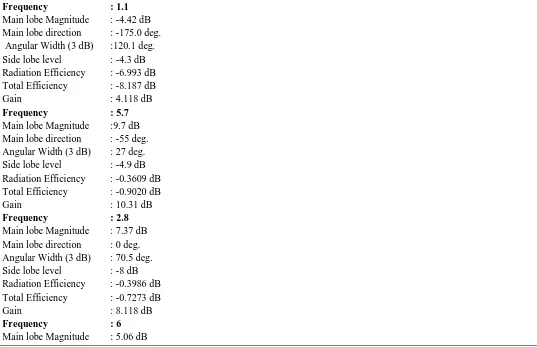
S-parameter, Efficiency and VSWR (Voltage Standing Wave Ratio) is considered as the most important parameter of the antenna. The S-parameter and Efficiency are shown in Fig.3 and Fig.4 respectively.
[image:4.612.52.562.178.577.2]Fig 3. S-Parameter
Fig 4. Maximum gain over frequencies
The fig.3 shows that the radiation of antenna is best at implied frequencies: 1.1/ 2.8/ 3.3/ 5.7/ 6 and 7.4 GHz. The Fig.4 shows the maximum gain of the antenna on all frequencies. It is to be noted that the gain is high on desired frequency than other frequencies. The relationship between the output and the input terminals or ports can be analysed and described by an S-parameter. In antenna design return loss is a highly considerable parameter, which gives the magnitude of the reflected power from the antenna, if the parameter hits 0dB then all the power is reflected and no sign of power radiation.
The remaining power is accepted by antenna itself, so it is neither absorbed nor radiated by the antenna. Practically most of the power delivered to the antenna gets radiated hence VSWR directly impacts on the return loss of the antenna. The theoretical (simulated) and the practical return loss is shown in Fig. 3. the theoretical and measured results comes nearly close together, with some inevitable refinements with corresponding boundary conditions in the simulation environment.
Technology (IJRASET)
[image:5.612.314.548.100.344.2]shown a significant Multi-Band operation in the frequencies: 1.1GHz, 2.8GHz, 3.3GHz, 5.7GHz, 6GHz and 7.4GHz.
[image:5.612.71.297.103.342.2]Fig 5. Farfield directivity plot for 1.1 GHz Fig 6. Farfield directivity plot for 2.8 GHz
Fig 7. Farfield directivity plot for 3.3 GHz Fig 8. Farfield directivity plot for 5.7 GHz
[image:5.612.63.547.118.515.2] [image:5.612.67.542.342.642.2]Technology (IJRASET)
Fig 9. Farfield directivity plot for 6 GHz Fig 10. Farfield directivity plot for 7.4 GHz The considered parameters for the designed antenna is tabulated below.
Frequency : 1.1
Main lobe Magnitude : -4.42 dB Main lobe direction : -175.0 deg. Angular Width (3 dB) :120.1 deg. Side lobe level : -4.3 dB Radiation Efficiency : -6.993 dB Total Efficiency : -8.187 dB Gain : 4.118 dB
Frequency : 5.7
Main lobe Magnitude :9.7 dB Main lobe direction : -55 deg. Angular Width (3 dB) : 27 deg. Side lobe level : -4.9 dB Radiation Efficiency : -0.3609 dB Total Efficiency : -0.9020 dB Gain : 10.31 dB
Frequency : 2.8
Main lobe Magnitude : 7.37 dB Main lobe direction : 0 deg. Angular Width (3 dB) : 70.5 deg. Side lobe level : -8 dB Radiation Efficiency : -0.3986 dB Total Efficiency : -0.7273 dB Gain : 8.118 dB
Frequency : 6
[image:6.612.38.575.373.720.2]Technology (IJRASET)
Main lobe direction : 60 deg. Angular Width (3 dB) : 41.3 deg. Side lobe level : -3.2 dB Radiation Efficiency : -0.3734 dB Total Efficiency : -0.7307 dB Gain : 8.104 dB
Frequency : 3.3
Main lobe Magnitude : 8.96 dB Main lobe direction : 25 deg. Angular Width (3 dB) : 67.7 deg. Side lobe level : -9.6 dB Radiation Efficiency : -0.1467 dB Total Efficiency : 0.1629 dB Gain : 8.958 dB
Frequency : 7.4
Main lobe Magnitude : 8.09 dB Main lobe direction : -70 deg. Angular Width (3 dB) : 35.6 deg. Side lobe level : -2.6 dB Radiation Efficiency : -0.49 dB Total Efficiency : -1.625 dB Gain : 8.677 dB
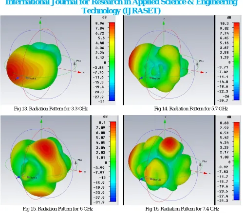
The radiation pattern of an antenna for different frequencies are shown below in 3D model diagram. These 3D models are shown below.
[image:7.612.61.558.436.697.2]
Technology (IJRASET)
Fig 13. Radiation Pattern for 3.3 GHz Fig 14. Radiation Pattern for 5.7 GHz
Fig 15. Radiation Pattern for 6 GHz Fig 16. Radiation Pattern for 7.4 GHz
IV. CONCLUSION
The Circularly Polarized Multi band patch antenna for high frequency Wi-Fi and WiMAX Application and proposed 5G frequency range was designed, fabricated and characterized. The same is simulated using a simulation tool named CST Studio suite. In this antenna the six frequency bands was achieved. For NFC application 1.1 GHz is used, WLAN applications the frequency band of 2.8 / 5.7 / 6 GHz and for WiMAX applications the frequency band of 3.3 GHz was achieved effectively with high efficiency. It is to be noted that proposed 5G bandwidth of 7.4 GHz is also achieved.
The performance properties of the proposed antenna are analysed for the optimized dimensions and the proposed antenna was designed successfully.
REFERENCES
[1] T. T. Le and H. C. Park, “Very simple circularly polarised printed patch antenna with enhanced bandwidth,” Electron. Lett., vol. 50, no. 25, pp. 1896–1898, 2014.
[2] F. Yang and Y. Rahmat-Samii, “A low profile single dipole antenna radiating circularly polarized waves,” IEEE Trans. Antennas Propag., vol. 53, no. 9, pp. 3083–3086, 2005.
[3] Hoang, The Viet, et al. "Quad-Band Circularly Polarized Antenna for 2.4/5.3/5.8-GHz WLAN and 3.5-GHz WiMAX Applications." IEEE Antennas and Wireless Propagation Letters 15 (2016): 1032-1035.
[4] S. Verma and P. Kumar, “Compact triple-band antenna for WiMAX and WLAN applications,” Electron. Lett., vol. 50, no. 7, pp. 484–486, 2014.
Technology (IJRASET)
Electron. Lett., vol. 49, no. 25, pp. 1597–1598, 2013.
[6] S. Gao, Q. Luo, and F. Zhu, “Circularly polarized antennas,” Wiley-IEEE Press, New York, November 2013.
[7] J. G. Baek and K. C. Hwang, “Triple-band unidirectional circularly polarized hexagonal slot antenna with multiple L-shaped slits,” IEEE Trans. Antennas Propag., vol. 61, no. 9, pp. 4831–4835, 2013.
[8] X. L. Bao and M. J. Ammann, “Printed triple-band circularly polarised antenna for wireless systems,” Electron. Lett., vol. 50, no. 23, pp. 1664–1665, 2014. [9] T. V. Hoang and H. C. Park, “Very simple 2.45/3.5/5.8 GHz triple-band circularly polarised printed monopole antenna with bandwidth enhancement,” Electron.
Lett., vol. 50, no. 24, pp. 1792–1793, 2014.
[10] K. Agarwal, Nasimuddin, and A. Alphones, “RIS-Based compact circularly polarized mircostrip antennas,”IEEE Trans. Antennas Propag., vol. 61, no. 2, pp. 547–554, 2013.
[11] H. L. Zhu, S. W. Cheung, K. L. Chung, and T. I. Yuk, “Linear-to-circular polarization conversion using metasurface,” IEEE Trans. Antennas Propag., vol. 61, no. 9, pp. 4615–4623, 2013.
[12] S. Clavijo, R. E. Diaz, and W. E. McKinzie, “Design methodology for sievenpiper high-impedance surfaces: An artificial magnetic conductor for positive gain electrically small antennas,” IEEE Trans. Antennas Propag., vol. 51, no. 10, pp. 2678–2690, 2003.
[13] A. E. I. Lamminen, A. R. Vimpari, andJ. Saily, “UC-EBG on LTCC for 60-GHz frequency band antenna applications,” IEEE Trans. Antennas Propag., vol. 57, no. 10, pp. 2904–2912, 2009.
[14] K. Agarwal, Nasimuddin, and A. Alphones, “Triple-band compact circularly polarised stacked microstrip antenna over reactive impedance meta-surface for GPS applications,” IET Microw. Antennas Propag., vol. 8, no. 13, pp. 1057–1065, 2014.
[15] Tuan Le, Tu, Viet Hoang The, and Hyun Chang Park. "Simple and compact slot‐patch antenna with broadband circularly polarized radiation." Microwave and Optical Technology Letters 58.7 (2016): 1634-1641.
[16] Tang, Hongyan, et al. "Compact broadband CP monopole antenna with tilted branch." Electronics Letters 52.21 (2016): 1739-1740.
[17] Bernard, Loïc, G. Chertier, and Ronan Sauleau. "Wideband circularly polarized patch antennas on reactive impedance substrates." IEEE Antennas and Wireless Propagation Letters 10 (2011): 1015-1018.
[18] Chi, Li-Pin, et al. "A wideband wide-strip dipole antenna for circularly polarized wave operations." Progress In Electromagnetics Research 100 (2010): 69-82.
[19] Reddy, V. V., and N. V. S. N. Sarma. "Triband circularly polarized Koch fractal boundary microstrip antenna." IEEE antennas and wireless propagation letters 13 (2014): 1057-1060.
[20] Park, Hyun Chang. "Very simple 2.45/3.5/5.8 GHz triple-band circularly polarised printed monopole antenna with bandwidth enhancement."Electronics Letters 50.24 (2014): 1792-1793.
[21] Park, Hyun Chang. "Very simple 2.45/3.5/5.8 GHz triple-band circularly polarised printed monopole antenna with bandwidth enhancement."Electronics Letters 50.24 (2014): 1792-1793.
[22] Sree, Y. Navya, et al. "Multiband circularly polarized symmetrical fractal boundary microstrip antenna for microwave applications." Advances in Computing, Communications and Informatics (ICACCI), 2015 International Conference on. IEEE, 2015.
[23] Kuo, Chi-Jung, et al. "A novel wideband circularly polarized dual-fed slot antenna with microstrip feeding network." Journal of Electromagnetic Waves and Applications 30.2 (2016): 175-187.
[24] Prajapati, Pravin R., M. Srinivasulu, and M. V. Kartikeyan. "Realization of circular polarized microstrip antenna with Arc-slot fractal geometry."Microwave, Optical and Communication Engineering (ICMOCE), 2015 International Conference on. IEEE, 2015.
[25] T. V. Hoang and H. C. Park, “Very simple 2.45/3.5/5.8 GHz triple-band circularly polarised printed monopole antenna with bandwidth enhancement,” Electron. Lett., vol. 50, no. 24, pp. 1792–1793, 2014.
[26] Zhangfang, Hu, et al. "Design of a modified circular-cut multiband fractal antenna." The Journal of China Universities of Posts and Telecommunications 23.6 (2016): 68-75.
[27] Ta, Son Xuat, Ikmo Park, and Richard W. Ziolkowski. "Circularly polarized crossed dipole on an HIS for 2.4/5.2/5.8-GHz WLAN applications." IEEE Antennas and Wireless Propagation Letters 12 (2013): 1464-1467.
[28] Cai, Tong, et al. "Low-profile compact circularly-polarized antenna based on fractal metasurface and fractal resonator." IEEE Antennas and Wireless Propagation Letters 14 (2015): 1072-1076.
[29] Qing, Xianming, and Zhi Ning Chen. "A compact circularly polarized slotted patch antenna for GNSS applications." IEEE Transactions on Antennas and Propagation 62.12 (2014): 6506-6509.
[30] Ta, Son Xuat, and Ikmo Park. "Dual-band operation of a circularly polarized radiator on a finite artificial magnetic conductor surface." Journal of Electromagnetic Waves and Applications 28.7 (2014): 880-892.
[31] Saurav, Kushmanda, et al. "Multiband circularly polarized cavity-backed crossed dipole antenna." IEEE Transactions on Antennas and Propagation63.10 (2015): 4286-4296.
[32] Saurav, Kushmanda, et al. "Multiband circularly polarized cavity-backed crossed dipole antenna." IEEE Transactions on Antennas and Propagation63.10 (2015): 4286-4296.