6
I
January 2018
Automated Match Box Base Folding
M. Periyasamy1, M. Ramya2, V. MahaVishnu3, M. Sabarimuthu4
1
UG Scholar, Department of EEE, Kongu Engineering College Perundurai, Erode-638 060
2
UG Scholar, Department of EEE, Kongu Engineering College Perundurai, Erode-638 060
3
UG Scholar, Department of EEE, Kongu Engineering College Perundurai, Erode-638 060
4
Assistant Professor, Department of EEEB Kongu Engineering College,Perundurai,Erode-638 060
Abstract: The economic development of a country is measured on the basis of the industrialization. Even though the technology has been developed worldwide, still there is a problem, which includes the production of matchbox base folding is done manually. With the increased number of workers for matchbox production, but their production output is very low. This also increases the risk of various health problems to the workers. Since the process is continuously repeated, it filling matchsticks may create stress to workers. In order to overcome these issues, we have designed an automated match box base folding. This paper describes about how automated matchbox folding box has been designed. Through this project, the productivity of company increases with less time consumption. It reduces the large amount of labor cost and also decreases stress to workers.
Keywords: DC motor, conveyor belt, stepper motor, microcontroller
I. INTRODUCTION
Match industries are utmost necessity in the everyday life of human beings. The origin of the match industry dates back to new stone-age. Match industry has mass production and provides employment opportunities to the society. It plays a vital role in building up the economic structure of the society. Sweden is the famous and oldest manufacturer of match industry. The major market areas are Delhi, Gujarat and Rajasthan. The small match factories could not meet the total requirements of the country. However, India began to import matches from Sweden and Japan. Packing is the final stage process in the manufacturing industry which is the important process ,as it determines the production rate of a manufacturing industry. Hence the production rate of the company decreases and it also has some limitations such as migration of labors, hike for increase in wages, handling of those sticks directly in hand may serious health hazards to the labor. So we created the automated matchbox base folding machine at low cost. Senthil et all[1]designed the automatic match box filling machine with the production rate of the company increases. The production cost of the product has been decreased. There is no need of thinking about the hikes on increases in wages and the absence of labor doesn't affect the productivity of the company. Mahajan et all[2]proposed an easy T-shirt Folding machine is an automatic motor controlled t-shirt folding machine to fold T-shirts merely by pressing a button. Here they used four DC gear motors to control the motion of the folding part and rotates according to the program which uses microcontroller. The microcontroller controls the overall motion of the folding Senthil et all[3] proposed an "Automatic match box filling machine "which deals about automatic filling of match sticks in the match box which increases the production and decreases the cost. Hani Buri [4] proposed about domain folding of plate structures. This makes complex geometries developed by economic ways.
Mahajan et all[5] proposed T-shirt folding machine discussed about T-shirts automatically using DC gear motors. This provide easy and full automatic technique to fold t-shirts and reduce human works.
II. PROPOSED METHOD
The proposed method designed an automated folding match box base and apply glue on it together, at low cost for middle class people with the advantages of
Reduce manual works Increase perfections
Time and enrgy consumption
Figure 2.1 Proposed Block Diagram
The components required for the proposed system includes: DC motor, stepper motor, conveyor belt and microcontroller.
A. DC Motor
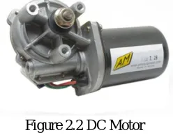
A DC motor is mechanically commutated electric motor powered from DC current shown in the figure 2.2.The stator is stationary in space by definition and therefore the current in the rotor is switched by the commutator to also be stationary in space. The relative angle between the stator and rotor magnetic flux is maintained near 90 degrees, which generates the maximum torque. DC motor has rotating armature winding .For permanent magnetnon -rotating armature magnetic field and a static field winding are present.
Figure 2.2 DC Motor
The speed of a DC motor can be controlled by changing the voltage or current applied to the armature. Modern DC motors are often controlled by power electronics system called DC drives. We have used 12V DC motor with a speed range of 60rpm . The motor operation is based on principle called simple electromagnetism. A simple 2-pole DC electric motor(here red represents a magnet or winding with a "North Polarization " while green represents a magnet or winding with a "South "polarization).
Figure 2.3 DC Motor working
Every DC motor has six basic parts namely: axle, rotor, stator, commutator, field magnet and brushes. In most common DC motors the external magnetic field is produced by high -strength permanent magnets. The stator is the stationary part of the motor where as the rotor is rotating part. The rotor consists of core winding, which connects electrically to the commutator. DC motor working is shown in figure 4.2
B. Operation
[image:3.612.263.375.494.580.2]C. Stepper Motor
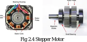
[image:4.612.238.417.132.219.2]A stepper motor is a brushless DC motor that divides a full rotation into number of equal steps. Brushed DC motors rotate continuously, when DC voltage is applied to their terminals. The stepper motor converts a train of input pulses into an increment in the shaft position shown in figure 2.4. Each pulse moves the shaft through a fixed angle.
Fig 2.4 Stepper Motor
D. Operation
Stepper motor consists of electromagnets arranged around a central gear-shaped piece of iron. The electromagnets are energized by an external drive circuit or a microcontroller. To make the motor shaft turn first, one electromagnet given power, which magnetically attracts the gear teeth? When the gear teeth are aligned to the first electromagnet, they are slightly offset from the next electromagnet. This means that when the next electromagnet is turned on and the first is turned off, the gear rotates slightly to align with the next one and the process get repeats. Each rotation is "step" with an integer number of steps making a full rotation. Bipolar motors have a single winding per phase. The current in a winding needs to be reversed in order to reverse a magnetic pole. The windings obtained are better utilized and more powerful than a unipolar motor of the same weight. This is due to the physical space occupied by the windings. Stepper motor is strongly dependent on the driver circuit. To overcome the inductance and the switch the windings quickly, one must increase the drive voltage. This leads to the necessity of limiting the current with the high voltage or may otherwise induce.
E. Actuators
An actuator is a component of a machine that is responsible for moving or controlling the mechanism or system. An actuator requires a control signal and a source of energy. The source may be electric current, fluid pressure, or pneumatic pressure. When the control signal is received , the actuator responds by converting the energy into the mechanical motion shown in figure 2.5. An electric actuator is powered by a motor that converts electrical energy to mechanical torque. Some actuators arte intrinsically linear, such as piezoelectric actuators. conversion between circular and linear motion is commonly made via., few simple types of mechanism namely screw, wheel and axle.
Figure 2.5 Actuators internal diagram
Performance metrics for actuators include speed, acceleration ,force, energy efficiency and considerations such as mass, volume, operating conditions, durability and so on.,
F. Conveyor Belt
[image:4.612.233.384.483.568.2]G. Microcontroller
[image:5.612.227.385.119.228.2]The PIC 16f877 is one of The latest products from Microchip. I t contains all features which get dumped into a single chip which is used for specific application. The pin configuration is shown in figure 2.6
Figure 2.6 Pin configuration of 16F877
III. WORKING PRINCIPLE
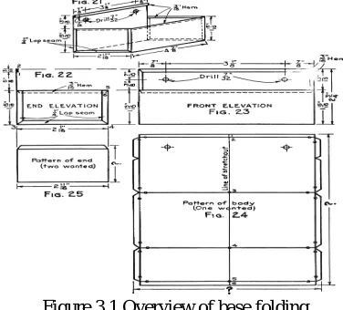
[image:5.612.210.398.316.486.2]The base of the match box is placed on the metal sheet. The four slides\corners of the sheet starts folding automatically when the person presses the centre portion of the base. The two crocodile folding pins are used to complete the process. The process involved in folding are shown in figure 3.1.
Figure 3.1 Overview of base folding
IV. DESIGN CALCULATION
A. DC Motor Power Calculation
Consider a total mass operated by a DC Motor is 650 grams Total mass= 250+400= 650gms (approx.)(1)
We know that acceleration due to gravity in terms of meter per seconds square Acceleration = 9.81m/s2 (2)
From newton’s law of motion, Force=Mass*Acceleration (3)
Substitute(1)&(2)in(3)
Force=650*9.81=6.38N (4) Torque = Force*distance (5) Distance between linear stand, d=0.025m (6)
(or)
0.1595 kg.cm
Let us take speed of a dc motor
Speed,N = 100rpm (8)Power= (2*π*N*T)/60 (9) Substitute (7)&(8) in (9)
B. Actuator Power Calculation
Data from Specifications..,
1) Inpu Voltage :12 V
2) Max.Push Load: 150
3) Max.Pull Load : 1200
4) Speed N : 5.7mm/sec
5) At No Load : <0.5
6) At Max Load : 3A Pmax=V *I max(11) Substitute (11)&(12) in (13) Pmax =12*3
=36W/0.048HP (12)
V. ESTIMATION COST
Maintenance Cost:
(Depends upon Maintenance) Power consumed by Actuators : 96 W Power Consumed by DC Motor: 8 W ---
Operating Cost:
250W*8hr=2000W/Day Wattage Used per Month: 2KW*30= 60 Units Approx. cost: 60*3=rs.180
VI. HARDWARE IMPLEMENTATION
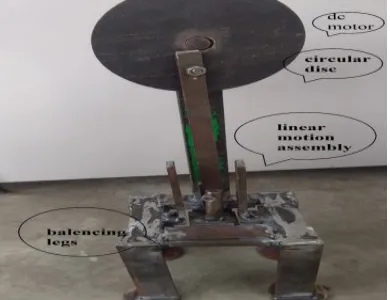
[image:6.612.208.403.475.625.2]The hardware implementation were shown in figure 6.1.Here the balancing legs provides the enough mechanical support to balance on its own. The DC motor is attached to the circular disc.The hardware works on Crank Shaft principle which converts rotatry motion into linear motion.
Figure 6.1 Hardware Implementation
VII. CONCLUSION AND FUTURE SCOPE
REFERENCES
[1] Mukesh P. Mahajan ,Srishti Prasad TejalBinnar, Nashik Monika Tamb, “Automatic T shirt Folding ” International Journal of Computer Applications., (0975 – 8887) Volume 162 – No 10, March 201
[2] Shriraman, T & S, Senthil&Vellaichamy, Ragavanandham,An innovative design of automatic match box filling machine. International Journal of Applied Engineering Research. 10. 3882.June 201
[3] Masahirotaketsugu,Kunioniuchi,yoshiharukushiya,"New box making machine” Mitsubishi heavy industries, ltd.Technical review vol. 42 no. 1 (Feb. 2005 [4] Suraj Shah, Utkarsha Mahajan,” Automatic cloth folding and colour based sorting mechanism” IJTRE,Volume 2, Issue 7, March-2015 .
[5] N.Gomesh, Y.M.Irwan,” Photovoltaic powered T-shirt folding machine” Conference Paper in Energy Procedia ,February 2013. [6] Deepak Shroff, Paresh Somani.” Automatic T-shirt folding machine”.