Thermal Analysis on a Finned Tube Heat
Exchanger of a Two Stage
Air Compressor
Sikindar Baba.Md#1, Nagakishore.S#2,Prof.M.Bhagvanth Rao#3
1
Associate Professor,Department of Mechanical Engineering, Anurag Group of Institutions & Research
Scholar,JNTUH,Hyderabad
2
Associate Professor,Department of Mechanical Engineering, DBS College of Engineering & Technology
3
Director&Professor, Anurag Group of Institutions,Hyderabad
Abstract: Compressors are intended to compress a substance in a gaseous state. Air is compressed in more than one stage when high pressure ratio is required in view of reducing the power input to the compressor.In almost all multi stage applications, air will be cooled between stages which is also known as intercooling.With intercooling, the compression more closely approximates an isothermal compression with resulting lower power requirement. Intercooler is basically a heat exchanger, which is used to cool the compressed air between stages. In the present work, thermal analysis has been done on finned tube heat exchanger (Intercooler of two stage air compressor). Experimental analysis was done on the intercooler (Finned tube heat exchanger) model for the particular pressure ratio. For the finned tube, inside and outside convection heat transfer coefficients are estimated based on the experimental data.Theoretical analysis was done to estimate the heat transfer rate at different sections of the bare tube as well as at the sections where the fins are present. Modified Bessel’s functions of the first and second kind were calculated for the annular fin of rectangular profile model and temperature distribution over each fin was calculated. Finite Element Analysis was done using ANSYS software.
Temperature distribution at different sections and total heat flow is estimated for the finned tube with fins of rectangular profile and with fins of triangular profile. A comparison has been made among experimental data, theoretical data and finite element analysis.
Keywords: Extended surfaces, Heat Transfer, Bessel’s function, Temperature distribution, Intercooler.
1. INTRODUCTION
Thermal Analysis is also often used as a term for the study of heat transfer through structures. Many of the basic engineering data for modeling such systems comes from measurements of heat capacity and thermal conductivity. A reciprocating compressor or piston compressor is a positive-displacement compressor that uses pistons driven by a crankshaft to deliver gases at high pressure. The intake gas enters the suction manifold, then flows into the compression cylinder where it gets compressed by a piston driven in a reciprocating motion via a crankshaft, and is then discharged. Applications include oil refineries, gas pipelines, chemical plants, natural gas processing plants and refrigeration plants.
commonplace in recent years for the analysis of most of the systems which are subjected to different conditions.
2.SCOPE OF WORK
In the present problem, to analyze a finned tube heat exchanger, Intercooler of a Two stage reciprocating air compressor is considered. Intercooler consists of 20 fins of rectangular cross section, which are also known as annular fins of rectangular profile. An experiment was conducted on the compressor at different pressure ratio and temperature of air entering and leaving the intercooler was measured. The main objective of this work is to approximate the inside convective heat transfer coefficient and outside convective heat transfer coefficient. Temperatures at different sections of the finned tube is measured by using Infrared Thermometer. ANSYS is used to analyze the temperature distribution and heat flow for finned tube with fins of rectangular profile and fins of triangular profile.
3. EXPERIMENTAL DETAILS
3.1. Specifications of Finned tube Heat
Exchanger(Intercooler): Innerdiameter of Bare tube:34.65 × 10⁻³
m Outer diameter of Bare tube:41.65 × 10⁻³
m Tube material:Aluminium
Length of Intercooler:166.18 × 10⁻³
m No. of fins:20
Fin material:Aluminium
Thickness of each fin:2.73 × 10⁻³
m Type of fins:Circular fins of
rectangular cross section Height of fin:11.325 × 10⁻³
m
Fig.1.Extended surface Heat Exchanger
3.2. Experimental observations
Temperatures at different positions are measured for a particular pressure ratio by using thermocouples and Infrared thermometer.
Tb-Temperature at fin base ,Tt-Temperature at fin tip
S.No. Temp. (o C )
1 Tint in
78 2 Tintout 63.7
3 Tt1 73.7
4 Tb2 76.3
5 Tt4 77.7
6 Tb5 76.1
7 Tt7 76.7
8 Tb8 77.5
9 Tt10 77.7
10 Tb11 77.2
11 Tt13 78.9
12 Tb14 76.8
13 Tt16 74.7
14 Tb17 73.6
15 Tt19 74.0
Table.1.Temperatures on the surface of the intercooler
4. THERMAL ANALYSIS
4.1. Estimation of inside convective heat Transfer coefficient
Mean temperature of air inside the intercooler = 80oC Discharge (Q)= (2 )
Where = coefficient of discharge of orifice -meter= 0.62
= 2
=
= 20mm
= 3.14×10⁻⁴m2 Q = 0.62(3.14 ×
10 ) (2 × 9.81 × 0.025) Q= 3.79 ×10⁻³ m3/s
=
= 2 =34.65×10⁻³m
=4.21m/s
Re= ×
*Dittus-Boeltor equation for fully developed flow is considered for evaluation of inside convective heat transfer coefficient
Nu=0.023 Re0.8Pr0.3 Nu=23.39
Nu= ×
ℎ =21.11 W/m2K
4.2. Estimation of outside convective heat transfer coefficient =51oC
Properties of air are evaluated at 51oC, Density ( ) =1.093 Kg/m3
Kinematic viscosity ( ) =17.95 × 10⁻⁶ m2/s Thermal conductivity(K)=0.03047 W/mK Prandtl number (Pr)=0.692
*flow across cylinders is considered for evaluation of outside convective heat transfer coefficient
Nu=C RemPr0.333 Re= ×
=2m/s
=41.65×10⁻³m =17.95 ×10⁻⁶m2/s
=Equivalent diameter of the fin
= [ )
( )
Where,
= fin area = ( )( ) = 1.8847×10⁻³m2
= − [20( × 0.04165× .00273)] = 14.599
×10-3m2
= =20.2×10⁻²m =51.949 ×10⁻³m
Re= ×
= ×( . × )
. ×
=5788.189
For the calculated Reynold’s number, the value of C and m are referred from the heat transfer data book as,
C=0.193 m=0.618
Nu=0.193(5788.189)0.618(0.698)0.333 Nu=36.21
Nu= ×
ℎ =21.08 W/m2K
5. CIRCULAR FIN OF RECTANGULAR PROFILE
For the circular fin of rectangular profile, the profile function is
( )=
( )
=0
The Modified Bessel’s equation is of the form, +
-Where m=
The solution is in the form of Modified Bessel’s functions,
θ(r) = (mr) + (mr)
The arbitrary constants are evaluated using the boundary conditions, θ(r = ) =
When these boundary conditions are used, in C1 and C2 result
θ(r) = (m ) + (m )
θ(r) = (m ) + (m ) The equation for the temperature excess becomes,
( ) = [ (( ) () ( ) + () + ( ) () ( )] )
Where,K and I are the modified Bessel’s functions of zero and first order.
5.1. Temperature distribution for fin
*Temperature distribution for circular fins of rectangular profile is estimated by using
∞ ∞=
( ) ( )
( ) ( )
Where,m=
“Table 2. Comparison of Base, Centre line and Tip temperatures of
the fins”
5.2. Calculation of Fin efficiency =L+ =11.325mm
K =169.5W/mK
= t=3.091725×10⁻⁵m2
By referring [8], the fin efficiency(η)is calculated as 94 % .
5.3. Estimation of Heat transfer through each fin
Where,η=0.94, =1.88×10⁻³m2,ℎ =21.04 W/m2K
Fin Base temperature
1stfin 77.3 oC 4.04209 W
2nd fin 76.0 oC 3.93099 W 3rdfin 76.6 oC 3.98227 W
4thfin 75.1 oC 3.85408 W
5thfin 75.6 oC 3.89681 W 6thfin 76.6 oC 3.98227 W
7thfin 76.7 oC 3.99082 W
8thfin 76.8 oC 3.99936 W 9thfin 78.2 oC 4.11900 W
10thfin 77.4 oC 4.05064 W
11thfin 76.5 oC 3.97372 W 12thfin 77.9 oC 4.09336 W
13thfin 76.9 oC 4.00791 W
14thfin 75.9 oC 3.92245 W 15thfin 77.7 oC 4.07627 W
16thfin 75.5 oC 3.88827 W 17thfin 73.2 oC 3.69171 W
18thfin 74.0 oC 3.76008 W
[image:5.612.30.501.99.631.2]19thfin 73.6 oC 3.72590 W 20thfin 70.0 oC 3.41826 W
Table 3. Rate of Heat Transfer through each fin
∑ = 78.41 W
5.4. Estimation of Heat transfer from the Bare surface (Un-finned surface)
= ℎ ( − ∞)
Where
=ℎ ( )(1.88×10⁻³)
= Distance between two fins= 4.82 ×10⁻³m
ℎ = 21.04 W/m2K Fin Temperature at
fin base
Temperature at centre of fin
Temperature at fin tip
1stfin 77.3 oC 76.933oC 76.089 oC
2nd fin 76.0 oC 75.6434oC 74.823 oC
3rdfin 76.6 oC 76.2387oC 75.408 oC
4thfin 75.1 oC 74.7504oC 73.946 oC
5thfin 75.6 oC 75.2465oC 74.433 oC
6thfin 76.6 oC 76.2387oC 75.407 oC
7thfin 76.7 oC 76.3380oC 75.505 oC
8thfin 76.8 oC 76.4372oC 75.602 oC
9thfin 78.2 oC 77.8263oC 76.966 oC
10thfin 77.4 oC 77.0325oC 76.187 oC
11thfin 76.5 oC 76.1395oC 75.310 oC
12thfin 77.9 oC 77.5286oC 76.674 oC
13thfin 76.9 oC 76.5364oC 75.7 oC
14thfin 75.9 oC 75.5442oC 74.725 oC
15thfin 77.7 oC 77.3302oC 76.47 oC
16thfin 75.5 oC 75.1472oC 74.335 oC
17thfin 73.2 oC 72.8651oC 72.094 oC
18thfin 74.0 oC 73.6589oC 72.874 oC
19thfin 73.6 oC 73.2620oC 72.484 oC
“Table 4.Rate ofHeat Transfer through the tube”
∑ =11.03 W
Total heat transfer rate,
∑ + ∑ = 89.44 W
5.5. Estimation of inside surface temperature at different lengths of intercooler
Temperature of inside air is estimated at different locations by using the following relation assuming the steady state heat transfer.
∑ = ∑
( ( ))
=
ℎ ( )( − ∞)
6. Discussions of Results:
6.1. Variation of inside and outside temperature along the length of intercooler :
S.No. Base temperature
1 77.3 oC 0.6077 W 2 76.0 oC 0.621 3 76.6 oC 0.617 W 4 75.1 oC 0.6157 W 5 75.6 oC 0.6117 W 6 76.6 oC 0.6024 W 7 76.7 oC 0.6183 W 8 76.8 oC 0.6303 W 9 78.2 oC 0.6356 W 10 77.4 oC 0.6303 W 11 76.5 oC 0.6263 W 12 77.9 oC 0.6303 W 13 76.9 oC 0.6263 W 14 75.9 oC 0.621 W 15 77.7 oC 0.6276 W 16 75.5 oC 0.597 W 17 73.2 oC 0.5785 W 18 74.0 oC 0.5307 W
Fin Distance from intercooler inlet Inside surface temperature of intercooler Tbare inside 2
18.915 mm 76.0218 oC
Tbare
inside 3 26.465 mm 76.622
o
C
Tbare inside 5
41.565 mm 75.622 oC
Tbare inside 6
49.115 mm 76.622 oC
Tbare
inside 8
64.215 mm 76.822 oC
Tbare
inside 9 71.765 mm 78.2229
o
C
Tbare
inside 11
86.865 mm 76.522 oC
Tbare
inside 12 94.415 mm 77.9227 o
C
Tbare
inside 14
109.515 mm 75.92 oC
Tbare
inside 15 117.065 mm 77.722 o
C
Tbare
inside 17
132.165 mm 73.22 oC
Tbare
inside 18 139.715 mm 74.021 o
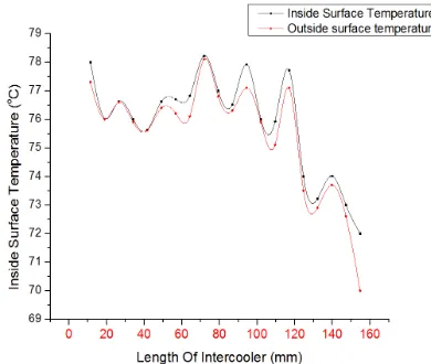
The following figure shows the variation of outside and inside surface temperature along the length of intercooler. The difference between temperature at each section of intercooler is small as the thickness of tube material is only 3.5 mm and the thermal conductivity of tube material is considerably high.
Fig.2.Inside,Outside Surface Temperature of Intercooler vs Length of Intercooler
6.2 Temperature distribution over the fins
The following figure shows the variation of temperature over each fin with respect to its base temperature.
The temperature distribution is calculated by using the modified Bessel’s function.
6.3 Variation of heat transfer rate along the length of intercooler :
[image:7.612.41.236.193.358.2]The following figure shows the variation of heat transfer rate along the intercooler. The heat transfer rate is more at the section where the fins are present. Heat transfer rate is also The following figure shows the variation of outside and inside surface temperature along the length of intercooler. The difference between temperature at each section of intercooler is small as the thickness of tube material is only l conductivity of tube material is
Fig.2.Inside,Outside Surface Temperature of Intercooler vs
The following figure shows the variation of temperature over
The temperature distribution is calculated by using the
6.3 Variation of heat transfer rate along the length of
The following figure shows the variation of heat transfer rate along the intercooler. The heat transfer rate is more at the section where the fins are present. Heat transfer rate is also
depends on the difference between the local surface temperature and the ambient temperature.
Fig 3. Rate of Heat Transfer vs Length of Intercooler
6.4 Modelling of 2-D geometry of Intercooler Using ANSYS
1. Fin type:
[image:7.612.324.497.406.549.2]Circular fins of Rectangular cross section The following figures shows the directi temperature distribution on the fins
Fig. 4. Temperature distribution on the intercooler (rectangular profile)
Heat transfer rate is calculated from the
2. Fin type :
Circular fins of Triangular cross section
The following figures show the temperature distribution for circular fins of triangular profile. Triangular fins are generally adopted as the heat transfer is more when compared to the rectangular fins. To know the heat transf
depends on the difference between the local surface he ambient temperature.
Fig 3. Rate of Heat Transfer vs Length of Intercooler
D geometry of Intercooler
Circular fins of Rectangular cross section
The following figures shows the direction of heat flow and the
Fig. 4. Temperature distribution on the intercooler
Heat transfer rate is calculated from the ANSYS is 89.773 W
of Triangular cross section
the same conditions as that of the circular fins of rectangular profile.
Fig.5.Temperature distribution on the intercooler (triangular profile)
The total heat transfer rate calculated from the ANSYS for this case is 92.82 W.
7. CONCLUSIONS:
The compression is approximated to be isentropic which is evident from the temperature of exit air (from the first stage of compression)
Heat flow for annular fins of triangular profile from the analysis using ANSYS is obtained as 92.82 W which is more than the heat flow for annular fins of rectangular profile which is obtained as 89.773 W.
Fins of triangular profile are suggested because for equivalent heat transfer it requires much less volume (fin material) than rectangular profile.
But, in view of their larger manufacturing costs, annular fin of rectangular profile is commonly used , which is justified as the heat flow is only 3.39% more in case of triangular fins. Temperature distribution for fins which is in the form of modified Bessel’s equation is obtained for all the fins and calculated tip temperatures are approaching the experimentally measured tip temperatures and tip temperatures which are obtained from ANSYS.
Total heat flow obtained from the theoretical analysis is 89.44 W, while that from the analysis using ANSYS is 89.77W.The percentage deviation between theoretical analysis and using ANSYS is 0.003 %.
8.REFERENCES
[1] Parametric performance of gas turbine power
plant with effect intercooler by Wadhah Hussein Abdul Razzaq Al- Doori - Vol. 5, Modern Applied Science,June 2011.
[2] Fin Efficiency of an Annular Fin Composed of a Substrate Metallic Fin and a Coating Layer by Ping Tu Hideo Inaba, Akihiko Horibe, Zhongmin Li, Naoto Haruki - Vol. 128, Transactions of the ASME -2006
[3] Maximizing heat transfer through joint fin systems by A.-R. A. Khaled - Vol. 128, Transactions of the ASME (Feb 2006)
[4] Full analysis of low finned tube heat exchangers by M. R. Jafari Nasr and A. T. Zoghi - Vol. 16,
IJE Transactions A: Basics (Sep- 2003)
[5]Efficiency of extended surfaces with simultaneous heat and mass transfer by Elmahdy, A. H.; Biggs, 1A, pp.135-143, R. C. ASHRAE Transactions
[6] Fin efficiency calculation in enhanced fin-and-tube heat exchangers in dry conditions by Thomas Perrotin Denis Clodic, International Congress of Refrigeration (2003)
[7]Numerical and experimental analysis on Heat transfer and fluid flow in 3-D circular finned –tube Heat exchangers by J.Y.Jang and J.T Lai, International conference on CFD in Mineral & Metal Processing and Power Generation (CSIRO1997)