Technology (IJRASET)
Effect of change of substrate on I shape patch
antenna using slots and stub for wireless
applications
Vishal Kalara1, Ruchika Manchanda2 1
Scholar (M.Tech, ECE) GNIT ,Mullana, Ambala, 2Assistant Prof., ECE Department GNIT ,Mullana, Ambala
Abstract- in this paper an rectangular patch whose top corner has been cut and I shape slot, L shape slot along with stub is introduced. The substrate Duroide is used for the designed antenna with dielectric constant 2.2 and thickness of 1.6mm. The overall dimension of the antenna is 18.9×26×1.6mm3.This antenna is fed by a microstrip feeding line. In this paper the effects of different antenna parameters like gain, return loss, VSWR and radiation pattern has been discussed. The antenna is designed using HFSS13.0 software. The VSWR obtained for all the designed antenna is less than 2.
Keywords- microstrip patch antenna, parasitic stubs, slot antenna, multiband.
I. INTRODUCTION
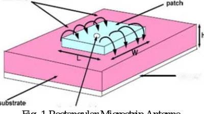
[image:2.612.207.407.422.534.2]Wireless communication industry has seen incredible advancements in last decade. Frequency allocation spectrum is getting dense day by day with the amount of research going on in recent times. Printed microstrip antennas have been very popular because they can be easily integrated in complex circuitries [1]. A microstrip patch antenna is used to process ultra high frequency signals. Microstrip patch antenna is a wideband, narrow beam, occupy less space antenna placed over an insulating material such as FR4, glass, ceramic etc whose dielectric constant lies between 2.2≤ εr≤12 The microstrip antenna mainly consist of Ground , Substrate , patch and feed line. The base of the antenna is known as ground plane. Just above the ground with the same dimension a substrate is placed.
Fig. 1 Rectangular Microstrip Antenna
The patch in the antenna is made of a conducting material CU (copper) or Au (gold) Microstrip antennas are widely used in several applications where reduced size, weight and cost, high performance and easily fabricated and installed antennas are required such as airborne, space borne commercial and military applications and mobile and wireless technologies. Microstrip patch can be of different shapes such as rectangular, square or disk patches. They can provide linear, dual or circular polarization by appropriate feeding [4]. Because of the fast growing demand in wireless communication, mobile communication, radar applications and any other application coplanar waveguide fed antennas have invited much interest due to light weight, low profile, small size, and ease of fabrication [12]. Dual-band microstrip antennas (MSA) are realized by using techniques such as stub loading, cutting a resonant slot inside the patch, or by placing a shorting post at an appropriate position inside the patch [1-15]. When placed on the radiating edges of a rectangular microstrip antenna (RMSA), an open-circuit quarter wavelength stub or a short-circuit half-wavelength stub offers capacitive or inductive impedance around the resonance frequency of the rectangular microstrip antenna. Dual-band characteristics are thereby realized for the antenna [8].
Technology (IJRASET)
5880 are two different substrates that are used mostly in microstrip antenna design. FR-4 substrate has dielectric constant of 4.4 and loss tangent of 0.02 whereas Duroide (tm) has dielectric constant of 2.2 and loss tangent of 0.0009. In proposed design FR-4 has been used as substrate because it reduces size of antenna and has good efficiency and bandwidth.
II. ANTENNA DESIGN AND IMPLEMENTATION
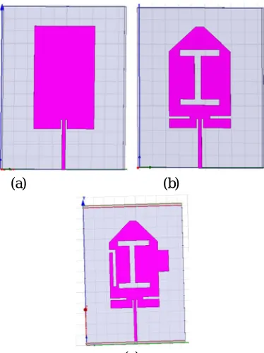
An edge tapered I shape microstrip patch antenna with slits on the patch has been designed. I shape microstrip patch antenna has been designed by taking a rectangular patch of 9.3×16 mm2. Upper corner of the patch has been cut , parasitic stub and I shape slot is inserted on the patch as shown in the figure 3.1. The effect of change of height of substrate has been studied. All the simulations has been simulated in HFSS software. The configuration of the antenna are having FR4 substrate with relative permittivity €sub=4.4
and thickness t=1.6mm having dimensions L× W=18.9 mm×26mm. The 50Ω CPW feed line is designed to have a center conductor
with of s=8mm and a gap with of .5 mm. The antenna has been designed by using transmission line model which is most accurate method.
(a) (b)
(c)
Fig 2: fig(a) 2D view of simple patch, fig(b) edge tapered with slot and I shape antenna and fig(c) I shape by adding stub. TABLE 1
DESIGN PARAMETER AND CORRESPONDING VALUES
Subject Dimensions
Ground Size 18.9×26 mm
Patch Size 9.3×16.4 mm
Loss Tangent .02
Feed line size 8×.5 mm
Substrate Used FR4
Thickness 1.6 mm
Feed line Technique Microstrip line feed.
[image:3.612.213.400.233.483.2]Technology (IJRASET)
A. Return loss
[image:4.612.204.420.103.227.2]For better antenna performance return loss of antenna should be more negative the value that we will consider is below -10 dB.
[image:4.612.47.509.296.694.2]Fig 3: input reflection coefficient of I shape with parasitic stub using one slit rectangular patch antenna for FR4 and Duroide substrate
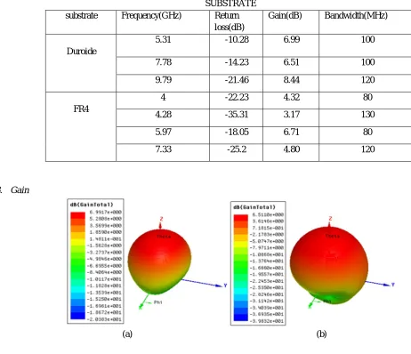
TABLE 2
SIMULATED RESULTS OF I SHAPE PARASITIC STUB WITH ONE SLIT PATCH ANTENNA USING DUROIDE AND FR4 SUBSTRATE
substrate Frequency(GHz) Return
loss(dB)
Gain(dB) Bandwidth(MHz)
Duroide
5.31 -10.28 6.99 100
7.78 -14.23 6.51 100
9.79 -21.46 8.44 120
FR4
4 -22.23 4.32 80
4.28 -35.31 3.17 130
5.97 -18.05 6.71 80
7.33 -25.2 4.80 120
B. Gain
Technology (IJRASET)
[image:5.612.165.452.261.531.2](c)
Fig 4: Gain of I shape with parasitic stub using one slit rectangular patch antenna fig(a)5.31GHz fig(b)7.78GHz fig(c)9.79GHz
Radiation pattern
(a) (b)
(c)
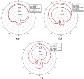
Fig 5: Radiation pattern of I shape with parasitic stub using one slit rectangular patch antenna using Duroide substrate fig (a) for f=5.31 GHz fig (b) f=7.78 GHz fig(c) f=9.79 GHz
C. VSWR
VSWR obtained for the I shape using stub and one slit rectangular patch antenna is 1 at all three resonant frequencies.
[image:5.612.200.418.603.700.2]Technology (IJRASET)
III. RESULTS AND DISCUSSION
From table 2 it has been concluded that when Duroide issued as a substrate antenna will resonate at 3 frequencies whereas for FR4 substrate antenna will resonate at four frequencies. When return losses are compared for Duroide antenna has return losses of -10.28dB,-14,23 dB and -21.46 dB and for FR4 substrate return losses obtained are-22.23,-35.31,-18.05 and -25.2 dB. The gain and bandwidth obtained for Duroide substrate is more than the Fr4 substrate. From figure 2 it is concluded than for Duroide substrate resonance frequencies of antenna get shifted towards right side that is toward 10 GHz.
IV. CONCLUSIONS
In this paper antenna with I slot ,L slot on patch and also the top corner of the patch has been cut by adding a stub in the right side of the patch.By inserting slot and cutting the edges the size of the antenna get reduced. Effect of using substrate is shown in this paper as FR4 and Duroide both are the most commonly used substrate material. Fr4 is used because it is cheap and easily available in the market having 4 as relative dielectric constant.When Duroide is used as substrate then after fabrication you get rough surface
between patch and substrate.The total size of the antenna is 18.9×26×1.6mm3.The proposed antenna shows an average gain of 7.31
dB which is better than FR4 substrate which is4.75 dB. The proposed antenna finds application in wireless local area network (WLAN), worldwide interoperability for microwave access (WIMAX), RADAR and satellite.
REFRENCES
[1] R.K. sharan,S.K. Sharma,A .Gupta,R.K Chaoudhary “An Edge Tapered Rectangular Patch Antenna with Parasitic Stubs and Slot for Wideband Applications” Wireless Pers Commun Vol 86,2016, pp 1213–1220.
[2] I.Zahraoui, J,Zabitou andL. EI Abdellaoui “A CPW-Fed Multiband Planar Antenna For Mobile Phone Applications”RFID and adaptive wireless sensornetworks(RAWSN), 2015 pp-48-51.
[3] N.Bayatmaku,p.Lotfi and M.Azarmanesh “Design Of Simple Multiband Patch AntennaFor Mobile Communication Applications Using New E-Shape Fractal”IEEE Antennas And Wireless Propagation Letters, Vol. 10, 2011 Pp-873-875
[4] K.Sankar,R.Bargavi, and S.Arivumani Samson “Single Layer Dual band G-shaped patch antenna” International Conference on Communication and Signal Processing, 2014, pp-636-639.
[5] R. Ghatak, S. Chatterjee and D.R. Poddar “Wideband fractal shaped slot antenna for X-band application” Electronics Letters Vol. 48, 2012.
[6] A. Yadav, B.Chauhan, A. Jain “Microstrip Symmetrical E-Shape Patch Antenna for the Wireless Communication Systems” International Journal of Emerging Technology and Advanced Engineering Volume 2, Issue 12, 2012,pp 241-244.
[7] Balanis, C. A. (2005). Antenna theory: Analysis and design. Hoboken: Wiley.
[8] A.A. Deshmukh1 and K. P. Rav “Multi-Band Configurations of Stub-Loaded Slotted Rectangular Microstrip Antennas”IEEE Antennas and Propagation Magazine, Vol. 52, No.1, February 2010 pp 89-103.
[9] S. E Jasim, M. A. Jusoh, M. H. Mazwir and S. N. S. Mahmud “Finding The Best Feeding Point Location Of Patch Antenna Using HFSS” ARPN Journal of Engineering and Applied Sciences VOL. 10, NO. 23, December 2015 pp17444-17449.
[10] R. Zaker, C. Ghobadi, and J. Nourinia “Novel Modified UWB Planar Monopole Antenna With Variable Frequency Band-Notch Function” IEEE Antennas And Wireless Propagation Letters, Vol. 7, 2008 ,Pp-112-114.
[11] Y. Chen, S. Yang, and Zaiping Nie “Bandwidth Enhancement Method for Low Profile E-Shaped Microstrip Patch Antennas” Ieee Transactions On Antennas And Propagation, Vol. 58, No. 7, July 2010 Pp2442-2447
[12] A. George R. Nakkeeran “Conductor Backed CPW Fed Antenna for 2.4 GHz WLAN Applications” International Conference on Green Computing, Communication and Conservation of Energy (ICGCE)2013, pp112-115