5
II
February 2017
Technology (IJRASET)
Design and Implementation of Three Way
Transportation
Arun. R1, Anandu Surendran2, V. Guhan3, S. Inbakumar4, Karthikryan. R5
1, 2, 3, 4, 5, Department of mechatronics Anna University, Nehru Institute of Engineering And Technology Coimbatore, Tamil Nadu,
Abstract: introducing a new design a vehicle by comparing the data and specifications of present vehicle in category and to calculate the performance characteristics and possibilities. For that the vehicle is conceptually designed by using software’s and finally to create a prototype model by using the RC’s and lightweight materials. Also this proposed system can be used for defense and many intelligence applications. Also necessary diagrams, graphs and calculations are included wherever needed. Keywords: rotor, lift, aerodynamic, air, water,
I. INTRODUCTION
In the present scenario the need of transportation increases in all fields. The development of a nation depends upon the variety of transports like Airways, waterways and roadways. The vehicles available for Airways are Airplanes and helicopters, for roadways cars, trucks etc. and for waterways ships and submarines. Engineers are trying to improve the technologies in all the three modes of transportation. This project concentrates on integrating all the three modes. By considering all the aspects the vehicle is designed.
II. LITERATURE SURVEY
joseph n.ayoola: from california, patent name: air land and sea vehicle, u.s pat no: 4579297, dated april 1, 1986: designed a vehicle which is convertible between aircraft form, road vehicle form and boat form. the conversion between the three are by manual and also by retractable.leo smith: from new york, patent name: vertical take-off and landing vehicle for land water and air transport, u.s pat no: 6517026b1, dated feb 11, 2003: the invention related to a vehicle for land, air and water, more specifically by vertical take-off and landing principle. for land transport the methodology was by four wheel drive as like as present automobiles. for water and air transport inventor utilizes compressed air to lift and propel the vehicle. charles g.bixel: from walton beach (u.s), patent name: hovercraft ground-effect vehicle, u.s pat no: 5105898, dated april 21, 1992: the proposed concept of the inventor was to design a flying hovercraft which can be capable of moving on air, water and land. it has a highly elongated flat wing and need separate runway for take-off and landing.anthony caruso: from enfield ,ct(u.s), patent name: light weight vehicle operable on air water and in the air, u.s pat no:0247819a1,dated nov 10,2005:designed a light weight vehicle consists of a two power driven mountain bike wheels, a large propeller used to propel the vehicle in air and water, additionally a parachute was employed during flying.
III. PROPOSED SYSTEM
By considering all the drawbacks and imparting innovative ideas the AWL vehicle is proposed. The concept vehicle should satisfy the need in Airways, Roadways and waterways. For this the structure is designed to suit all the conditions. The vehicle must have a gross weight between 1000-2000 kilogram. For the land and water operations the technologies used in earlier designs is preferred as in Aquada. Hence the road ability and floating can been achieved. While concentrating to lift the vehicle during air operation the technologies applied on verticopter can be altered and studied to achieve the suitable design. The final vehicle design will support the vertical take-off and landing over land and water. For designing this vehicle the methodology as stated in design process is followed and related calculations are made. Also by using the design software’s the design concept will be created. According to that designed concept a practical model can be created. The scale down RC model will be practically created with the facilities available and tested. If the vehicle is successful then the actual vehicle can be made according to its ratios. For the proposed model the key parameters and technology used are explained in this project. The materials used for manufacturing are advanced light weight material. It should support the vehicle in all the operating conditions thus designed vehicle will solve the transportation needs in all the three modes the name is selected as
A. Selection of rotor
The proposed vehicle was designed with the use of coaxial rotor for vertical take-off and landing. Its has been implemented in
Technology (IJRASET)
reactive moment compensation fundamentally different from that of the single rotor configuration. To compensate for the reactive moment of the single-rotor helicopter's main rotor, there should be developed the tail rotor's side force applied to the airframe, while the coaxial-rotor helicopter has its rotors' reactive moments compensating each other directly in their axis of rotation. This removes the need for any additional forces. Rotors' reactive moments are compensated automatically throughout the flight, thus requiring no
interference on the part of the pilot.A peculiarity of the coaxial rotor featuring zero reactive moment in the balanced flight is the
fact that the pilot's operating the pedals creates disparity between the upper and lower engines' reactive moments with the resulting summary reactive moment being used as the direction control capability. The reactive moment compensation method employed in the single-rotor helicopter requires the pilot's constant attention to adjusting the tail rotor's side force to maintain the helicopter's balance throughout the flight, thus putting the helicopter to certain disadvantage. As far as power is concerned, the coaxial helicopter has a considerable edge over its single-rotor counterpart, since all free power is transferred to the rotor drive, i.e. used for developing the lift, while the single-rotor helicopter's tail rotor power consumption accounts for 10-12% of total power. Another important feature of the coaxial configuration is revealed when the helicopter is hovering. The upper rotor race grows considerably more narrow in the lower rotor plane, which allows the lower rotor to suck in additional air thus increasing the rotor race cross-section and reduces the power used for developing the lift. The contra-rotation of coaxial rotors as shown in fig.2 leads to significant reduction in power, which is required for swirling the jet. Flight-testing as well as other experimental data shows the coaxial rotors to be 6-10% more efficient as compared to the single-rotor helicopter.
Fig.1. Coaxial Rotor- Counter Rotation
Graph.1.Coaxial rotors and single rotor aerodynamic quality in the hover
Technology (IJRASET)
substantial advantage in the hover ceiling (by 500-1,000 m) and vertical rate of climb (by 4-5 m/sec). Despite the fact that the twin-rotor system mast creates greater drag for the coaxial helicopter as compared to its single-twin-rotor opposite number, the flight testing of coaxial-rotor and single-rotor helicopters of the same type displayed no obvious increase in drag, which is owing to the following reasons: 1.beneficial mutual effect of coaxial rotors in forward flight; it appears as the biplane cell effect and ensures substantial reduction in power that is developed by the engine for creating the lift; 2.lack of the tail rotor and need for powering it; 3.lack of the tail rotor drag and negative interference of the tail rotor and the tail boom; measures taken in designing the coaxial-rotor helicopter (Ka-50) with lesser drag (i.e. by retracting the landing gear in flight).
The coaxial configuration allows the helicopter, while being smaller and lighter than the single-rotor one, to feature important tactical advantage. To assess the changes in the dimension and weight of single-rotor and coaxial-rotor helicopters, it makes sense to compare the following cases:coaxial-rotor and single-rotor helicopters have the same airborne weight and available power developed by their engines (Ka-50 and Mi-28);2coaxial-rotor and single-rotor helicopters have the rotor blades of the same diameter (Ka-50andAH-64). In the first instance the coaxial configuration results in reducing the coaxial-rotor helicopter size by 35-40% as compared with the single-rotor one. This is mainly due to the reduction in the rotor's diameter thanks to greater fineness in the hover, lack of power loss for the lack of the tail rotor and the need for mounting it on the rear part of the airframe - outside the main rotor's blade-swept area. In the second instance, featuring lesser fineness and additional power loss in driving the tail rotor, the single-rotor helicopter has a lesser available flight weight. In this case, the presence of the tail rotor leads to the helicopter's dimension being 20% more than that of the coaxial one. Concentration of the whole control system in the coaxial rotor and the availability of the coaxial rotor directional control capability through the disparity in moments provides coaxial-rotor helicopters with another important feature - the control system becomes nearly independent of the angle of slide. It is this and the lack of the tail rotor that provides limitless opportunities for performing flat manoeuvres at high angles of slide. The coaxial-rotor helicopter's empennage places no restrictions on the value of the angle of slide since it is expected to deal with the changing of the angle of slide within 180 degrees. A radically new manoeuvre - 'flat' turn - has been tested through the use of the Ka-50 and accepted for use. At speed of up to 90-100 km/h this manoeuvre could be performed at 180 degrees both left and right in the horizontal plane while at a speed of up to 230 km/h it is performed within 90 degrees as shown in graph in both directions with the banking being close to zero.
B. Structure design
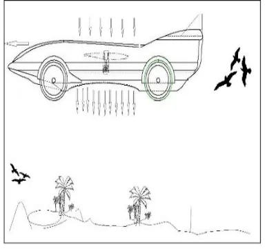
[image:4.612.200.404.466.694.2]The primary structure is based on a car. The hull of a boat is integrated to obtain the floatable condition. The coaxial rotor mechanism is attached to the chassis which forms the basis for the air mode
Fig 2 .Isometric view of designed vehicle
Technology (IJRASET)
Fig.4. front view
Fig.5. Body of Designed Vehicle (Right side view)
Fig.6 .Body of Designed Vehicle (Isometric view)
C. Working
The hull has a keel fin that gives directional stability. Spray rails and chine’s contain the spray either side of the amphibian and away from the cockpit. In addition Chines and Strakes provide grip in cornering to give exceptional manoeuvrability.
Advantages:
Managing the spray ensures that the occupants remain dry.
The hull has been carefully, hydro-dynamically engineered to ensure maximum manoeuvrability on water in displacement and planing modes.
Designed to be aerodynamic in road mode and hydrodynamic in marine mode Composite construction, single piece mould.
Provides over 1750kg of hydrodynamic lift.
D. Selection of water jet
Technology (IJRASET)
Fig.08.Figure Showing the Waterjet Transmission from Engine
Water enters the jet from beneath the amphibian via the jet intake. A flush mounted stone guard prevents large objects from entering. The engine driven rotating impeller accelerates the flow, this imparts axial and centrifugal energy to the water stream. The stator blades & nozzle then straightens and converges the flow producing a high-speed jet. This is used to propel the amphibian. The steering nozzle is mounted on the back of the stator nozzle and is connected to the normal steering wheel. It is used to direct the water jet in order to steer the amphibian. The Water Jet may be run in reverse to provide the amphibian with a low speed reversing capability.
E. Power transmission
[image:6.612.204.404.406.616.2]The power plant used for this vehicle needs a master gearbox to control the power given for various systems or outputs. For the waterjet drive and rotor one gearbox with transfercase is used. And in land another engine is coupled with a gearbox provided for wheels. As rotor needs high power both engines are combined. And other to cases is used with one of the two.
Fig. 9. Layout of power transmission of designed AWL vehicle
A transfer case is a part of a four wheel drive system found in four wheel drive and all-wheel drive vehicles. The transfer case is connected to the transmission and also to the front and rear axles by means of drive shafts. Instead of front wheel drive it is diverted
to water jet transmission.The transfer case receives power from the transmission and sends it to both the water jet and rear axles.
Technology (IJRASET)
[image:7.612.188.413.90.426.2]F. Layout of vehicle
Fig.10. Pictorial view of AWL vehicle on air
Fig. 11. .Pictorial view of AWL vehicle in water
IV. APPLICATIONS The main application of this AWL is in the field of
Civilian Military Air Surveillance
For emergency situations in case of floods, earth quake, etc., In rescuing operations.
Can be used as a unique mode of transportation all over the world.
V. CONCLUSION AND FUTURE SCOPE
The proposed concept design for the AWL vehicle had numerous studies to arrive the final design. Initially for land and water mode there was a suitable solution available, which is mentioned as ‘Aquada’ an amphibian car mentioned in literature survey. Since the Air propulsion is the main task for the team. Many ideas are selected like STOL, VTOL, attaching of wings etc., by doing the survey finally helicopter based rotor system is selected and the power plants are selected as per the weight estimation. The parallel work of designing the concept in software was carried out and a scale model is developed and tested. By using coaxial rotor there was a convincing solution since it gains high thrust and does not needs anti-torque systems. As a result a model is designed and the solutions are arrived as per the expectation at the beginning. Continuous changes are necessary to make this dream project to be a reality and the vehicle will be a “REVOLUTIONARY VEHICLE” in the future.
REFERENCES
[1] Joseph N.Ayoola: From California, Patent Name: AIR LAND AND SEA VEHICLE, U.S pat no: 4579297, dated April 1, 1986
[image:7.612.210.402.98.280.2]Technology (IJRASET)
6517026B1, dated Feb 11, 2003
[3] Charles G.Bixel: From Walton Beach (U.S), Patent Name: HOVERCRAFT GROUND-EFFECT VEHICLE, U.S pat no: 5105898, dated April 21, 1992: [4] Anthony Caruso: From Enfield ,CT(U.S), Patent Name: LIGHT WEIGHT VEHICLE OPERABLE ON AIR WATER AND IN THE AIR, U.S pat