International Journal of Emerging Technology and Advanced Engineering
Website: www.ijetae.com (ISSN 2250-2459, ISO 9001:2008 Certified Journal, Volume 7, Issue 8, August 2017)
94
―ECM Tool Performance Improvement by Pro-E software‖
A. Modi
1, Pankaj Kumar Manua
2, Sukhlal Mujalda
31
Assistant Professor, 2Research Scholar, 3Assistant Workshop Supdt. Shri G.S. Institute of Technology & Science, 23 Park Road, Indore, M.P. India
Abstract— ECM process performance depends up on tool
design and optimum parameters setting. The tool design complex parameters are decided by specifications of work piece to be machined. The tool design is done with the criteria to prevent overheating and rapid corrosion to get maximum MRR. Minimum cross section is preferred for current carrying parts of the ECM tool. Different experiments are performed on an ECM machine available in an educational institution. The change in MRR with insulated tool are determined and compared with non-insulated tool results. The tool which is supplied by manufacturer is modified by design of an insulation cap with the help of Pro-E software. It resulted in-to improved MRR, better flow of electrolyte and sharp interior edges. The tool performed better with less flow rate of electrolyte also and with less overcut.
Keywords— Pro-E, ECM Tool Design, Electrolyte Flow Rate, Material Removal Rate (MRR).
I. INTRODUCTION
Electrochemical machining is non-traditional manufacturing process that can make complex stress free shapes on the surface of the costly hard and difficult conductive material. It is an electrolytic process and true shape of tool can be made by controlled dissolution. ECM applications have been now extended to electrochemical drilling, grinding, de-burring and polishing. ECM has more advantages over other machining processes such as no tool wear, absence of burr, high material removal, smooth surface finish and the ability to machine complex shapes in materials regardless of their hardness. ECM is a process in which tool moves with a certain feed rate (mm3/min) towards the work piece and its negative mirror shape reproduced on the work piece.
Masuzawa and Tanshoff [2] discussed about the 3D Model micro machining by ECM tool and its parameters. Neelam K. applies it to difficult appliance with high strength, heat-resistant material into complex shapes by conservative techniques, but such materials can be effectively machined by electrochemical machining (ECM) method. Corbett et al. suggested that the electrochemical machining are used in industry purpose due to various advantageous, such as there no tool wear, smooth surface and stress free and also complex shape in electrically conductive materials.
Sen and Shan [3] has reported that electrochemical machining processes provide a viable alternative for drilling macro- and micro-holes with exceptionally smooth surface and reasonably acceptable taper in numerous industrial applications particularly in aerospace, electronics, computer and micro-mechanics industries.
Hotoiu et al. this study about the Pulsed electrochemical micromachining (PECMM) is a metal shaping process that exploits the double layer’s capacitive effect to confine the machining reaction. Sen and Shan has reported that ECM provide a viable alternative for drilling macro- and micro-holes with exceptionally smooth surface and reasonably acceptable taper in numerous industrial applications particularly in electronics, computer and micro-mechanics industries. The experiment work is helps us to investigate the tool performance and its performance improvement and material removal rate.
Pro/Engineer is a parametric, integrated 3D solution created as suite of applications with parametric, feature-based, associative solid modeling. Usman et. al. Discussed that the major commercial CAD/CAM systems, such as Uni-graphics, Pro/E, IDEAS, CATIA, etc. have many specialized modules packed together and running on their own proprietary databases. It reduces product development cycles, faster time to market and greatly enhance the competitiveness of any enterprises that fully adapt the techniques. PTC considers that with Pro/ENGINEER, we have the power to go extra mile in quality, design and speed. Fan et. al. Uses Pro/ENGINEER for development of die sets standard parts library, to improve die design. S.B. Ahmad introduces the tool of Pro-E which is finally used to design and modeling the objects.
International Journal of Emerging Technology and Advanced Engineering
Website: www.ijetae.com (ISSN 2250-2459, ISO 9001:2008 Certified Journal, Volume 7, Issue 8, August 2017)
[image:2.612.54.281.131.262.2]95
Figure -1. Working principle of Electrochemical Machining (1)
In the electrochemical machining the metal of the work piece is removed and the work piece is connected to the positive and the tool is connected to the negative. When current is passed, the dissolution of anode occurs.
II. EXPERIMENT SETUP
Different experiments are performed on ECM machine with varying tools and other parameters. ECM process parameters which affect MRR are current, voltage, electrolyte type, pressure, flow and concentrations etc. However the dissolution rate is more when the gap is less and vice versa the current density is inversely proportional to the gap. During experiments the gap is uniform and thus the shape of the tool is reproduce in the job.
Figure-2 Experiment set-up of ECM
ECM consists of three main subsystems: Machining Cell, Control Panel, Electrolyte Circulation system. In ECM, servo motorized vertical up/down movement of the tool is provided and power supply is a perfect integration of, high current electrical, power electronics and precision programmable microcontroller based technologies.
The electrolyte is pumped from a tank, lined by corrosion resistant coating with the help of corrosion resistant pump & is fed to the job.
[image:2.612.329.560.362.522.2]Moarrefzadeh A., suggest that both the electrolyte and the metal sludge are then recycled [2]. According to Rajurkr. K.P., ECM is a major process for semiconductor devices and thin metallic films [4]. Bhattacharyya et.al, discussed that how ECM processes were also adopted in the aerospace and electronics industries for shaping and finishing operations of a variety of parts that are a few microns in diameter [6]. A relationship is presented by Muttamara et. al, between ECM parameter and groove depth and groove ratio [7]. The electrolyte is circulated often through the cathode to wash out the metal hydroxide sludge and to ventilate the hydrogen formed in the course of electrolysis [8]. Table-1 indicates the machine technical specifications as-
TABLE-1
ECM TECHNICAL SPECIFICATIONS
S.N. Particulars Parameters
1. Current Rating 0-300 A. DC at voltage 0 - 20 V.
2. Efficiency 80% at partial & full load condition
3. Protections Over load, Short circuit, single phasing
4. Operation Modes Manual/Automatic
5. Timer 0 - 99.9 min
6. Tool Feed 0.2 to 2 mm / min.
7. Z Axis Tool-Control
Forward, reverse, auto forward /reverse, through controller
8. Supply 415 +/- 10%, 3ϕ AC, 50 Hz
Different researcher consider feed rate between tool and work-piece as most influential parameter for higher MRR. The surface finish and tolerance control are other important parameter and factor which influences tool design. Low electrolyte concentration is useful to decrease the machining gap and increased current leads to electrolyte heating [8].
III. ECMTOOL DESIGN CONSIDERATION
Designing the tool and insulation of the tool includes an exhaustive review of literature and various designing consideration for determining the all factors which effect the designing process and also design the tool surface which can improve the surface finish of the work piece. Machining Cell
Electrolyte circulation
[image:2.612.48.289.459.620.2]International Journal of Emerging Technology and Advanced Engineering
Website: www.ijetae.com (ISSN 2250-2459, ISO 9001:2008 Certified Journal, Volume 7, Issue 8, August 2017)
96
The machine tool is rigidly constructed to prevent vibration and consequent inaccuracies [8]. Minimum cross section is preferred for current carrying parts of the ECM tool. To reduce overcut and side taper tool insulation is also suggested [10]. Figure-3 indicates the different shapes of tools supplied with ECM.The electro-chemical machine and tool is designed to consider process most influential parameter as feed rate and other parameters like current, electrolyte and voltage are set to get best performance from machine. The feed rate and electrolyte temperature is also maintained constant during the process to get maximum MRR with different tools. The ECM machine works in both auto-manual modes.
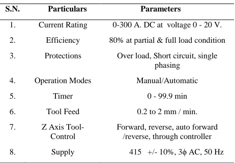
Figure-3 Different tools used for ECM machine (9)
The properties expected from the tool material are- Electrical and thermal conductivity-High
Stiffness-High Easy machinability. Corrosion resistance- High
Generally, aluminum, copper, brass, titanium, cupro-nickel and stainless steel are used as tool materials. Tool design requires careful consideration to maintain a constant gap over the entire work piece surface [8]. Also the flow characteristics of the electrolyte need to be considered during the tool design, the modification of the tool profile to get the required final surface is relatively complex. It is generally done using empirical methods. Alternatively, the modern complex analysis methods such as finite element can also be used to get the final tool design [7].
Different tool profiles are designed to allow the flow of electrolyte properly in the gap of the work to cut in desired the profile with desired dimension. Dolbier et al. [5] suggested about the insulation of the tool with a very thin insulation layer. Insulated tool can improve the machining rate of the job and also insulated tool performance is better as compare to the un-insulated tool.
To reduce coating thickness, additional operation of etching is required. A polymer like parylene has been used for conformal coatings in a wide variety of applications. Insulated tool electrodes have many advantages. The machining depth can be increased because there is no size effect according to the machining depth, as shown in Figure-4.
Figure-4 Schematic diagram of side effect (a) un-insulated tool, (b)
insulated tool [7]
IV. EXPERIMENTAL WORK ON ECM
Different experiments are performed to determine MRR of ECM with different tools and different settings. Table-2 indicates the experimental settings
details-TABLE-2
Experimental Setting Details
Voltage 0-20V
Current 0-300A
Current density 0-25A/cm2 Inter electrode gap 0-0.5mm Feed rate range(mm/min) 0-0.86
Power supply DC Continuous Electrolyte flow rate 0-10 LPM Electrolyte type NaNO3 Electrolyte Concentration 200g/l
Tool material Copper
Number of Tool Used 4
Electrolyte temperature 20-30 °C
Work Piece Aluminum
Machining Time 15-20min
Experiment is done by changing the flow set of electrolyte (%). The tool used of copper material and electrolyte is Sodium nitrate. The different tools performance is determined with aluminum plate as work material.
International Journal of Emerging Technology and Advanced Engineering
Website: www.ijetae.com (ISSN 2250-2459, ISO 9001:2008 Certified Journal, Volume 7, Issue 8, August 2017)
97
[image:4.612.317.555.120.352.2]Figure -5 Different Machining layout of the different tool.
TABLE-3
MRR and experiment data with different tools.
Ex.
No.
Pressure
(bar)
Flow
Rate
(lpm)
Final
Weight
(g)
Time
(sec)
Material
Removal Rate
(mm3/min)
1 0.23 2.72 104.52 900 0.003644
2 0.25 2.80 104.43 900 0.003744
3 0.28 2.89 104.32 900 0.003866
4 0.31 2.98 105.82 500 0.003944
Material removal rate is a function of feed rate which dictates the current passed between the work and the tool. The high feed rate not only is productive but also produces best quality of surface finish. Metal removal rate becomes poor with low voltage, low electrolyte concentration and low temperature. The MRR are determined as-.
Initial Weight – Final Weight
MRR = ____________________________________ 𝑚𝑚3/min Time
The manufacturer of ECM specified to use machine at flow rate more than 50% for optimum performance.
To determine the individual tool performance, numbers of experiments are performed by using a same tool but changing the flow rate of electrolyte, and its feed rate. The Voltage is 15V and Machining time set of 1200sec, feed rate is 0.21mm/min and material weight of 104.8gram.Figure-6 indicates the profile obtained by the different experiments and table-4 its MRR as calculated.
[image:4.612.51.285.356.484.2]Figure-6 Different layout of same tool
Table-4
MRR and experiment data with different parameters and same tool
Ex. No.
Pressure (bar)
Flow Rate (lpm)
Final Weight
(g)
Flow Set (%)
Material Removal Rate (mm3/min)
1 0.09 2.23 102.97 50 0.001525
2 0.12 2.40 102.32 70 0.002066
3 0.23 2.98 101.56 90 0.002700
4 0.29 3.08 101.15 92 0.003041
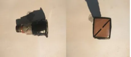
[image:4.612.319.569.370.488.2]To determine influence of tool insulation on MRR and work piece profile, different experiments are performed by using insulated tool as shown in figure-7 with same setting.
Figure-7 Insulated tool as used in ECM experiments
V. RESULTS
The ECM process performance and accuracy is depend on MRR and overcut.
1
.
2
.
3
.
4
.
4
.
3
.
2
.
1
[image:4.612.330.560.536.636.2]International Journal of Emerging Technology and Advanced Engineering
Website: www.ijetae.com (ISSN 2250-2459, ISO 9001:2008 Certified Journal, Volume 7, Issue 8, August 2017)
98
In the ECM process, accuracy, surface finish and profile obtain is better if insulated tool are used. A insulated cap for current carrying tool is designed on Pro-E. In Table-5 a comparison is made for insulation and non-insulated tool. Figure-8 indicates the profile of work piece as obtained with insulated tool.Figure-8 Profile of work piece with insulated tool.
Table-5
Experiment data with insulation/ non-insulated tool.
Ex. details
Flow Rate (LPM)
Final Weight
(g)
Flow pr. (%)
Material Removal Rate (mm3/min)
Average change of material rate
Without
insulation
3.10 103.05 95 0.005277 Increased
With insulation
3.10 103.23 95 0.005077 Decreased
Without insulated tool MRR, is increased as tool all side are open for machining but spread-out from the actual size or overcut will be developed and when, the insulated tool is used than, straight cut will developed with less spread-out and the proper size of the material will be resulted. The ECM process performance is improved and no side effect like turbulence in electrolyte flow is developed. ECM process tool has no provision for insulation. To improve the electrolyte flow in flow set less than 50%, double slit is suggested in tool tip. Table-6 indicates the experiment results for insulation/ non-insulated tool.
Table-6
Experiment Results with insulation/ non-insulated tool.
S.N. Parameters Workout put
1. MRR Material removal rate (MRR) is high when flow Set of electrolyte will be increase
2. Over cut/size
variation
Over cut of job is reduced when the insulated tool is used.
3. Electrolyte
flow
Proper flow of electrolyte on the surface of the tool can improve the flow electron between the cathode and anode.
4. Profile
obtained
Better with insulated tool.
5. Surface
finish
Better surface finish obtained as visualised from machine surface.
Figure-9 Tool (a) Uu-insulated tool, (b) Insulated tool.
The insulated cap is designed with Pro-E to obtain perfact results of insulation and to get better flow with less pressure of electrolyte in the tool, the number of slit increased from one to two as shown in Figure-10.A better and smooth electrolyte flow can also obtained by proper streaming of tool tip. It will be useful to reduce the pressure drop across the gap. Reverse flow can also designed to remove the metal slug.
International Journal of Emerging Technology and Advanced Engineering
Website: www.ijetae.com (ISSN 2250-2459, ISO 9001:2008 Certified Journal, Volume 7, Issue 8, August 2017)
99
VI. CONCLUSIONSIn this work experiment have been done with different tools and parameter settings. Improvement in the MRR found with proper flow of electrolyte and less over cut of the work material. The MRR is increased by increasing the flow rate of the electrolyte, and also when insulation is provided than the over cut of material will also be reduce. The over-cut control is difficult for tool without insulation. In the present study on the effect of machining responses are MRR, SR of the aluminum specimen using a Cu electrode tool have been investigated for ECM process. The experiment was conducted under various machining parameters setting of voltage (V), feed (F) and electrolyte flow set. The graph in Figure-11 indicates the relatioship as obtained during different experiments that as the flow rate is increases the MRR is also increases.
3.1 3.0 2.9 2.8 2.7 2.6 2.5 2.4 2.3 2.2 0.00325
0.00300
0.00275
0.00250
0.00225
0.00200
0.00175
0.00150
FLOW RATE (LPM)
M
R
R
(m
m
3/
m
in
)
Scatterplot of MRR(mm3/min) vs FLOW RATE (LPM)
Figure-11 Graph MRR vs Flow Rate
REFERENCES
[1] J.A Mc Geough,(1974), Principle of Electrochemical Machining, Chapman & Hall, London,.
[2] M. Datta and D. Harris, (2013), Electro chemical micromachining: an environmentally friendly, high speed processing technology, Electrochemical Acta 42 (1997) 3007.
[3] M. Sen, H.S. (2005) Shan, A review of electrochemical macro- to micro-hole drilling processes. International Journal of Machine Tools & manufacture 45 - 137 – 152.
[4] M. Dutta, R.V. Shenoy, L.T. Romonkiw, (1996), Recent advance in the study of electro-chemical Micromachining, J. Eng. Ind. 118 (29) 29–36.
[5] B. Bhattacharyya, S. Mitra, A. K. Boro, (2002) Electro chemical machining: new possibilities for micromachining. Robotics and Computer Integrated Manufacturing 18 (2002) 283–289.
[6] P. Kumar, B. Tailor, A. Agarwal, S. S. Joshi, (2013) Evolution of electrochemical finishing processes through cross innovations and modeling, International Journal of Machine Tools & Manufacture 66 (2013)15–36
[7] John A. Schey, (2012) Introduction of manufacturing processes, McGraw Hill Education (India)
[8] P N Rao, (2015) Manufacturing Technology, Metal cutting and machine tools, Volume-2, McGraw Hill Education (India) – [9] Product manual for ECM machine supplied by META-TECH Pune -
2017.