International Journal of Emerging Technology and Advanced Engineering
Website: www.ijetae.com (ISSN 2250-2459,ISO 9001:2008 Certified Journal, Volume 4, Issue 12, December 2014)
403
Solar Tracking System using AT89C51 Microcontroller and
LDR
Soumen Ghosh
1, Nilotpal Haldar
21Asst. Professor, Department of Electronics and Instrumentation Engineering, JIS College of Engineering,
Kalyani, Pin 741235, India
2Asst. Professor, Department of Electronics and Communication Engineering, JIS College of Engineering,
Kalyani, Pin 741235, India
Abstract— This paper deals with a microcontroller based solar panel tracking system. Solar tracking enables more energy to be generated because the solar panel is always able to maintain a perpendicular profile to the sun’s rays. Development of solar panel tracking systems has been ongoing for several years now. As the sun moves across the sky during the day, it is advantageous to have the solar panels track the location of the sun, such that the panels are always perpendicular to the solar energy radiated by the sun.
Keywords— Solar system, solar panel, microcontroller AT89C51, LDR, stepper motor
I. INTRODUCTION
Renewable energy is rapidly gaining importance as an energy resource as fossil fuel prices fluctuate. The system will tend to maximize the amount of power absorbed by Photo Voltaic systems. It has been estimated that the use of a tracking system, over a fixed system, can increase the power output by 30% - 60% [9]. The increase is significant enough to make tracking a viable preposition despite of the enhancement in system cost. It is possible to align the tracking heliostat normal to sun using electronic control by a micro controller. Design requirements are: i). during the time that the sun is up, the system must follow the sun‘s position in the sky. ii) It should be totally automatic and simple to operate [9]. The operator interference should be minimal and restricted to only when it is actually required.
[image:1.612.335.566.254.401.2]The block diagram of the system is shown in Fig. 1
Fig. 1 Block Diagram
II. WORKING PRINCIPLE AND METHODOLOGY
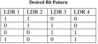
In the setup of the hard ware for the greater application of this project, the LDRs must be placed on the surface of a large curvature. And the mechanism should be done so that any immediate two LDRs remain active at a time. And the stepper motor will follow the bit pattern of the, and the solar panel connected on the shaft of the stepper will always face the sun normally. The LDR combination plays the vital role. Actually these combinations of signals are fed to the microcontroller 8051 and this directs the motor
associated to it. The required bit pattern is shown in TABLE I.
Table I Desired Bit Pattern
LDR 1 LDR 2 LDR 3 LDR 4
1 1 0 0
0 1 1 0
0 0 1 1
[image:1.612.360.530.569.646.2]International Journal of Emerging Technology and Advanced Engineering
Website: www.ijetae.com (ISSN 2250-2459,ISO 9001:2008 Certified Journal, Volume 4, Issue 12, December 2014)
404
When the stepper motor gets the last bit sequence of the table, the stepper motor will move to its initial position again follow these steps again, as the sun traverse from the beginning in next day.III. COMPONANTS USED
The major components of this system are as follows.
1. Microcontroller 8051 (Atmel 89C51 used)
2. Comparator LM324
3. LDRs
4. Motor driver L293D
5. Stepper motor
Other auxiliary components are-
1. Resistor (10KΩ. 1KΩ.)
2. Capacitor (10µF, 33pF)
3. Crystal oscillator (11.0592 MHz)
4. 5V and 6V power supply
Except these components the connecting wire, circuit board other devices are used. A USB based Superpro 280U universal programmer is used to ‗burn‘ the chip (to load the program in the chip. A PC with two software, compiler (ASM) notepad and 8052 simulator is needed.
IV. DETAILED DESCRIPTION OF THE SYSTEM
The complete circuitry of this project mainly can be shown in three parts. These are:
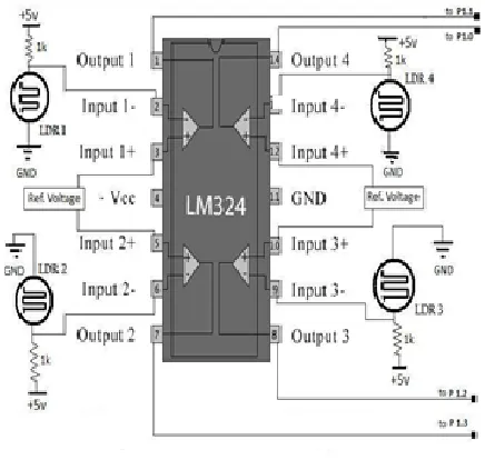
The sensor and comparator part: In this figure how we are getting the output from the LDR through a comparator LM324 by comparing with the reference voltage set by the potentiometer, and given to the Port 1 of AT89C51 is shown. Firstly four LDR are connected to the comparator. we are getting output of the LDR through 1k ohm resistance. The output from this LDR is given to the comparator LM324. Four LDR are used here and all of them connected in this similar way. The output of LDR is given to the inverting terminal of the op-amp of the comparator. LM324 has four comparators in it.
Input to the comparator is given by setting a reference voltage. Reference voltage was set at 2.6 volt. As the light perpendicular to any LDR the corresponding output from the comparator is obtained. The LDR that is used here gives output voltage 2.00 volts when having perpendicular light on it. These outputs are given to the port 1 of microcontroller AT89C51.The circuit diagram of LM324 is shown in Fig. 2.
Fig.2 LM324 and comparator circuit
The Microcontroller part: In the figure the interfacing
circuitry of the Unipolar Stepper Motor with
[image:2.612.322.540.232.439.2]International Journal of Emerging Technology and Advanced Engineering
Website: www.ijetae.com (ISSN 2250-2459,ISO 9001:2008 Certified Journal, Volume 4, Issue 12, December 2014)
[image:3.612.53.258.151.565.2]405
Fig. 3 Total circuit diagram
[image:3.612.323.565.153.278.2]Motor driver L293D with stepper motor part: The L293D is a quadruple high-current half-H driver designed to provide bidirectional drive currents of up to 600-mA at voltages from 4.5 V to 36 V. It is designed to drive inductive loads such as relays, solenoids, dc and bipolar stepping motors, as well as other high-current/high-voltage loads in positive-supply applications. There are three ways to drive unipolar stepper motors (one phase on full step, two phases on full step, or half step), each one has some advantages and disadvantages. In this project two phase full step mode is used.
Table II
One Phase on Sequence (Full Step)
Step 1a 1b 2a 2b
1 1 0 0 1
2 1 1 0 0
3 0 1 1 0
4 0 0 1 1
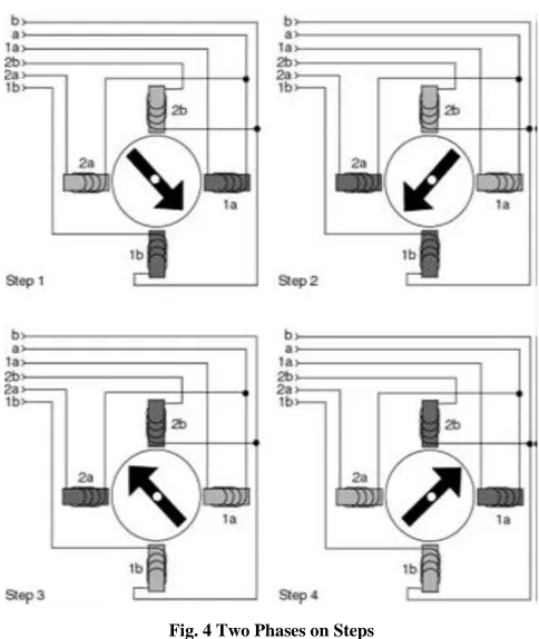
In two phase mode, successive pairs of adjacent coils are energized in turn, motion is not as smooth as in one phase mode, power consumption is more important but it produces greater torque As in one phase mode, applying the steps in order makes the stepper motor run clockwise and reversing order makes it turn counter-clockwise. The diagram of two phases is shown in Fig. 4.
Fig. 4 Two Phases on Steps
[image:3.612.322.564.365.652.2]International Journal of Emerging Technology and Advanced Engineering
Website: www.ijetae.com (ISSN 2250-2459,ISO 9001:2008 Certified Journal, Volume 4, Issue 12, December 2014)
[image:4.612.49.288.326.482.2]406
As we have seen that in half mode, the number of steps taken by the motor to complete one revolution gets doubled, so step angle reduces to half. As in above examples, Stepper Motor rotating in full mode takes 4 steps to complete a revolution, So step angle can be calculated as… Step Angle ø = 360° / 4 = 90° and in case of half mode step angle gets half so 45°.So this way we can calculate step angle for any stepper motor[8]. In morning when sun rises in the east 1st and 2nd LDR getting maximum intensity of light the motor rotates in a specified angle. Then sometimes latter 2nd and 3rd LDR will get maximum light then stepper motor rotates next specified angle. Similarly next 3rd and 4th LDR will get maximum light. After sun set in the west stepper motor return back means solar panel will be at initial position. The photographic view of the hardware is shown in Fig. 5.Fig. 5 Photographic view of total hardware
V. SOFTWARE PART
The microcontroller chip AT89C51 is directed as the program in its flash memory instructs it. So it is obvious to load the program into the chip. Program is written in ASM notepad and compiled. If any compilation error occurs, then it is debugged. Then the HEX-code is generated. Then the program is simulated in 8052 simulator. This gives an opportunity to see what will be the result of the code. If the code gives desired result then the USB based superpro is used to load the program; or to ‗burn‘ the chip. USB based superpro is basically a universal programmer. After downloading the HEX code in the chip is again connected to the main circuit.
VI. CONCLUSION
In this project a solar tracker has been developed to increase the amount of power generated by the solar panel as the sun traverses across the sky. An 8051 microcontroller was used to control the movement of the solar panel. The system is designed to be autonomous; such that energy generated by the solar panel would be used to charge two lead acid batteries. In this project some difficulties regarding the placement or the LDRs is faced, so that at a same time more than two LDR do not get activated. All the readings are taken very carefully during the project to eliminate the errors as many as possible. Solar Energy is one of the most popular renewable sources nowadays. It is being widely used also, and within some more years it will be very popular that it will be used for many purposes, in industries and household as well. So it is most important fact to utilize the maximum energy of the sun so that maximum power can be generated. The thought behind this project is also derived from this fact. In many places experiment is being done on this fact how it is possible to make full use of the day light. In many places application of this project can be seen also. This project has got a bright future scope further. Accuracy of this solar panel can be increased further and number of steps can be increased as well to get more accurate desired output. Timer circuit can also be integrated with this so that this system responses more accurately. Even in a cloudy day when intensity of sunlight may vary at different time of a day, the timer circuit can be more that handy to drive the solar panel correctly in that low light. As per energy concerned solar energy is one of the most promising energy which is going to be a main source of energy in near future.
REFERENCES
[1] B.Suchitha Samuel, J.Mrudula, ―Design of Intelligent Solar Tracker
Robot for Surveillance,‖ International Journal of Advanced Research in Electrical, Electronics and Instrumentation Engineering, Vol. 2, Issue 10, October 2013.
[2] Bhavesh Pandey1, Anita Agrawal, ―Automatic Sun Tracking System
Using PSoC,‖ International Journal of Innovative Research in Science, Engineering and Technology, Vol. 1, Issue 1, November 2012.
[3] Sobuj Kumar Ray, Md. Abul Bashar, Maruf Ahmad & Fahad Bin
Sayed , ―Two Ways of Rotating Freedom Solar Tracker by Using ADC of Microcontroller ‖, Global Journal of Researches in Engineering General Engineering‖, Volume 12 Issue 4 Version 1.0 Year 2012.
[4] Mazidi Md.Ali, Mazidi J.G.,―The 8051 Microcontroller and
International Journal of Emerging Technology and Advanced Engineering
Website: www.ijetae.com (ISSN 2250-2459,ISO 9001:2008 Certified Journal, Volume 4, Issue 12, December 2014)
407
[5] kais i. abdul-lateef, ―a low cost single-axis sun tracker system using
pic microcontroller,‖ diyala journal of engineering sciences, vol. 05, no. 01, pp.65-78, june 2012.
[6] Meghana Sharma, ―An Efficient Low Cost Solar Tracker Using
Microcontroller,‖ IOSR Journal of Electrical and Electronics Engineering (IOSR-JEEE), Volume 9, Issue 4 Ver. V (Jul – Aug. 2014), PP 37-40.
[7] Mostefa Ghassoul, ―Design of an Automatic Solar Tracking System
to Maximize Energy Extraction,‖ International Journal of Emerging Technology and Advanced Engineering, Volume 3, Issue 5, May 2013.
[8]
http://www.8051projects.net/stepper-motor-interfacing/step-sequence.php
[9] http://www.hbeonlabs.com/reports/Time Operated Solar Tracking
System_Report.pdf
[10] http://www.icee.usm.edu/ICEE/conferences/asee2007/papers