International Journal of Emerging Technology and Advanced Engineering
Website: www.ijetae.com (ISSN 2250-2459,ISO 9001:2008 Certified Journal, Volume 3, Issue 9, September 2013)
44
Operating Strategies for Stabilizing the Operation of a Micro
Grid with Various Distributed Generation Sources
San-Yi Lee
1, Wen-Chih Yang
2 1,2Department of Electrical Engineering, Taipei Chengshih University of Science and Technology, Taiwan, R.O.C.
Abstract—A micro grid (MG) needs a suitable operating
strategy to maintain its operation stably. However, the development of an operating strategy for a MG depends deeply on the type and number of distributed generation sources (DGSs). For this reason, this work develops four operating strategies for a MG with one or multi DGSs. The DGSs in MGs can be sustained energy sources (SESs) or intermittent energy sources (IESs). The proposed operating strategies can be used to maintain the stability of MGs effectively. To examine the practicability of these operating strategies, a sample MG is employed and is simulated via computer software. The important simulation results are presented and discussed in this paper.
Keywords—Micro grid, Distributed generation source, Sustained energy source, Intermittent energy source, Operating strategy.
I. INTRODUCTION
A micro grid (MG) is a controllable small-scale power system [1]. It generally comprises distributed generation sources (DGSs), energy storage devices (ESDs), controllers, switchgears, protective devices, and loads, among others [2]. It can be applied to remote locations to supply electricity to customers or can be implemented in utility power systems to increase their reliability. The implementation of MGs can heighten the penetration of
DGSs in the grids of utilities, reduce the emission of CO2,
and protect the environment. Hence, the concept of MG is currently popular in utilities and with customers [3-5].
The DGSs in MGs can be sustained energy sources (SESs), such as a diesel engine generator (DEG), internal combustion engine generator (ICEG), micro turbine (MT), gas turbine (GT), or fuel cell (FC), or intermittent energy sources (IESs), such as wind turbine (WT), photovoltaic (PV), hydraulic generator (HG), wave-energy generation system (WEGS), or biomass generation system (BGS) [6,7]. One or more DGSs can be used simultaneously. A MG consists of different types of DGSs, and its operating condition is different as well.
Hence, developing a suitable operating strategy for MGs is an important task for electric utilities and is useful for MG operators.
In this paper, four operating strategies for MGs are presented. The first is suitable for MGs containing only one SES; the second is suitable for MGs containing one IES; the third is suitable for MGS containing two SESs; and the fourth is suitable for MGs containing one SES and one IES. To examine the practicability of these operating strategies, a sample MG is employed by this paper and is simulated using professional software, MATLAB/Simulink. The simulation results, such as bus voltages, feeder currents, grid’s power flow, and frequency, are presented and discussed. These operating strategies and simulation results are useful for operators of MGs because they can be used to maintain their MGs operating stably.
II. COMBINATIONS OF DGSS IN AMG
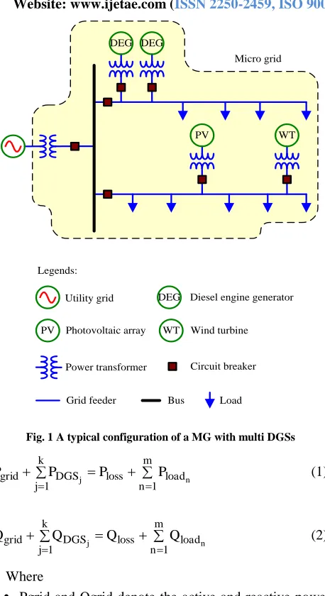
A MG may comprise one or more DGSs. The DGSs can be SESs, IESs, or both. Fig. 1 shows a typical configuration of a MG with multi DGSs. The DGSs comprise two DEGs, one PV and one WT. The DEGS are SESs, whereas the PV and the WT are IESs.
The operating conditions of a MG with only one type of DGS are relatively simple. Hence, the operating strategy for this kind of MG is simple as well. However, the operating conditions of a MG with both SESs and IESs are complex. As such, the operating strategy for this kind of MG is also complex [8,9].
III. OPERATING RESTRICTIONS FOR MGS
A MG can be operated either independently or with a utility grid in parallel. The former is called the islanded mode, and the latter is called the grid-connected mode [10]. Whatever the operating mode of a MG is, three operating restrictions should be followed [11,12].
International Journal of Emerging Technology and Advanced Engineering
Website: www.ijetae.com (ISSN 2250-2459,ISO 9001:2008 Certified Journal, Volume 3, Issue 9, September 2013)
45
Diesel engine generator Utility grid
Power transformer
Load Circuit breaker
Bus Legends:
Photovoltaic array
PV WT
DEG DEG
Micro grid
DEG
PV WT Wind turbine
[image:2.612.55.284.122.542.2]Grid feeder
Fig. 1 A typical configuration of a MG with multi DGSs
m
1
n load
loss k
1
j DGS
grid P j P P n
P (1)
m
1
n load
loss k
1
j DGS
grid Q j Q Q n
Q (2)
Where
Pgrid and Qgrid denote the active and reactive power
injected into a MG from a utility grid, respectively;
PDGSj and QDGSj denote the active and reactive
power outputs of the jth DGS in a MG, respectively; Ploss and Qloss denote the total active and reactive
power losses in a MG, respectively;
Ploadn and Qloadn denote the active and reactive
power demands of the nth load in a MG, respectively;
j is the number of DGSs in a MG;
k is the amount of DGSs in a MG;
n is the number of loads in a MG; and
m is the amount of loads in a MG.
Second, each bus voltage should not exceed its tolerance. That is, (3) must be satisfied.
max i i min
i V V
V (3)
Where
|Vi|min、|Vi|max denote the lower and upper voltage
limits of the ith bus in a MG, respectively; and
|Vi| denotes the voltage magnitude of the ith bus in a
MG.
Third, each feeder current should not exceed its thermal limit. That is, (4) must be satisfied.
thr i
i I
I (4)
Where
|Ii|thr denotes the thermal limit of the ith feeder in a MG;
and
|Ii| is the current magnitude of the ith feeder in a MG.
IV. PROPOSED OPERATING STRATEGIES FOR MGS
A MG can be operated either independently or with a utility grid in parallel. The former is called the islanded mode, and the latter is called the grid-connected mode [10]. Whatever the operating mode of a MG is, three operating restrictions should be followed [11,12].
4.1A MG containing one SES
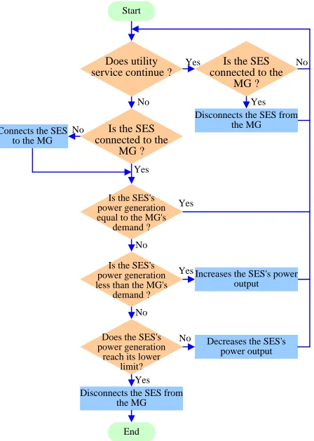
A SES can be a DEG, ICEG, MT, or FC, etc. The fuel costs of SESs are generally higher than those of utilities. Thus, SESs should be disconnected from their MGs to reduce operating costs and environmental pollution while the MGs are operated in the grid-connected mode. In contrast, SESs should be connected to their MGs while the MGs are operated in the islanded mode because utility grids cannot supply electricity to customers in MGs. Based on the operating conditions described previously, the operating strategy for a MG containing one SES is developed, as shown in Fig. 2. Some assumptions adopted by this paper are described as follows:
1. The SES has the ability to control the voltage and frequency of the MG within an allowable range while the MG operates in the islanded mode. A v-f controller has been installed in the SES.
2. The SES also has the ability to reconnect to its MG at
any time. A synchronized phasor measurement unit and switchgear have been installed in the SES.
3. The SES has enough capacity to meet the peak
demand of the MG while the MG is operated in the islanded mode.
International Journal of Emerging Technology and Advanced Engineering
Website: www.ijetae.com (ISSN 2250-2459,ISO 9001:2008 Certified Journal, Volume 3, Issue 9, September 2013)
46
Does utilityservice continue ?
No
Is the SES connected to the
MG ?
No
Yes Yes
Disconnects the SES from the MG
Is the SES's power generation less than the MG's
demand ?
Increases the SES's power output
No Yes
Does the SES's power generation
reach its lower limit?
Decreases the SES's power output
End Disconnects the SES from
the MG Yes
No Is the SES's power generation equal to the MG's
demand ? Yes
No
Is the SES connected to the
MG ?
No
Yes Start
Connects the SES to the MG
[image:3.612.56.280.136.450.2]
Fig. 2 The operating strategy for a MG containing one SES
4.2A MG containing one IES
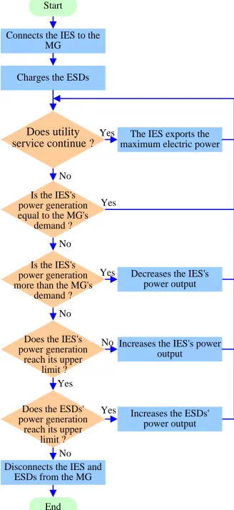
An IES can be a WT, PV, HG, WEGS, or BGS, etc. IESs incur almost no fuel cost and they do not emit pollutants because they use natural energy to produce electric power. Hence, they should be connected to their MGs while the MGs are operated in grid-connected mode. In doing so, the operating cost of MGs can be reduced, and the environment can be protected. However, IESs are not stable electric sources. They cannot supply stable electricity for long because of the effects of weather and the environment. Thus, IESs have to be operated with ESDs, such as batteries, simultaneously. Based on the operating restrictions, the operating strategy for a MG containing one IES is developed, as shown in Fig. 3. Some assumptions adopted by this paper are described as follows:
1.The IES exports electric power using a power
converter. The power converter has the ability to control the voltage and frequency of the MG within an allowable range while the MG is operated in islanded mode.
2. The power converter of the IES does not control the voltage and frequency of the MG while the MG is operated in grid-connected mode. It only exports the maximum electric power according to the input energy
3. The rating capacity of the IES is enough for the peak
demand of the MG while the MG is operated in islanded mode.
4. The ESD also uses a power converter to export
electric power. The ESD does not have the ability to control the voltage and frequency of the MG whether the MG is operated in islanded or grid-connected mode.
5. Both the IES and ESD are limited by maximum
power output.
6. Both the IES and ESD are installed with a
synchronized phasor measurement unit and
switchgear. Hence, they can reconnect to their MG at any time.
7. This operating strategy does not adopt any load
shading strategy.
4.3A MG containing multi SESs
When a MG contains two or more SESs, its operating condition becomes complex. Two operating strategies are available for this kind of MG. First, one of the two SESs is reconnected initially to its MG while the MG is operated in islanded mode. Some loads in the MG are then restored according to the preplanning restoration scheme. After the voltage and frequency of the MG stabilize, the other SES is reconnected to the MG, and then restoring the residual loads of the MG. Second, the two SESs are reconnected gradually to its MG before load restoration. After the voltage and frequency of the MG stabilize, the loads of the MG are restored at the same time.
Both strategies have their advantages and disadvantages. The former needs a long duration to restore its MG. However, its restoring process is more reliable than that of the letter. In contrast, the latter spends only a short time for restoring. However, the voltage or frequency of the MG may oscillate largely when most of the loads are reconnected to the MG simultaneously. Once the oscillation exceeds the tolerance of the MG, the starting work fails.
International Journal of Emerging Technology and Advanced Engineering
Website: www.ijetae.com (ISSN 2250-2459,ISO 9001:2008 Certified Journal, Volume 3, Issue 9, September 2013)
47
1.The capacity of each SES is smaller than the peak load demand of its MG. However, the total generation capacity of the two SESs is larger or equal to the peak load demand of its MG.
2.The two SESs export electric power in accordance
with their voltage-drop characteristics.
3.Both SESs have the ability to control the voltage and
frequency of the MG within an allowable range while the MG is operated in islanded mode.
4.Both SESs have the ability to reconnect to their MG at any time.
5.Each SES is limited by minimum power output.
Connects the IES to the MG
Charges the ESDs
Does utility service continue ?
No
The IES exports the maximum electric power Yes
Is the IES's power generation more than the MG's
demand ?
Decreases the IES's power output
No Yes
Does the IES's power generation
reach its upper limit ?
Increases the IES's power output
Yes No Is the IES's power generation equal to the MG's
demand ? Yes
No
Does the ESDs' power generation
reach its upper limit ?
Increases the ESDs' power output
No Yes
Disconnects the IES and ESDs from the MG
Start
[image:4.612.357.531.138.552.2]End
Fig. 3 The operating strategy for a MG containing one IES
Does utility service continue ?
No
Is the first SES connected to the
MG ?
No
Yes Yes
Disconnects the first SES from the MG Start
No
Yes Disconnects the second
SES from the MG
Is the second SES connected to the
MG ? Is
the first SES connected to the
MG ?
No Yes
Connects the first SES to the MG
No
Is the second SES connected to the
MG ?
Yes
Is the SESs' total power generation
less than the MG's demand ?
Increases each SES's power output
No Yes
Does every SES's power generation reach its
lower limit?
Decreases each SES's power output
End Disconnects all SES from
the MG Yes
No Is the SESs' total power generation
equal to the MG's demand ?
Yes
No Yes Connects the second SES
[image:4.612.83.247.284.641.2]to the MG
Fig. 4 The operating strategy for a MG containing two SESs
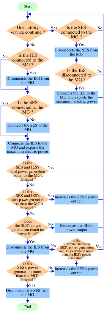
4.4A MG containing bothSES and IES
International Journal of Emerging Technology and Advanced Engineering
Website: www.ijetae.com (ISSN 2250-2459,ISO 9001:2008 Certified Journal, Volume 3, Issue 9, September 2013)
48
However, the IES should be connected to its MG in islanded or grid-connected mode to supply green energy and to save fuel cost. In practice, IESs are used as the major electric sources of MGs when the MGs are operated in islanded mode. They are also used as auxiliary electric sources when the MGs are operated in islanded or grid-connected mode. The operating strategy for a MG containing one SES and one IES is developed in this paper, as shown in Fig. 5. Some assumptions adopted by this paper are as follows:
1. The SES can control the voltage and frequency of the
MG within an allowable range while the MG is operated in islanded mode. The generation capacity of the SES is larger than the peak demand of the MG.
2. The IES connects to its MG through a power
converter. However, the power converter does not have the ability to control the voltage and frequency of the MG whether the MG is operated in islanded or grid-connected mode.
3. The IES exports maximum electric power in
accordance with the input energy. The output power changes with the change in its input energy.
4. The SES is limited by minimum power output, but
the IES is not.
5. Both SES and IES have the ability to reconnect to their MG at any time.
V. THE SAMPLE MGFOR EXAMINATION
In practice, a MG is generally composed of both SES and IES. Hence, the sample MG is designed to have one SES and one IES. The structure, parameters, and equivalent model of the sample MG are described as follows.
5.1Structure and parameters of the sample MG
Fig. 6 shows the one-line diagram of the sample MG used in this paper. The power transformer P1 is used to
connect the utility grid and the sample MG. Its rating and parameters are shown in Table I. The sample MG has two DGSs: one is a DEG with a rating capacity of 150 kVA, and the other is a PV with the same rating capacity of 150 kVA. Each DGS is connected to the sample MG through a power transformer. The power transformers P2 and P3 are
used as isolation devices. Hence, their voltage ratings on the primary and secondary sides are identical. The power transformers P2 and P3 have the same size; their parameters
are shown in Table II. Moreover, the sample MG has some loads. These loads are fed with electricity by two distribution feeders, the sample feeders F1 and F2. The
parameters of the two sample feeders are identical and are shown in Table III.
To keep the voltage and frequency of the sample MG stable, the DEG has a V-f controller, but the PV does not.
Does utility service continue ?
No
Is the SES connected to the
MG ?
No
Yes Yes
Disconnects the SES from the MG Start
No
Yes Connects the IES to the
MG and exports the maximum electric power
Is the IES disconnected to
the MG ? Is the IES
connected to the MG ?
Yes No
Disconnects the IES from the MG
No
Is the SES connected to the
MG ?
Yes
Yes Connects the SES to the
MG
Connects the IES to the MG and exports the maximum electric power
Is the SES and IES's total power generation
equal to the MG's demand ?
Yes
Is the SES and IES's total power generation less than the MG's
demand ? No
Yes
Does the SES's power generation reach its
lower limit?
Decreases the SES's power output
End Disconnects the SES from
the MG No No
Disconnects the IES from the MG
Yes
Is the SES's power generation more
than the MG's demand ?
Yes No
Increases the SES's power output
Increases the SES's power output
Is the difference between SES's power generation and MG's demand more than the IES's power
generation ?
[image:5.612.356.531.162.685.2]No
International Journal of Emerging Technology and Advanced Engineering
Website: www.ijetae.com (ISSN 2250-2459,ISO 9001:2008 Certified Journal, Volume 3, Issue 9, September 2013)
49
DEGPV
P1
P2
P3
Diesel engine generator Utility grid
Power transformer
Load Circuit breaker
Bus Legends:
Photovoltaic array DEG
PV
Grid feeder
Feeder F1
Feeder F2
CB1
CB2
CB3
CB4
[image:6.612.60.279.121.396.2]CB5
Fig. 5 One-line diagram of the sample MG
5.2Equivalent model of the sample MG
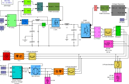
This paper develops an equivalent model of the sample MG for computer simulation. The simulation tool adopted by this paper is MATLAB/Simulink [13,14]. Fig. 7 shows the blocks of the equivalent model of the sample MG built in MATLAB/Simulink. The equivalent model of each component is provided by SimPowerSystems in Simulink, in which the grid of the utility is denoted by a constant voltage source with constant impedance.
Table I
Parameters Of The Power Transformer P1 In The Sample MG
Capacity (kVA)
Primary voltage
(kV)
Secondary voltage
(V)
Winding impedance
(%)
Winding connection
[image:6.612.45.291.545.667.2]150 11.4 380 1.65+j2.5 Wye-delta
Table II
Parameters Of The Power Transformers P2 And P3 In The Sample
MG
Capacity (kVA)
Primary voltage
(kV)
Secondary voltage
(V)
Winding impedance
(%)
Winding connection
150 380 380 1.35+j1.9 Wye-delta
Table III
Parameters of the distribution feeder in the sample MG
Material
Cross section (mm2)
Impedance ()
Thermal capacity
(A)
Copper 200 0.101+j0.092 300
VI. SIMULATION RESULTS AND DISCUSSIONS
To examine the practicability of the proposed operating strategies under different combinations of DGSs, two simulation scenarios are carried out: one is for the operating strategy of a MG with one DEG, and the other is for the operating strategy of a MG with one DEG and one PV. The simulation results are organized and presented as follows.
6.1Scenario 1
In this scenario, the PV in the sample MG is removed. The sample MG only has one DGS, i.e., the DEG. Hence, the operating strategy of a MG described in subsection 4.1 is adopted in the simulation scenario. The operating conditions of the sample MG are given below. The simulation results are presented in Figs. 8 to 11.
1. At 0 s: The utility grid and DEG operate in parallel to
supply the sample MG. The total load of the sample MG is 100 kVA with 0.8 lagging power factor. The sample MG is operated in grid-connected mode.
2. At 1 s: The DEG is disconnected from the sample MG
because the sample MG is operated in grid-connected mode.
3. At 2 s: The utility grid trips because of a fault. The sample MG loses power service. All loads of the sample feeders are shed in this duration.
4. At 3 s: The DEG starts to supply electric power to the
sample MG. The sample MG is operated in islanded mode in this duration.
5. At 5 s: The circuit breaker CB4 closed. Hence, the
loading of 50 kVA of the sample feeder F1 is restored.
6. At 6 s: The circuit breaker CB5 closed. Hence, the
loading of 50 kVA of the sample feeder F2 is restored
as well.
7. At 7 s: The loading of the sample MG is reduced by
50 kVA because the circuit breaker CB4 opened.
8. At 9 s: The loading of the sample MG is again
reduced by 50 kVA because the circuit breaker CB5
opened as well.
International Journal of Emerging Technology and Advanced Engineering
Website: www.ijetae.com (ISSN 2250-2459,ISO 9001:2008 Certified Journal, Volume 3, Issue 9, September 2013)
50
1.0wref (pu)1 Discrete, Ts = 1e-005 s.
pow ergui 1 Vtref (pu)1 1 Vref (pu) v + -Vpv Vabc (pu)
Vd_ref (pu) Vabc_inv m Voltage Regulator g A + -Universal Bridge 1 arm z 1 N A B C TaiPower A B C A B C TL3 A B C A B C TL2 30 T Pm Vf _ m A B C
SM 100 kVA
Signal(s) Pulses PWM Generator g A B C + -PWM IGBT Inverter Vm Ga Ta Im
PV array AVabc
B C a b c Measure In Mean Mean Value1 In Mean Mean Value Ipv Vpv M MPPT A B C A B C LC Filter1 L1 L 450 Ga Uref Pulses Discrete PWM Generator wref Vtref m Pm Vf Vt w Diesel Engine Speed & Voltage
Control
s
-+
Controlled Current Source
C4
C3 C2 C1
A B C 80 kW 380 V rms 60 Hz1 A B C 80 kW 380 V rms
60 Hz A B C a b c 3-Phase Breaker6
A B C
a b c
3-Phase Breaker5 A B C a b c 3-Phase Breaker4 A B C a b c 3-Phase Breaker2
A B C 10 KW
[image:7.612.79.531.143.439.2]Pmec (pu) Vf (pu)
Fig. 7 An equivalent model of the sample MG
In this scenario, the sample MG is operated in islanded mode at 3 s. Afterwards, the DEG supplies the entire sample MG. Fig. 8 illustrates the variation of power generation of the DEG with the demand of the sample MG. Fig. 9 shows that the system frequency is affected by the variation of the loading of the sample feeder. When the loading varies significantly, the system frequency varies significantly as well. Figs. 10 and 11 show that the voltage and currents of the sample MG are roughly stable in islanded mode. This finding indicates that SESs are suitable for application to MGs if the capacity of the electric sources is large enough.
6.2Scenario 2
In this scenario, one DEG and one PV are simultaneously connected to the sample MG. The DEG has a V-f controller, but the PV does not. The sample MG has two DGSs. Hence, the operating strategy of DGS described in subsection 4.4 is adopted in this scenario. The operating conditions of the sample MG in Scenario 2 are different from those in Scenario 1, as indicated below.
The simulation results of this scenario are presented in Figs. 12 to 16.
1. At 0 s: The sample MG is supplied by the utility grid.
Its total load is 150 kVA with 0.8 lagging power factor. The sample MG is operated in the grid-connected mode.
2. At 0.1 s: The PV is connected to the sample MG and
supplies 24k W of electric power.
3. At 0.5 s: The utility grid trips because of a fault. The PV supplies electric power to the sample MG continuously.
4. At 0.9 s: The PV is disconnected from the sample MG.
There is no electric source in the sample MG.
5. At 1.2 s: The DEG starts and is connected to the sample MG to supply 150 kVA of electric power. The sample MG operates in the islanded mode in this duration.
6. At 1.5 s: The PV is reconnected to the sample MG to
supply 30 kVA of electric power with 0.8 lagging power factor.
International Journal of Emerging Technology and Advanced Engineering
Website: www.ijetae.com (ISSN 2250-2459,ISO 9001:2008 Certified Journal, Volume 3, Issue 9, September 2013)
[image:8.612.50.287.112.655.2]51
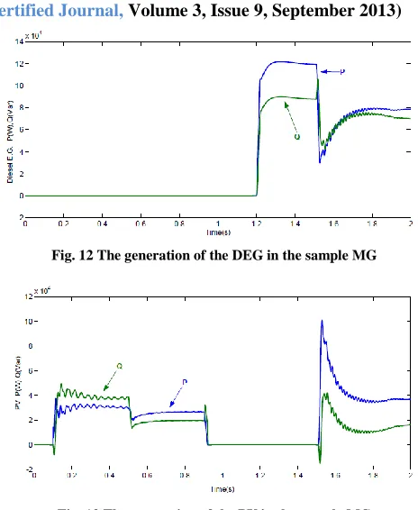
Fig. 8 The generation of the DEG in the sample MGFig. 9 The frequencies at bus 2 of the sample MG
Fig. 10 The voltages at bus 2 of the sample MG
Fig. 11 The currents flowing through bus 3 of the sample MG
[image:8.612.325.557.119.402.2]Fig. 12 The generation of the DEG in the sample MG
Fig. 13 The generation of the PV in the sample MG
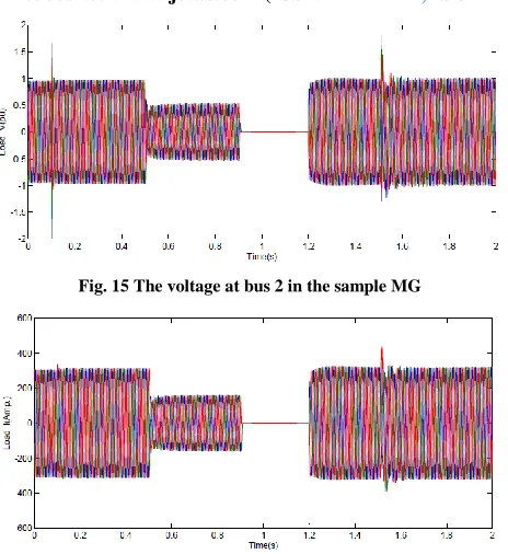
[image:8.612.327.556.584.697.2]In this simulation scenario, the PV operates in parallel with the utility grid at the begging and then trips because the sample MG is operated in islanded mode. The DEG starts to supply the entire sample MG at 1.2 s. The PV then reconnects to the sample MG at the 1.5 s. Figs. 12 and 13 present the variations of the electric power output of the DEG and PV. The electric power output of the PV is not stable from 0.1 to 0.5 s because of the interconnection of the utility grid and the DEG. Fig. 14 shows that the system frequency is affected by the connection of the two DGSs. The frequency varies small except for a short time from 1.2 to 1.6 s. Figs. 15 and 16 illustrate that the voltage of the sample MG is very stable except for a short duration that the PV connects to the sample MG.
International Journal of Emerging Technology and Advanced Engineering
Website: www.ijetae.com (ISSN 2250-2459,ISO 9001:2008 Certified Journal, Volume 3, Issue 9, September 2013)
[image:9.612.54.286.128.381.2]52
Fig. 15 The voltage at bus 2 in the sample MGFig. 16 The current flowing through bus 3 of the sample MG
VII. CONCLUSIONS
Four operating strategies of a MG have been presented in the current paper. The first strategy can be used for MGs with only one SES; the second can be used for MGs with only one IES; the third can be used for MGs with multi SES; and the fourth can be used for MGs with both SES and one IES. SESs and IESs are all important electric power sources for MGs while operating in islanded mode. The SESs can maintain the balance between the power supply and demand, and the IESs can provide clean energy. The concept of MGs is more popular in electric industries [15]. DGSs are expected to play an important role in MGs. Adopting the appropriate operating strategy for a MG is important. Hence, the proposed operating strategies are useful for utilities when operating their MGs in the future.
Acknowledgment
The authors would like to thank the National Science Council of the Republic of China, Taiwan, for financially supporting this research under Contract No. NSC102-3113-P-194-002.
REFERENCES
[1] H. Jiayi, J. Chuanwen and X. Rong, “A Review on Distributed Energy Resources and MicroGrid,” ELSEVIER Renewable and Sustainable Energy Reviews,” Vol. 12, Issue. 9, December 2008, pp.2472-2483.
[2] W. T. Huang, “Study on the Operation of a Low-Voltage AC Microgrid with Multiple Distributed Generations,” WSEAS Transactions on Circuits and Systems, Vol. 9, Issue. 2, December 2010, pp.725-735.
[3] R. H. Lasseter and P. Paigi, “Microgrid: A Conceptual Solution”, IEEE 35th Annual Power Electronics Specialists Conference, Vol. 6, June 2004, pp.4285- 4290.
[4] R. H. Lasseter, “MicroGrids,” IEEE Power and Energy Magazine, Vol. 5, July-August 2007, pp.78- 94.
[5] N. C. Yang and T. H. Chen, “Dual Genetic Algorithm-based Approach to Fast Screening Process for Distributed Generation Interconnections,” IEEE Transactions on Power Delivery, April 2011, Vol. 26, No. 2, pp. 850-858..
[6] W. T. Huang and W. C Yang, “Power Flow Analysis of a Grid-Connected High- Voltage Microgrid with Various Distributed Resources,” In Proceedings of the International Conference on Mechanic Automation and Control Engineering, October 2011, pp.1471-1474.
[7] W. C Yang and W. T. Huang, “Determination of the Maximum Power Generation of Renewable Energy Generating Units in an IslandedMicrogrid,” In Proceedings of the International Conference on Mechanic Automation and Control Engineering, October 2011, pp.1213-1216.
[8] P. Piagi, Microgrid Control, Dissertation, University of Wisconsin Madison, April 2005.
[9] R. H. Lasseter and P. Paigi, Control and Design of Microgrid Components, Final project report, University of Wisconsin Madison, January 2005.
[10] F. Katiraei, M. R. Iravani and P. W. Lehn, “Micro-Grid Autonomous Operation During and Subsequent to Islanding Process,” IEEE Transactions on Power Delivery, Vol. 20, No. 1, January 2005, pp.248-257.
[11] F. D. Kanellos, A. I. Tsouchnikas and N. D. Hatziargyriou, “Micro-Grid Simulation during “Micro-Grid-Connected and Islanded Modes of Operation,” In Proceedings of the International Conference on Power Systems Transients, June 2005, pp.1- 6.
[12] S. Krishnamurthy, T. M. Jahns and R. H. Lasseter, “The Operation of Diesel Gensets in a CERTS Microgrid,” In Proceedings of the IEEE Power and Energy Society General Meeting, July 2008, pp.1- 8.
[13] T. Zhao and Q. Wang, “Application of MATLAB/SIMULINK and PSPICE Simulation in Teaching Power Electronics and Electric Drive System,” In Proceedings of the International Conference on Electrical Machines and Systems, Vol. 3, September 2005, pp.2037-2041.
[14] K. Schoder, A. Hasanovic and A. Feliachi, “PAT: A Power Analysis Toolbox for MATLAB/Simulink,” IEEE Transactions on. Power Systems, Vol. 18, Issue. 1, February 2003, pp.42-47.