International Journal of Emerging Technology and Advanced Engineering
Website: www.ijetae.com (ISSN 2250-2459, ISO 9001:2008 Certified Journal, Volume 7, Issue 5, May 2017)
12
Comparison between Standard Perturb & Observe Technique
and Modified P&O with Fuzzy Logic Control
Nabil M. Elmahjoub
Master Degree in Electrical Power System, Singidunum University, 261a Kumodraška St., Belgrade
Abstract—An alternative energy source has been growing to overcome the persistent shortages and unreliability of power supply. The Photo-Voltaic solar power system (PV) is considered as an important alternative source. Due to the change of power obtained from the solar system and increase in the efficiency of the system, we are required to make an optimization of the system. To achieve that, it is necessary to select one of many Maximum Power Point Tracking techniques that are in use today. In this research, we conduct a general overview at Maximum Power Point Tracking techniques (MPPT) that in common use. We make a comparison between the results obtained from a conventional Perturb & Observe (P&O) method, and the results obtained when fuzzy logic control is added to the same algorithm. This study aims to provide a general overview of the most common MPPT techniques that are used in photovoltaic applications and improve P&O techniques by adding fuzzy logic control.
Keywords— Fuzzy logic control, Incremental Conductance, Maximum power point tracking (MPPT), Perturb and Observe Algorithm, Solar Photovoltaic.
I. INTRODUCTION
The necessity of using a clean electric power can be found in the attempt to try avoiding degrading our environment any more. Sunlight is an excellent source of energy which can be utilized for electric power generation. The maximum power point varies with radiation intensity and temperature, and it is important that any solar photovoltaic (SPV) array is used to its maximum potential by using an appropriate Maximum Power Point Tracking (MPPT) technique. Many research papers have focused on increasing the efficiency of the overall solar PV system by ensuring maximum power capture and have compared MPPT techniques. It has been concluded that the Perturb & Observe (P&O) and Incremental Conductance (IC) algorithms are the most efficient of all the MPPT techniques that have been analysed.
In this paper we present an overview of common MPPT techniques that are used in PV applications and show there is an improvement in the P&O technique when fuzzy logic control is added. The paper is organized as follows: The overall configuration of the SPV system and description of different MPPT techniques and algorithms are described in Section 2.
The proposed MPPT technique with fuzzy logic control is presented in Section 3. Comparison between the proposed method and some previous work is addressed in Section 4. Finally conclusions are presented in Section 5.
II. SOLAR PHOTOVOLTAIC SYSTEM
Among all the renewable energy sources, solar power attracts the most attention, as it is the best promising option that can be applied in industries. Solar energy is abundant, free and clean. This means that solar energy does not make any noise, and it does not send any kind of pollution to the environment. Figure 1 shows the basic diagram of connecting the solar cells into the system, where the solar energy is connected to DC-DC converter and the output is connected to inverter which contains an AC output that is connected to utility grid.
Fig.1, PV connected with Module integrated Inverter, [1].
International Journal of Emerging Technology and Advanced Engineering
Website: www.ijetae.com (ISSN 2250-2459, ISO 9001:2008 Certified Journal, Volume 7, Issue 5, May 2017)
13
Some of the most common applications are hot water, steam, drying and dehydration processes, preheating, concentration, pasteurization, sterilization, washing, cleaning, chemical reactions, industrial space heating, food, plastic, building, textile industry and even business concerns [1].
A. MPPT techniques:
Many MPPT methods have been effectively used in standalone and grid-connected PV power system for slow and smoothly changing radiation. In practical applications, a PV array consists of many PV modules connected in series and in parallel to provide the necessary voltage and/or current. The output power of a PV array decreases considerably due to soiling, cell damage, partial shading, etc. The output power of a PV array has a very significant reduction. The following are some of the MPPT techniques which are suitable for uniform irradiance conditions:
Perturb & Observe (P&O) (hill climbing method);
Incremental Conductance Method;
Fractional Short Circuit Current;
Fractional Open Circuit Voltage;
Intelligent Control;
Neural networks; Fuzzy logic.
The choice of the algorithm depends on the time complexity of the algorithm to track the MPP, implementation cost and ease of implementation [2].
1.
Perturb & Observe method
In the P&O method, Fig. 2, a small voltage perturbation in a certain working voltage of the PV array is made simultaneously while observing the change in direction of output power. Selecting the appropriate step size is the key for P&O method to achieve the desired effect. P&O involves perturbation in the PV array voltage to achieve the MPP. When connected to a DC–DC converter, perturbing the duty ratio of power converter perturbs the PV array current and consequently perturbs the PV array voltage.
It is known that when incrementing the voltage it increases the power when operating on the left of the MPP and decreases the power when on the right of the MPP. Therefore,
(1)
Where, is the reference value of the voltage, is
the change in voltage and
the rate of change of power
with voltage.
In this method, the sign of the last perturbation and the sign of the last increment in the power are used to decide what the next perturbation should be. On the left of the MPP incrementally increasing the voltage increases the power whereas on the right decreasing the voltage increases the power.
[image:2.612.335.548.294.496.2]If there is an incremental change in the power, the perturbation should be kept in the same direction and if the power decreases, then the next perturbation should be in the opposite direction. Based on these observations, the algorithm is implemented. The process is repeated until the MPP is reached. Then the operating point oscillates around the MPP [2, 3].
Fig. 2, Perturb & Observe method, [2].
The P&O algorithm begin with the characteristic Current-Voltage (IV) curve of the PV array. It will start with a definite value called the initial duty cycle. Next we calculate the power, which gives either a positive or a negative perturbation. If the value of the power is bigger than the old value then we will continue with the same direction on the curve, but if we find that the old value is bigger than the new we will change direction. At the same time we have to observe any change of the irradiance voltage. The iterations continue depending on irradiance condition, until we got the maximum power.
2.Incremental Conductance
International Journal of Emerging Technology and Advanced Engineering
Website: www.ijetae.com (ISSN 2250-2459, ISO 9001:2008 Certified Journal, Volume 7, Issue 5, May 2017)
14
The incremental conductance algorithm is derived by differentiating the PV array power with respect to voltage and setting the result equal to zero [2]. This is shown in Eq. (2)
⁄
;
and,
;
Therefore,
If (
;
If (
;
Where, is the reference value of the voltage, is
the change of voltage values, is the instantaneous
conductance,
is the incremental conductance and is
the change of the power with respect to the voltage.
3. Fractional short circuit current
The method shows that the current at maximum power point is approximately linearly related to the short circuit current of the PV array.
is between 0.78 and 0.92. The accuracy of the method and tracking efficiency depends on the accuracy of and periodic measurement of short circuit current [4].
4. Fractional open circuit voltage
The method offers the ratio between array voltages at maximum power to its open circuit voltage is nearly constant.
This factor has been reported to be between 0.71 and 0.78. Once the constant is known, is computed by measuring periodically.
Although the implementation of this method is simple and cheap, its tracking efficiency is relatively low due to the utilization of inaccurate values of the constant in the computation of [4].
5.Intelligent controlling based MPPT
The MPPT is a technique that can be classified into three methods:
5.1 Fuzzy logic control (FLC) based MPPT.
[image:3.612.48.258.186.401.2]The fuzzy logy controller (FLC) changes the duty cycle of the converter according to the voltage error input and change in error input such that panel output voltage becomes equal to the voltage corresponding to maximum voltage. The voltage error is obtained by comparing the instantaneous array voltage with the reference voltage; the reference voltage corresponds to the maximum array voltage at a particular solar insolation at that instant. This maximum voltage and the reference voltage change according to solar insolation as shown on Fig. 3, [5, 6].
Fig. 3, General diagram of a fuzzy controller, [6]. 5.2 Artificial neural network (ANN) based MPPT
[image:3.612.333.566.368.426.2]The ANNs are new emerging technology used to solve complex problems. ANN are used for the on-line estimation of the insolation-dependent reference voltage, since MPP voltages are non-linearly related to the solar insolation linear function approximation techniques that are not suitable. ANN uses feed- forward neural network. Input of ANN consists of solar irradiance and cell temperature. Output voltage at maximum power point is calculated for different inputs, Fig. 4, [7].
Fig. 4, Schematic arrangement of PV system using Neural network MPPT, [7].
International Journal of Emerging Technology and Advanced Engineering
Website: www.ijetae.com (ISSN 2250-2459, ISO 9001:2008 Certified Journal, Volume 7, Issue 5, May 2017)
15
In this way transient is sensed, reference voltage is changed accordingly and new MPP is tracked. This method tracks MPP and nonlinearity and is considered more robust than conventional nonlinear controllers [5].
III. PROPOSED MPPTTECHNIQUE WITH FUZZY LOGIC
CONTROL
The basic concept behind the proposed MPPT method has been inferred from problems arising with constant duty cycle increment usage in the classic P&O algorithm. Namely, if a large duty cycle increment employs a faster power point, tracking can be expected. However, tracking can be less precise and oscillations in output power may be observed. If a small duty cycle increment is used, a more precise response, with smaller oscillations is to be expected, but usually at the expense of slower maximum power point tracking. Using Matlab Simulation we get faster tracking and better precision using Fuzzy logic control.
Improvement to the P&O algorithm can be realized if the duty cycle increment is made a variant. If during transients, that is the PV panel is exposed to substantial changes in irradiance, temperature or other factors that influence maximum power, the increment in the duty cycle will be large and a fast response will be obtained. On the other hand, if the working point is close to MPP and in cases where little or no change in the environmental parameters is observed, the duty cycle will be small with a precise response and without oscillations in output power. There will be some parameters for which the duty cycle should be changed, such parameters as those that change the PV panel output power. Again, if the change in output power is substantial(as during transients), the duty cycle should generally be large, but if the change in output power is small then duty cycle increment should also be small.
This approach can be realized by using a FLC which judges the rate of change in the output power and changes the increment in duty cycle accordingly, while the basic principle behind P&O algorithm stays the same.
A. Modeling and simulation
[image:4.612.333.561.130.201.2]The block diagram of the PV simulation system used in this work is shown in Fig. 5. The module contains the PV panel, boost converter with IGBT switch, and load. The hardware specification of the computer used for simulation is Intel{R} Core(TM) i3-5005U CPU @2.00GHZ.
Fig. 5, Block diagram of Controlling PV solar system by MPPT.
In this work, the simulation model is developed with MATLAB/SIMULINK. The simulation model of the proposed method is shown in Fig.
3.1.2
and the waveforms obtained are shown in Fig.4.1
. The proposed circuit has an independent DC source which is supplied from photovoltaic cell. The PV cell temperature is maintained constant at 25 degree Celsius, and the solar intensity is varied in steps up to the rated value of 1000W/meter square. The open circuit voltage and the short circuit current is 7.84 A. The inputs are fed by voltage and current from the PV terminals, while the output provides the duty cycle for the boost converter. The main components used in the simulation model of Fig. 6, are as follows:1- PV cells; 2- Fuzzy logic controller; 3- Input variables; 4- Output
Fig. 6, the simulation model
IV. COMPARISON BETWEEN THE PROPOSED METHOD AND
SOME PREVIOUS WORK
[image:4.612.334.561.392.533.2]International Journal of Emerging Technology and Advanced Engineering
Website: www.ijetae.com (ISSN 2250-2459, ISO 9001:2008 Certified Journal, Volume 7, Issue 5, May 2017)
16
Bhatnagar and Nema [5] provided a comparison between some of MPPT techniques in the basis of sensors used, cost, complexity, application, accuracy and speed.
The results obtained by Faranda and Leva [8] indicated that the P&O and IC algorithms are, generally, the most efficient MPPT techniques and as they do not required additional static switches their relative costs are not high. Zainudin and Mekhilef [9] compared two popular MPPT controllers, P&O and the Incremental Conductance Controller. They concluded that for all the cases they examined the best controller for MPPT was the Incremental Conductance Controller which gave a better output value for buck, boost and cuk converter. Akikur, et al., [10] suggested that solar energy was a cost-competitive, eco-friendly, low maintenance, alternative power solution for any load in rural locations far from the grid.
Liu, et al., [11] concluded that there was an increasing trend in smart techniques such as ANN, PSO and Fibonacci to analyze the output characteristics of PV arrays under partial shading, but that drawbacks existed with the use of the proposed stratagems, including poor output power quality, large oscillations, slow tracking speed, and excessive amounts of calculation.
Sivagamasundari, et al., [12] used P&O for varying the duty cycle of a buck boost converter; the source impedance can be matched by adjusting the load impedance and that improves the efficiency of the system. Compared to other methods of maximum power point tracking, the P&O method seems to be well suited for the optimization of the photovoltaic system that uses a buck boost converter.
Khalifa,et al., [13] carried out a comparative study between Cuk and Boost converters using MPPT and showed that the Cuk converter is better than Boost converter because it achieved better voltage / current stability, that the voltage ripple was smaller than for the Boost. It was also concluded that the Cuk converter is better than Boost in terms of time response.
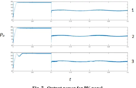
[image:5.612.329.559.146.295.2]In this work where P&O algorithm with a fuzzy logic control had been used, three Simulink modules were implemented. First module consists with a standard Perturb & Observe algorithm is implemented with a small duty cycle. The second module has the same algorithm with a quite big duty cycle. The third module fuzzy logic controller is made with P&O Algorithm. After the simulations were put to the test the next responses were obtained.
Fig. 7, Output power for PV panel.
Fig. 7 shows three plots for the output power of the PV panel. The third plot is the power output that used a standard P&O algorithm with a small duty cycle increment which gave quite a slow response. The second plot is the power output that uses the standard P&O algorithm with quite a large value for the duty cycle, there was a relatively fast response but large oscillations. The first plot shows the results obtained when the fuzzy logic controller was added to the standard P&O algorithm. It can be seen that the plot has a both quick response and a small power oscillations after the transients.
[image:5.612.335.554.518.647.2]It can be concluded that the third plot in Fig. 7 has a quick response, similar to the second plot but small power oscillations after transients similar to the first plot, which leads to a conclusion that this method gives both the fastest and most precise MPPT. Fig. 8 shows the oscillation of the first cycle for the three conditions.
International Journal of Emerging Technology and Advanced Engineering
Website: www.ijetae.com (ISSN 2250-2459, ISO 9001:2008 Certified Journal, Volume 7, Issue 5, May 2017)
17
[image:6.612.73.278.179.289.2]Fig. 9 shows exactly how the duty cycle increment changed during simulation so that previous responses are obtained.
Fig. 9, the changing of the duty cycle
V. CONCLUSION
The main purpose of this work was to compare MPPT techniques. The goal was to compare the response and power oscillation obtained in cases when the duty cycle is changed. A simulation has been carried out for the conventional P&O method with and without fuzzy logic control.
Comparing the results obtained it was found that combining fuzzy logic control with the P&O technique will give a better power oscillation (app. 50%). Adding fuzzy logic control to P&O results in both a quicker response and smaller power oscillations after transients.
This work shows that using fuzzy logic can improve the P&O method. Further research by adding fuzzy logic control to other commonly used MPPT techniques should lead to significant general improvements.
Acknowledgements
The author would like to thank Miroslav Dukic (Singidunum University) for his supervision and support while the work was prepared.
REFERENCES
[1] S. Mekhilef, R. Saidur and A. Safari. 2011. A review on solar energy use in industries. Renewable and sustainable Energy Reviews 15, 1777-1790.
[2] ParimitaMohanty,G.Bhuvaneswari , R.Balasubramanian , Navdeep Kaur Dhaliwal. 2014. MATLAB based modeling to study the performance of different MPPT techniques used for solar PV system under various operating conditions. Renewable and sustainable Energy Reviews 38, 581-593.
[3] UmaShankar Patel, Ms. DhaneshwariSahu, DeepkiranTirkey. 2013.Maximum Power Point Tracking Using Perturb & Observe Algorithm and Compare With another Algorithm. International Journal of Digital Application & Contemporary research ISSN: 2319-4863.
[4] Mohamed Azab. 2009. A New Maximum Power Point Tracking for Photovoltaic Systems. International Journal of Electrical and Electronics Engineering 3:11.
[5] PallaveeBhatnagar, R.K.Nema. 2013. Maximum power point tracking control techniques: State-of-the-art in photovoltaic applications. Renewable and sustainable Energy Reviews 23, 224-241.
[6] M.S. AïtCheikh, C. Larbes, G.F. TchoketchKebir and A. Zerguerras. 2007 .Maximum power point tracking using a fuzzy logic control scheme.Revue des Energies Renouvelables Vol. 10 N°3, 387 – 395. [7] Naoufel Khaldi, Hassan Mahmoudi, MalikaZazi, Youssef Barradi.
2014.Implementation of a MPPT Neural Controller for Photovoltaic Systems on FPGA Circuit.WSEAS TRANSACTIONS on POWER SYSTEMSVolume 9.
[8] Roberto Faranda, Sonia LEVA, Rob. Far., Son. Lev. 2008. Energy comparison of MPPT techniques for PV Systems.WSEAS TRANSACTIONS on POWER SYSTEMS, Issue 6, Volume 3, June.
[9] Hairul Nissah Zainudin & Saad Mekhilef ,Hai Zai,SaaMek. 2010. Comparison Study of Maximum Power Point Tracker Techniques for PV Systems. Proceedings of the 14th International Middle East Power Systems Conference (MEPCON’10), Cairo University, Egypt, December 19-21, Paper ID 278.
[10] R.K. Akikur, R. Saidur, H.W. Ping, K.R. Ullah. 2013. Comparative study of stand-alone and hybrid solar energy systems suitable for off-grid rural electrification: A review. Renewable and sustainable Energy Reviews 27, 738-752.
[11] Liqun Liu, XiaoliMeng, Chunxia Liu. 2016. A review of maximum power point tracking methods of PV power system at uniform and partial shading. Renewable and sustainable Energy Reviews 53, 1500-1507.
[12] M.S.Sivagamasundari1, Dr.P.MelbaMary,V.K.Velvizhi. 2013. Maximum Power Point Tracking For Photovoltaic System by Perturb and Observe Method Using Buck Boost Converter. International Journal of Advanced Research in Electrical, Electronics and Instrumentation Engineering Vol. 2, Issue 6.
![Fig. 2, Perturb & Observe method, [2].](https://thumb-us.123doks.com/thumbv2/123dok_us/8686545.876065/2.612.335.548.294.496/fig-perturb-observe-method.webp)
![Fig. 3, General diagram of a fuzzy controller, [6].](https://thumb-us.123doks.com/thumbv2/123dok_us/8686545.876065/3.612.48.258.186.401/fig-general-diagram-fuzzy-controller.webp)