International Journal of Emerging Technology and Advanced Engineering
Website: www.ijetae.com (ISSN 2250-2459,ISO 9001:2008 Certified Journal, Volume 5, Issue 12, December 2015)
173
Intelligent Energy Saving System
Cedric Sean OKINDA
1,
Innocent NYALALA
2, Zhang CHI
3,
Shen MINGXIA
4 1,3,4College of Engineering, Nanjing Agricultural University, Nanjing 210095, P.R.China;2College of Information Science and Technology, Nanjing Agricultural University, Nanjing 210095, P.R. China;
Abstract— An intelligent energy-saving system is of utmost importance in areas where lighting and air conditioning are crucial. This paper introduces a robust phenomenon of voltage optimization by auto-phase angle control for lighting by zero crossing detection (ZCD), precision in temperature regulation and detection. Three sensors are used Human Presence Detector Sensor, Light Dependant Resistor (LDR) and a temperature sensor. The control unit consists of a microcontroller unit, whose output controls the actuators, i.e. lamps and fans via a relay drive and an optoisolator respectively. This study applies an infrared detection mechanism as the initialization point of the proposed system, a threshold of lux level is benchmarked with reference to daylight and the reference optimum lighting comfort-ability level. A novel method for voltage optimization was introduced by phase angle delay mechanism by a Zero Crossing Detector. For further energy saving capability the proposed system synchronized the fans relay drive with the air conditioner to prevent simultaneous running. An additional add-on LCD was set up to ease monitoring the occupied reading compartments and temperature display. The proposed system was tested in a modern library set-up and successfully saved an average of 30.06% power consumption and proved to be reliable and safe.
Keywords— Illumination, lux, microcontroller, phase angle, voltage optimization, zero crossing detection.
I. INTRODUCTION
Currently, the building sector consumes about one-third of the total global energy, and a substantial amount of this consumption is directly cognate to HVAC systems (Homod, Sahari et al. 2014). Thus, the building sector bears a significant responsibility for matching between demand and energy supply and thus a desideratum to preserve energy arises (Sakulpipatsin, Itard et al. 2010, Sovacool 2010). Energy preservation in the building sector can be achieved by two ways; namely by ameliorating the efficiency of sundry contrivances such as illumination and HVAC systems, and/or by reducing the building loads utilizing natural ventilation and shadings. However, it was found that energy preserving contributions due to optimal controls of shadings is frivolous compared to natural ventilation by (Xu, Jia et al. , Xiaoyan, Qingshan et al. 2011).
It has been reported that natural ventilation in buildings functions best in warm summer areas, such as Europe (Roth, Dieckmann et al. 2006). In more astringent climates, such as warm and humid regions omitting some coastal region, research has shown that pristinely natural ventilation systems are not sufficient to sustain acceptable thermal comfort (Emmerich 2006, Zhai, Johnson et al. 2011). A study on the integration of natural ventilation into the HVAC systems operation of indoor thermal control showed an achievement of a reduction in energy consumptions in warmer climates, such as humid sub-tropical (Axley 2001), sub-tropical (Haase and Amato 2009), and arid (Ezzeldin, Rees, et al. 2009).
Other studies have been done on daylight factors produced inside a room for different models of Windows (Acosta, Munoz et al. 2015), semi-transparent solar cells for windows (Miyazaki, Akisawa et al. 2005), load sharing between the two different building (Cho, Lee et al. 2013), potential of daylighting in reducing electrical lighting load (Singh and Garg 2010).
International Journal of Emerging Technology and Advanced Engineering
Website: www.ijetae.com (ISSN 2250-2459,ISO 9001:2008 Certified Journal, Volume 5, Issue 12, December 2015)
174
This study was conducted in a modern library system where illumination and temperature control is of adverse importance as lighting has to be kept at an optimum level and temperature likewise without use of evaporative coolers that would lead to formation of moist and froth on the books
A prototype system was developed and implemented with the main objective being: To achieve an efficient, reliable and a safe system that can save energy. Other goals are: To maximize the use of daylighting and automatic balancing of electric lighting with natural lighting, to come up with a single unit for illumination and HVAC systems monitoring.
II. MATERIALS AND METHODS
A. Development Designs and Documentation Overview 1. Overview:
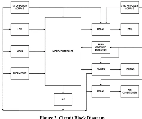
The proposed system consist of four units Sensor unit, Zero crossing detection unit, Controller unit, and Actuator unit (fig 1). The sensor unit consists of Human Presence Detector (MEMS D6T from OMRON), Light Dependent Resistor (LDR from Sunrom Technologies) and thermistor (LM35 from Texas Instruments) for the body, lux, and temperature detection respectively. The Zero Crossing Detector unit consist of the ZCD composed of 2 diodes, resistor, and a capacitor to transform the 240V AC sine wave to 5V AC square wave. Control unit consists of the microcontroller Arduino Uno from ARDUINO. Actuator unit consists of the controlled devices (lamp, fan, and air conditioner), two relay drives (1 pole 5A slim type from Fujitsu) and an optoisolator/ dimmer (MOC 3021 from Motorola).
Fig.1.The structure of the Intelligent Energy-saving system.
The working process of the Intelligent Energy-saving system is described as the following:
a.Human Body Detection
When a reader comes to the field of view of MEMS (Microelectromechanical systems) non-contact thermal sensors the infrared energy radiated from target objects is converted to heat energy by MEMS thermopiles hence it uses this technique to measure temperature. MEMS have the ability to detect the stationary human presence and also determine the number of people hence was used in this study. The direct connection method was used to interface with the microcontroller with two pull up resistors or 5k ohms each.
b.Lux level and temperature determination
After a human presence is detected, daylight lux level is determined by the LDR, which is a light-controlled variable resistor, exhibiting photoconductivity. The lux threshold for Illumination was calculated by equation (1).
Where
I = illumination (lux, lumen/m2), Li = lumens per lamp (lumen), Cu = coefficient of utilization, LLF = light loss factor, Ai = area per lamp (m2)
The daylight flux level is compared to the threshold lux if it is less than the table lamp is dimmed to sufficient levels by the dimmer so that the resultant optimum threshold lux level is achieved.
The process of lux and temperature determination occurs concurrently, temperature levels were sensed by a thermistor, the relation between resistance and temperature is constant for first order approximation in thermistors Equation (2).
(
)
Where
= change in temperature, K = first-order temperature
coefficient of resistance,
= change in temperature
International Journal of Emerging Technology and Advanced Engineering
Website: www.ijetae.com (ISSN 2250-2459,ISO 9001:2008 Certified Journal, Volume 5, Issue 12, December 2015)
175
A basic Centigrade Temperature Sensor configuration was used for LM35 to give an output of 10.0mV per 0 C. temperature values were displayed on an LCD at the librarian’s desk together with the number of people in each reading compartment
c. Table lamp dimming
The table lamp dimming is only done only if the daylighting does not meet the set threshold lux level. The dimmer is an optoisolator that we used to achieve our objective of voltage optimization by phase angle delay by the following process.
1. Zero Crossing Detection
The zero crossing of supply AC source (sine wave) is determined so to establish the initial delay point by the dimmer (phase angle delay). 240 V AC sine wave is the ZCD input, and its output is a 5V AC square wave that act as an interrupt to the controller.
2. Setting of the delay
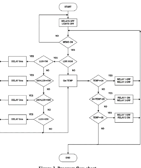
The delay is set by the microcontroller with reference to lux level less than the threshold iteratively.
If
set delay to 8 ms
If
set delay to 6 ms
If
set delay to 3 ms
If
set delay to 0 ms
3. Light dimming
This optoisolator was used to drive the load directly and was interfaced with two resistors, a capacitor, a triac and resistor and capacitor to snub the triac and a coupler respectively. The input signal from the microcontroller with reference to ZCD determines the delay of the phase angle.
d. Temperature control
Sensed temperature levels were used to control the ventilation mechanisms (fan and air conditioner), according to equation (3).
If set all relays OFF If set fan relay ON
If set fan relay OFF, A.C. relay ON
This is to prevent the fan and A.C. from running simultaneously and having the pre-set temperature of the
A.C. at 280C. This gave an allowance for more power
saving achievements.
e. Repeat the step 1 till five again
[image:3.612.321.563.251.453.2]The Circuit design and interfacing was done according to the block diagram in Figure 2.
Figure 2. Circuit Block Diagram
The project was designed and implemented using ATMEG 16A of the AVR family of the microcontroller. It is a complete microcontroller with 40 PINs needed by the four bidirectional ports. An 8-bit single chip with powerful
CPU optimized for control applications. The
microcontroller circuit design was attained from the specific components output parameters and the microcontroller electrical specifications. This project had three analog inputs and three outputs; standard design applied to the RESET, AVCC, and AREF pins.
International Journal of Emerging Technology and Advanced Engineering
Website: www.ijetae.com (ISSN 2250-2459,ISO 9001:2008 Certified Journal, Volume 5, Issue 12, December 2015)
[image:4.612.319.556.108.305.2]176
Figure 3. Program flow chart
III. EXPERIMENTALS RESULTS AND DISSCUSION A. Design Simulation
The complete circuit was drawn and simulated in the Proteus Design suit 8.1 ISIS schematic capture. Our main observation were made on the ZCD, Dimmer, and the LCD so as to determine if our objectives can be achieved.
B. LCD simulation results
The MEMS was represented by an interactive potentiometer, when its output went HIGHT, it signifies presence of a person at a reading table, and similarly at another reading table within the same compartment, thus the proposed system could establish the number of people in a given compartment at a specific time and display the compartments name and number of people inside on an LCD. Temperature display was also achieved, by altering the interactive thermistor (LM35) the variations were depicted on the display.
C. ZCD simulation results
In this simulation, we used a sine wave generator of 50Hz 480V peak to peak as the input signal. An interactive oscilloscope was used to measure and display the input and the output voltage and waveforms as in Figure 4.
Fig 4.ZCD input and output waveforms
The measured input value was 480V peak to peak while the output was at 10V peak to peak, tis outcome showed that the circuit designed and setup was indeed a ZCD
D. Dimmer simulation results
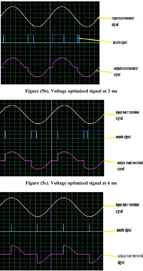
The objective of the dimmer was to achieve voltage optimization at different illumination levels. Illumination levels were achieved by similarly altering the interactive LDR so as to vary its output, the dimmer being an optoisolator was connected to the sine wave generator of 50Hz 480V peak to peak as the input signal (same as ZCD input) then its output to an interactive lamp. When the LCD was varied, the input signal was also delayed according to the set program prescriptions, Figure (5). The observations were made on the oscilloscope to determine the waveforms at the dimmer two main terminals and the anode nodes At below 250 lux, there was no delay the two main terminals had identical waveforms.
[image:4.612.51.296.129.422.2] [image:4.612.326.569.521.666.2]International Journal of Emerging Technology and Advanced Engineering
Website: www.ijetae.com (ISSN 2250-2459,ISO 9001:2008 Certified Journal, Volume 5, Issue 12, December 2015)
177
There is no voltage optimization because the illumination is very low thus the reading lamp lights brightest to achieve the lux threshold level.
At a lux level of 300 a delay was observed to set in as below in Figure (5b).
It was observed that the more the lux level rises, the more the delay time thus our objective of voltage optimization was achieved by the simulated results as in Figure (5c) and Figure (5d).
Figure (5b). Voltage optimized signal at 3 ms
Figure (5c). Voltage optimized signal at 6 ms
Figure (5d). Voltage optimized signal at 8 ms
E. Temperature controls simulation results
The simulated circuit exhibited stability in temperature control, variation of the interactive thermistor had a true value display on the LCD, and the relays i.e. relay 1 (fan drive) and relay 2 (A.C. drive) never went ON at the same time with different variations of temperature hence achieved our objective of prevention of simultaneous running of A.C. and fan.
F. Prototype Implementation
The prototype testing was conducted in a single library room space compartment (3m×4m×3m) with two reading table, six ceiling fluorescence lamps (30 Watts) and two reading lamp (32 Watts) as in Figure 1.
The system displayed accuracy, stability, reliability and safety in; temperature determination, display and regulation by the fan or A.C. but not both as by the objective, illumination control by voltage optimization was also achieved the reading lamp was observed to dim at different daylight lux levels thus voltage optimization objective was achieved, the human detection sensor proofed to be more efficient and reliable as it could not only detect a human present at a reading table but also determine the number of people inside a reading compartment.
To determine that this prototype can be an enhanced intelligent energy saving system it was tested at a library compartment and previous daily meter readings (power) for 30 days before installation of the prototype system and 30 days when the prototype system was installed.
[image:5.612.52.548.232.691.2]The data for the 30 days were analyzed as below in Figure 6.
[image:5.612.50.287.242.690.2] [image:5.612.321.566.498.651.2]International Journal of Emerging Technology and Advanced Engineering
Website: www.ijetae.com (ISSN 2250-2459,ISO 9001:2008 Certified Journal, Volume 5, Issue 12, December 2015)
178
The power trend before the prototype installation has a steep gradient showing high usage of power at a constant rate (red curve) while that for the prototype deployment period is gradual gradient (green curve) hence lower power consumptions. This shows that over the same period the power consumption with the prototype installed is lower hence energy saving objective is achieved. In the power consumption graph in Figure 7, it is more evident that the prototype resulted in lowering power consumption at the equal length of time.
Figure 7: Comparisons of Energy Consumptions
In the data analysis as in the table below, Table 1.
Energy Consumption Data
Power Consumption
Before Prototype
During Prototype
Total Consumption (30 days)
12460 8715
Average Daily Power Consumption
415.3333 290.5
The average daily power saved was found to be 124.8333 KWh making a percentage of 30.06% of energy saved. From the data analysis, it shows that the proposed system achieved all the set objectives, and aim hence can be used for energy saving in a typical modern library.
IV. CONCLUSION
This paper presents the research work in daylighting and the approaches for estimating daylight and lighting energy savings.
The system applies a robust phenomenon of voltage optimization by auto-phase angle control for lighting by zero crossing detection and precision in temperature regulation. The aspects and technologies including data measurements, voltage regulation mechanism development, and daylight-linked lighting controls were achieved completely.
In our analysis, we found that the system is indeed energy saving by reducing energy consumption to about 30.06% that is very effective in the long run once initial costs are recovered. To augment the sufficiency of the system, a single controller can be utilized to control several tables, and it is only limited by the Port PIN number of the microcontroller. A further development of the system can allow the user to pre-set temperature values or to determine which bulb should be activated by the controls.
This system is not constrained to use the library system alone hence there is further scope for enhancement for improvement on intelligent systems This system is not constrained to use the library system alone hence there is further scope for enhancement for improvement on intelligent systems
REFERENCES
[1] Acosta, I., et al. (2015). "Analysis of daylight factors and energy saving allowed by windows under overcast sky conditions." Renewable Energy 77: 194-207.
[2] Axley, J. W. (2001). "Application of Natural Ventilation for US Commercial Buildings–Climate Suitability, Design Strategies & Methods, Modeling Studies." Gaithersburg, MD, NIST.
[3] Cho, S., et al. (2013). "Energy simulation modeling and savings analysis of load sharing between house and office." Renewable Energy 54: 70-77.
[4] Dennis, A. K. (2013). Raspberry Pi home automation with Arduino, Packt Publishing Ltd.
[5] Emmerich, S. J. (2006). "Simulated performance of natural and hybrid ventilation systems in an office building." Hvac&R Research 12(4): 975-1004.
[6] Ezzeldin, S., et al. (2009). Performance of mixed-mode cooling strategies for office buildings in arid climates. Proceedings of the 11th International IBPSA Conference, Glasgow, Scotland.
[7] Haase, M. and A. Amato (2009). "An investigation of the potential for natural ventilation and building orientation to achieve thermal comfort in warm and humid climates." Solar Energy 83(3): 389-399. [8] Homod, R. Z., et al. (2014). "Energy saving by integrated control of
natural ventilation and HVAC systems using model guide for comparison." Renewable Energy 71: 639-650.
[9] Miorandi, D., et al. (2012). "Internet of things: Vision, applications and research challenges." Ad Hoc Networks 10(7): 1497-1516. [10] Miyazaki, T., et al. (2005). "Energy savings of office buildings by
the use of semi-transparent solar cells for windows." Renewable Energy 30(3): 281-304.
International Journal of Emerging Technology and Advanced Engineering
Website: www.ijetae.com (ISSN 2250-2459,ISO 9001:2008 Certified Journal, Volume 5, Issue 12, December 2015)
179
[12] Sakulpipatsin, P., et al. (2010). "An energy application for analysisof buildings and HVAC systems." Energy and Buildings 42(1): 90-99.
[13] Singh, M. C. and S. N. Garg (2010). "Illuminance estimation and daylighting energy savings for Indian regions." Renewable Energy 35(3): 703-711.
[14] Sovacool, B. K. (2010). The Routledge handbook of energy security, Routledge.
[15] Vujović, V. and M. Maksimović (2015). "Raspberry Pi as a Sensor Web node for home automation." Computers & Electrical Engineering 44: 153-171.
[16] Xiaoyan, X., et al. (2011). Analysis of energy saving potential using shadings and natural ventilation in four major cities in China. Control Conference (CCC), 2011 30th Chinese, IEEE.
[17] Xu, X., et al. Analysis of Energy Saving Potential using Shadings and Natural Ventilation in Four Major Cities in China. Proceedings of the 30th Chinese Control Conference.