Non-Linear Synthesis Problems for Plane Radiating
Systems According to the Prescribed Power Directivity
Pattern
Mykhaylo Andriychuk*, Petro Savenko, Myroslava Tkach
Pidstryhach Institute for Applied Problems in Mechanics and Mathematics, NASU, Lviv, Ukraine. Email: *[email protected], [email protected], [email protected]
Received August 1st, 2013; revised September 1st, 2013; accepted September 10th, 2013
Copyright © 2013 Mykhaylo Andriychuk et al. This is an open access article distributed under the Creative Commons Attribution License, which permits unrestricted use, distribution, and reproduction in any medium, provided the original work is properly cited.
ABSTRACT
A variational formulation of the synthesis problem for plane radiating systems according to the prescribed power direc- tivity pattern (DP) is considered. The function representing the mean-square deviation of the prescribed and synthe- sized power DPs and containing the additional term with squared norm of the current or field in the antenna aperture is considered as the criterion of optimization. Freedom to choose the phase DP is used to improve the proximity of the prescribed and synthesized DPs. In such formulation, the classes of non-linear problems, for which the non-uniqueness of solutions, their branching and bifurcation are characteristic, arise. The properties of solutions depend on the electric size of radiating system and prescribed power DP. From a practical point of view, the existence of different solutions creating the same or similar DPs, gives the opportunity to choose the solution that has a simpler implementation. The synthesis problems for plane radiating systems and plane arrays are considered.
Keywords: Power Radiation Pattern; Synthesis Problem; Non-Linear Equation; Bifurcation of Solutions; Numerical
Modeling
1. Introduction
Increasing requirements to the modern radiating systems promote to further evolution of classical antenna synthe- sis theory [1-6] and development of new methods [7-11] in order to take into account a series of stringent re- quirements to control of the antenna directivity charac- teristics [12-14], consideration of the mutual coupling of radiators [15], noise-immunity [16] etc.
In many practical applications at the design stage of antennas and arrays the requirements are imposed only to the power DP [17,18]. At that, the freedom of choice among the phase DPs is used for improvement of the approximation quality of the synthesized DP’s squared module to the prescribed power DP. Appearing at that a necessity to approximate the real positive function (pre- scribed power DP) by square of module of the complex valued function generates the classes of the non-linear synthesis problems. Non-uniqueness and bifurcation of solutions are the characteristic feature of such problems. From the practical point of view, the existence of several
types of solutions, which create the same or close power DPs, gives a possibility to choose that solution, which has simpler realization.
The problems of quantity and properties of the existing solutions using the methods of non-linear analysis [19] were investigated partially for the synthesis problems of linear antenna arrays in [10,11,15,18,20,21]. It was shown that the non-uniqueness and branching of solu- tions are the characteristics for these problems in the both cases if the mutual coupling of separate radiators of array is not being taken into account, and by being taken into account of such coupling. The properties of existing so-lutions depend on the value of physical parameters of array and properties of the prescribed power DP.
Investigation of solutions of the nonlinear synthesis problems for plane radiating systems substantively dif- fers from such investigation of the synthesis problems for linear antennas and arrays. In particular, unlike the exist- ing the branching points for the synthesis problems of linear antenna and arrays, the lines of branching of the solutions appear in the synthesis problems for the plane antenna systems. The problem to search these lines is
insufficiently investigated two-parameter non-linear spec- tral problem [22].
In the proposed work, the variational statement of the synthesis problems for the plane radiating systems ac- cording to the prescribed power DP is examined. These problems are reduced to the investigation and numerical solution of the non-linear integral equations of Hammer- stein’s type. The kernel of these equations contains two physical parameters, which describe the geometry of radiating aperture and region where the prescribed power DP is given.
The method for search of the bifurcation lines of the optimal solutions is developed; the justified algorithms to determine the optimal solutions of the synthesis problems and to search the existing solutions of various types for the synthesis equations are elaborated. It is shown that freedom in choosing the obtained optimal phase DP im- proves the quality of approximation of the synthesized DP to the prescribed one considerably, as compared with the synthesis in the class of the cophased DPs. In par- ticular, this allows in some cases to decrease the dimen- sions of radiating system up to 30%, as compared with the synthesis in the class of cophased DPs, remaining the effectiveness of the synthesis the same.
2. Statement of Problem
The statement of the synthesis problem according to the prescribed power DP is used in many practical applica- tions [1,5,8]. In spite of fact that the power DP N can be
easy obtained from the amplitude DP f : (N f 2),
and vice versa, the synthesis problems of the given am-
plitude DP F0 and the given power DP are the
different problems. For example, if
2
0 0
N F
*
f is optimal solu- tion for some variational synthesis problem according to the amplitude DP F then f*2 will not be optimal solu-
tion of the analogous problem according to the pre- scribed power DP N0.
In general case the calculation of the DP f of antenna
by the currents (fields) I in the antenna aperture is real-
ized by action of some linear bounded operator A [11]
f AI . (1) The functions f and I can be either the vectors if the
vector character of electromagnetic field is taking into account in the process of statement and solving the syn- thesis problem, or scalar functions if some simplifica- tions for antenna are applicable.
The specific forms of operator A, functions f and I will
be presented below in the process of solving the synthe- sis problems for the investigated radiating systems. We demonstrate here the peculiarities of the synthesis prob- lem according to the prescribed power DP N0 on example
of a plane continuous aperture.
Introducing the specific generalized coordinate system
[6] we pass from the vectorial statement of the synthesis problem to two scalar problems. Separation of the - and
-components of the DP and current’s (field’s) compo-
nents in the antenna elements is assumed too. We con- sider below the scalar synthesis problems for plane radi- ating apertures and arrays.
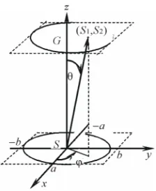
The geometry of synthesis problem for plane rectan-
gular aperture is shown in Figure 1. The DP of plane
aperture is determined by formula [3]
1 1 2 21, 2 ,
i c xs c ys
S
d d
f s s AI
I x y e x y, (2)where
1 sin cos sin ,
s 1 (3)
2 sin sin sin
s 2 (4) are the generalized dimensionless coordinates that allows to consider the synthesis problem in two relatively-per- pendicular planes independently [1,6]. The parameters
1 sin
c ka 1, (5)
2 sin
c kb 2 (6)
describe electrical size of antenna; a, b are the geometri-
cal parameters of aperture; 1, 2 are the angles char-
acterizing the domain where DP N0 is prescribed (N0 = 0
outside 1 and 2); k 2 is wave number.
Use of generalized parameters c1 and c2 allows to con-
sider the synthesis problem in wide region of frequencies, including the submm, mm, cm and longer lengths of the EM field’s waves.
The variational formulation of the synthesis problem consists in minimization of functional
2 2
0 1 2 1 2 1 2
2
, , d
, d d .
G
S
d
I N s s f s s s s
I x y x y
(7) [image:2.595.368.480.573.710.2]The respective Euler’s equation relative to optimal current distribution I is given by
1 1 2 22 1 2
0 1 2 1 2
2
1 2 1 2
, ,
2 2
, d d ,
G
i c xs c ys
c c
I x y N s s AI s s
AI s s e s s
,(8)
and respective equation for the DP f has form
2
1 2 0 1 2 1 2
1 2 1 2 1 2 1 2 1 2
2
, , ,
, , , ; , , d d .
G
f s s B f N s s f s s
K s s s s c c f s s s s
(9) The kernel K s s s s c c
1, , , ; ,2 1 2 1 2 in the general case is expressed as
1 2 1 2 1 2
1 2
1 1 1 2 2 2
2
, , , ; ,
exp d d
2 G
K s s s s c c c c
i c x s s c y s s x y
(10)and depends essentially on the form of aperture. For the rectangular aperture (10) has form
1
1
1
2
2
2
1 2 1 2 1 2
1 1 2 2
sin sin
, , , ; , .(11)
π π
c s s c s s
K s s s s c c
s s s s
If the optimal solution f* to (9) is found, then opti-
mal distribution of current is determined by formula
1 1 2 22 1 2
* 2 0 1 2 *
* 1 2 1 2
, ( , ) (
2 π
, d d .
G
i c xs c ys
c c
I x y N s s f s s
f s s e s s
1, )2(12)
Numerical solving Equation (9) is simpler than solving Equation (8), therefore we use below in the process of solving the specific synthesis problems solution to Equa- tion (9) and determine the optimal current distribution
*
I by formula (12).
3. Determination of Bifurcation Lines:
Case of the Plane Rectangular Aperture
The non-linear Equation (9) has only zero solution at small values of parameters c1 and c2 which contain in thekernel (11). The non-zero solutions appear, namely the bifurcation of solutions occurs, if c1 and c2 increase. The
bifurcated solutions have the different properties de- pending on the form of the prescribed power DP N0, val-
ues c1 and c2. For one’s turn, these solutions correspond
to the different optimal current distributions I*, calcu- lated by (12). Of course, the different sets of functions
* and *
f I give the different values of functional .
In this connection, investigation of the branching process, search of different solutions, and determination of those provide the minimal value of is of practical interest.
Accordingly to the theory of branching the solutions [23], the bifurcation points of solutions to (9) are deter- mined using the next linear equation
1 2 0 1 2 1 2 1 2 1 2
1 2 1 2
2
, , , , ,
, d d .
G
; ,
f s s N s s K s s s s c c
f s s s s
(13)On the other hand, this equation can be considered as the non-linear two-parameter spectral problem. We use the method of implicit function proposed in [22] for de- termination of values of the parameters c1 and c2 at which
(13) has non-zero solutions. The non-zero solutions ori- ginate at the values c1 and c2, for which except the evi-
dent eigen value 1 1, the other eigen values i 1
of Equation (13) appear.
Using the cubature formulas we obtain on the basis of (13) the homogeneous linear algebraic system (LAS) of
P-th order for determination of eigenfunctions and cor-
responding eigenvalues
1 2 0
1 1
1 2
,
, , , , , 1 .
P P
in P jm jm
j m
in jm jm
x A c c a N Q
K Q Q c c x i n P
x x (14)Here the number P corresponds to quantity of discre-
tization points. In Equation (14) ,
is vector of unknowns eigenfunctions,
1 , 2
jm jm
jm
Q s s
jm
a are the coef-
ficients of cubature formula.
In order LAS (14) has different from zero solutions, it is necessary that parameters c1 and c2 be the solutions of
equation
1, 2
det
1, 2
P c c AP c c IP 0
, (15)
where IP is unit matrix.
According to the method of implicit functions, search of solutions to (15) is reduced to the next Cauchy prob- lem
1 2
12
1 1 2
, ,
P P
c c c
dc
dc c c c2
, (16)
2 1 2 , 1, 2,3,
c c c (17)
Initial conditions (17) are determined by solving the auxiliary non-linear one-parameter spectral problem on the beam c2c1 in (15). As result, we receive the
next equation for finding the zeros of determinant
1 det
( ,1 1)
0P c A cP c IP
, (18)
which are determined by some known method, for ex- ample, by the bisection method.
Consequently, solving the Cauchy problem, we obtain a set of bifurcation points of the solution to (9). As the matrix of (15) is analytical function of parameters c1 and
c2, the respective curves, which describe the spectrum’s
Note that eigenfunctions of the problem (14), which correspond to bifurcation points, describe the properties of solutions of the initial Equation (9) in the first ap- proximation.
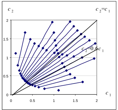
We consider the results related to determination of the bifurcation lines for the synthesis problem of plane aper- ture at the prescribed power DP N0
s s1, 2
1c
. The bi- furcation points, obtained as the result of solving the auxiliary one-dimensional spectral problem (18) on the beams c2 1
c
1
c
, are shown in Figure 2. The obtained
sets of values ( ) are the initial conditions (17) for
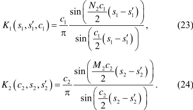
the Cauchy problem (16). The first four curves, obtained in the process of solving the problem (16)-(17), are pre-
sented in Figure 3. The both Runge-Kutta and Adams
methods were used to obtain the numerical solution. The
initial values ( ), which were chosen on the beam
, are indicated by small circles.
0 0
1, 2
c c
0 0
1,c2
2 0.6
c
0 0.5 1 1.5 2
0 0.5 1 1.5 2
c2 c2=c1
[image:4.595.71.274.299.489.2]c1 c2=0.6c1
Figure 2. The bifurcation points on the beams c2 βc1 for plane aperture.
0 0.5 1 1.5 2
0 0.5 1 1.5 2
c2
c1 c2=c1
[image:4.595.83.262.533.706.2]c2=0.6c1
Figure 3. The bifurcation lines in the plane (c1,c2) for plane aperture.
The eigenfunctions of LAS (14) are used in the proc- ess of construction of the bifurcated solutions of the non- linear Equation (9), which branch off the zero solution. The properties of bifurcated solutions depend on the properties of symmetry (parity) of the prescribed DP N0
and on the properties of eigenfunctions. In the process of construction of the bifurcated solutions one should take into account that the properties of the eigenfunctions differ for the various set of parameters c1 and c2 in the
plane c Oc1 2.
4. Features of Statement for Specific
Radiating Systems
4.1. Elliptic Aperture
The synthesis problem for an elliptic aperture is reduced to minimization of functional (7), and the respective Eu-ler’s equation for determination of optimal current in the aperture is determined by formula similar to (8). By this, integration is carried out over the elliptic domain of the antenna aperture.
The aperture DP is determined by formula similar to (2). The kernel (10) for elliptic aperture is given by
1 2 2
1 2 1 2 1 2 1 1 1
1
2 2 2 2
2 2 2
, , , ; , ; , 2 cos
sin 1
d ,
K s s s s c c a b a b c x s s
c s s x x c s s
(19) where a and b are semiaxes of ellipse. The optimal cur-
rent is determined by the DP f* found from (9) as fol-
lows
1 1 2 22 1 2
0 1 2 1 2
1 2 1 2
2
, ,
, d d .
G
i c xs c ys
c c
I x y ab N s s f s s
f s s e s s
,
(20)
The numerical results of synthesis for specific pre- scribed power DPs N0 will be given in Subsection 5.2.
4.2. Plane Equidistant Rectangular Array, Bifurcation of Solutions
In the case of scalar consideration of the synthesis prob- lem one can restrict by the following representation for DP (array multiplier)
1 1 2 21, 2
N M
i c ns c ms nm
n N m M
f s s AI I e
, (21)where N2M2
2N 1
2M 1
sin cos / sins
is number of ra-
diators; 1 1 , s2sin sin / sin 2
sin
c kd
are the generalized angular coordinates; 1 1 1,
2 d2sin 2
are the distances between radiators along the and
axes, respectively; 1
Ox
Oy and 2 are the angles
where the DP N0
s s1, 2
is given (N0
s s1, 2
0 out- side these angles).
1, 2
f s s is c1
Function 2 -periodical relative to
1
s and 2 c2-periodical relative to s2. In this connec- tion, one can consider the synthesis problem for such array within the limits of one period.
The minimizing functional has form similar to (7), the Euler’s equation for the optimal currents I and DP f are
determined by formulas similar to (8) and (9), respec- tively.
The kernel K is degenerated and it is presented as the
product of two independent functions
1, ,2 2
1
2
2, 2, 2
Figure 4. The bifurcation points in the plane for rectangular array.
1 2
(c ,c )
1, , ,2 1 1 1, ,1
K c c s s s s c s
K s K c s s , (22)
lines obtained by solving the Cauchy problem (16) with the initial values (17) are presented in Figure 5. Simi-
larly to the case of rectangular plane aperture, the bifur-
cation lines are symmetrical relatively the axes 1,
2, and intersection of the curves corresponding to the second and third eigenvalues is observed.
Oc Oc where
2 1 11 1 1 1
1 2 , , 2 N c 1 1 1 1 sin sin s s c K s s c
c
s s
, (23)
4.3. Plane Hexagonal Array, Bifurcation of Solutions
2 2 2 2 22 2 2 2
2 2 2 2 , , 2 M c sin sin s s c
K c s s
c s s
. (24)
The DP of hexagonal array has the form similar to (21):
1 1 2 2( ) 1 2
( )
, N M n i c ns c ms
nm n N m M n
f s s AI I e
. (26)The investigation of solution to respective Euler’s eq-uations is carried out in the manner similar to the case of
plane aperture. If the optimal DP f* by solving equa-
tion type of (9) is found, the optimal current distribution
*
I is given by
1 1 *
i c js 2 2 2
1 2
* 2 2 0 * d d1 2
, . c ls jl c c , I
The number of linear subarrays along the axes
(coordinate 2
Oy
s ) is odd, and number of radiators in the
central linear subarray along the axes (coordinate
1
Ox
s ) is odd too. For such array’s geometry, the kernel of integral Equation (9) can be written in form (27).
N f f
j N N l M M
e s s
0 1 s2
In the case when the above assumption regarding the number of radiators in the subarrays does not satisfied, (27) has more complicate form.
(25)
The numerical results for rectangular array are pre- sented for the problems of determination of the bifurca- tion lines for the array consisting of N2 × M2 = 11 × 11
radiators for the prescribed power DP N s,
1,0.5
Search of bifurcation lines for the solutions to nonlin- ear Equation (9) is carried out for array consisting of 61 radiators for the prescribed power DP N0
s s1, 2
1 inthe region c
1 2
.0, 0c22.0
atthe various values of parameter 1
, : 0 2
c c c
in functional (7). In the first stage, the one-dimensional auxiliary problems is solved on the beams c2c1. The bifurcation points in
c
. In Figure 4 the bifurcation points on the beams 2c1, received by solving the series of auxiliary
one-parameter problems, are shown. The bifurcation
1 sin sin cos M n c M
( )1 1 1
1 2 1 1 2 2 2 2
1
1 1 1
1 1 1
1 1 1
1 1 1
sin 0 0.5
, , , , 2 cos
0.5
sin ( ) 0.5
, is odd,
0.5
2 0.5 , is even.
M n m n s s 2,
c c s s mc s s
c s s c M n s s
M n c s s
c n s s M n
[image:5.595.327.517.84.232.2] [image:5.595.89.287.298.411.2]the respective beams are presented in Figure 6. The
points ( ( ) ( )), for which eigen values 1i , 2i
c c ( )i 1 deter-
mined approximately from plot data in this stage.
In the second stage, the specification of the values
( ) by solving the transcendental equation type of
(18) is carried out. The points ( ) considered as
initial approximations in this procedure. The bijection method is used for this goal. In the third finish stage after
the specifications of the values ( ), the bifurcation
lines in the plane ( 1 2) are determined by solving
Chauchy problem (16)-(17). In Figure 7, the curves cor-
responding to the first four eigenvalues ( ) ( )
1i , 2i
c c
( ) ( ) 1i , 2i
c c
( ) ( ) 1i , 2i
c c
,
c c
( )i 1
are
shown. Similarly to previous investigations, the cross section of curves corresponding to the second and third eigenvalues is observed.
[image:6.595.326.515.89.237.2]Note that the problem of specification of the roots of Equation (18), as well as correct solving the Cauchy problem (16)-(17) are quite complicate computational problems, because they require for their solving a series of computational experiments with the various initial approximations.
Figure 5. The bifurcation lines in the plane for rec- tangular array.
1 2
(c ,c )
Figure 6. The bifurcation points in the plane for hexagonal array.
1 2
(c ,c
Figure 7. The bifurcation lines in the plane for he- xagonal array.
1 2
(c ,c )
5. Computational Results of Synthesis
The results of numerical calculations are presented for the synthesis problems of several prescribed power DPs. We use the iterative process [24]
1 1 ( ), 0,1, 2,
n n n
f f B f n
(28)for numerical solution of (9). Parameter
0, 1 is used for convergence acceleration of (28).The numerical results demonstrate that for the certain ranges of the physical parameters of antennas there exist different types of solutions to (9). These solutions pro- vide different degree of approximation of the synthesized power DP to the prescribed one. The investigations which show the dependence of the mean square deviation of the DP on the type of parity of the prescribed initial approximations are carried out for the various types of the considered antennas.
In the process of numerical calculations one substanti-
ated that for the prescribed power DP with
two axes of symmetry, there exist the solutions of dif- ferent types of parity relative to the coordinates 1
0 1, 2
N s s
s and
2
s . It is ascertained that for this case there exist various
types of solutions to (9) with the next properties of the phase of synthesized DP, namely function argf s s
1, 2
:1) even relatively s1 and s2;
2) even relatively s1 and odd relatively s2; 3) odd relatively s1 and even relatively s2; 4) odd relatively s1 and s2.
In order to obtain these solutions, one should to give initial approximation of the respective type for (28).
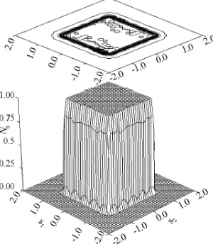
5.1. Plane Rectangular Aperture
The computational results related to solving the synthesis problem of plane rectangular aperture are shown at the
prescribed power DP N0 1 (Figure 8). The problem
is reduced to solving the non-linear Equation (11) by the successive approximation method (28). In order to obtain
[image:6.595.72.275.349.505.2] [image:6.595.73.274.549.709.2]the different types of solutions, the initial approximations of type 1) - 4) were chosen for the iterative process (28).
The synthesized power DP f 2 and phase DP arg f are
shown in Figures 9 and 10 at 1 , 2 .
One can see that the phase DP arg f presented in Fig- ure 10 is even relative to 1
8.0
c c 8.0
s and odd relative to s2.
This indicates that phase DP arg f has the same parity
properties that the eigenfunction which corresponds to the eigenvalue 2 in
Figure 3 (curve corresponds to
this value of 2 crosses the beam
2 1 in the
point 1 , 2 ). Optimal current distribu-
tion
0.6
c c
1.2
c 4 c 0.74
I (see Figure 11) creating the synthesized power
DP is symmetrical relative to axis and non-sym-
metrical relative to axis. This optimal current dis-
tribution corresponds to solution of Equation (9) with initial approximation of type 2). The mean-square devia-
tion of the prescribed DP N0 and synthesized DP
Ox
Oy
2
f
[image:7.595.340.499.86.268.2](the first summand in functional (7)) for this type of so-
Figure 8. The prescribed power DP for rectangu- lar aperture.
0
[image:7.595.337.506.298.473.2]N 1
Figure 9. The synthesized DP f 2 for the rectangular aperture.
Figure 10. The phase DP arg f for the rectangular aperture.
Figure 11. The optimal non-symmetrical distribution of current.
lution is approximately three times smaller than the mean-square deviation for symmetrical solution of type 1).
In that way, the optimal symmetrical power DP can be created by the non-symmetric current’s distribution in the antenna aperture.
As the numerical calculations show, the effectiveness of synthesis essentially depends on the form of the pre- scribed power DP N0, on the parameters 1 and 2 de-
scribing size of aperture, and on the type of obtained op- timal solution.
c c
5.2. Plane Circular Aperture
[image:7.595.97.247.315.487.2] [image:7.595.97.248.528.708.2]Figure 12. The prescribed power DP (29) in form of the figure of revolution.
12 22 12 22 12 220 1 2 2 2
1 2
2 1 ,
,
0, 1.
s s s s s s N s s
s s
1, (29)
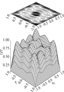
The synthesized DP f 2 (Figure 13) and optimal
amplitude current distributions I (Figures 14-16) at
1 2 are presented. The optimal current distri-
butions correspond to various types of bifurcated solu- tions, namely function
8.0
c c
1 2
arg f s s, which has different parity properties relative to arguments s1 and s2.
In particular, the phase DP argf s s
1, 2
even respect to s1 and s2 corresponds to amplitude distribution I of current presented in Figure 14. As a result this distri-bution is symmetric relatively two coordinate axes. Even
relative to s1 and odd respect to s2 phase DP
1 2
argf s s,
Oycorrespond to non-symmetrical relative to axis amplitude distribution of current in aperture, presented in Figure 15.
In Figure 16, the amplitude distribution I of cur- rent, which correspond to odd relative to s1 and s2 phase DP argf s s
1, 2
, is shown. The synthesized power DP f 2 presented in Figure 13 is created by thiscurrent distribution. This current distribution essentially differs on those presented in Figures 14 and 15.
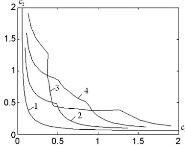
The cross sections of the synthesized power DPs in the
plane 1 demonstrate effectiveness of the synthesis
for the obtained optimal current distributions (see Figure
17). Curve 1 corresponds to prescribed power DP N0,
curves 2, 3, and 4 correspond to amplitude distributions of current presented in Figure 16, Figures 14 and 15,
respectively. One can see that the current distribution
presented in Figure 16 is more effective, because the
synthesized power DP created by it approximate the prescribed DP in the best way; this properties the most evidently is observed in the neighborhood of central zero point.
0 s
Figure 13. The synthesized power DP f 2 of the plane aperture for prescribed DP (29).
Figure 14. The symmetric optimal current distribution.
Figure 16. The optimal current distribution non-symmetric relative to both axes.
0 0.2 0.4 0.6 0.8 1 1.2
-2 -1.5 -1 -0.5 0 0.5 1 1.5 2 1
3 | f(0, s2)|2
s2 2
[image:9.595.353.494.88.269.2]4
Figure 17. The cross sections of the synthesized DP in the plane s10.
5.3. Plane Rectangular Equidistant Array
The results of synthesis for the prescribed power DP
0 are shown for the solutions with properties 1)
(Figure 18) and properties 2) (Figure 19); the
equidis-tant plane array consisting of radiators is
examined. In spite of the fact that phase DP 1
N
11 11
N
arg f for
the latter solution is odd respect to the coordinate s2 the
synthesized power DP f 2 is even relative to s1 and
2
s , but the value of mean-square deviation of the
pre-scribed and synthesized power DPs for the latter solution is equal to 0.0562 against 0.0897 for the solution of type 1).
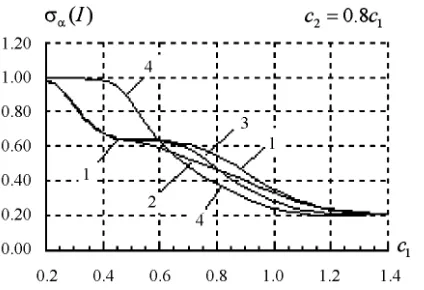
In order to demonstrate the effectiveness of synthesis for the different type of solutions, the value of functional are shown for the solutions of type 1) - 4) at
2 1, 1 , (see Figure 20). The
numbers of lines corresponds to types of solutions. One can see that the solution of type 4) provides the worst approximation of the prescribed power DP. The even relative to
0.8
c c c 1.0
1
0.5
s and s2 solution is more optimal for such
Figure 18. The synthesized power DP f 2 corresponding to solution of type 1).
Figure 19. The synthesized power DP f 2 corresponding to solution of type 2).
Figure 20. The value of functional for different types of solution to Equation (11), .
0 1
N
prescribed DP in the considered range of 1 and . 2 The effectiveness of synthesis also depends on the
[image:9.595.357.488.313.502.2] [image:9.595.84.261.324.450.2] [image:9.595.329.512.547.673.2]form of the prescribed power DP considerably. The syn- thesis results for the prescribed power DP
0 1, 2 sin π1 sin π 2
N s s s s (30)
are presented in Figures 21 and 22. The synthesized
power DP for the same values N, c1, c2, and as in the previous example is shown in Figure 21. The initial
approximation odd relative to s1 and s2 was given for iterative process (28). Such type of approximation pro- vides the smallest value of
0.64
among the solutions with properties 1) - 4). In Figure 22, the values of functional are shown for the solutions of type 1) - 4). One can
see that solution of type 4) provides the worst value of
at 1 , at 1 this solution is the best
among the considered ones. The solution with the phase DP arg f even respective to 1
c 0.6 c
s and s2 is the better for
, but is the worst for the values .
1
[image:10.595.96.251.300.516.2]c 0.49 c10.63
Figure 21. The synthesized power DP f2 corresponding to solution of type 4).
Figure 22. The value of functional for different types
of solution to Equation (11) for prescribed power DP (30).
5.4. Plane Hexagonal Array
The synthesis results are presented for prescribed power DP N s s0( , ) 11 2 and DP (29). The array consisting of
127 radiators is considered, parameter . The syn-
thesis problem is reduced to solving Equation (11) by the method of successive approximations (28). The main lobe of synthesized power DP
0.5
2
f for the prescribed N0
is narrower than the main lobe of prescribed DP. The
maximal deviation of the both DPs does not exceed −10
dB in the main lobe; the level of the first side lobe does
not exceed −45 dB. The mean-square deviations (values
of the first summand in (9)) are equal to 0.3774 and 0.2218 for the first and second prescribed DPs, respec- tively. The level of the first side lobe for the prescribed
DP (29) does not exceed −35 dB. The plots of synthe-
sized power DPs f 2 are shown in Figures 23 and 24.
In Figures 25 and 26, the cross-sections of both the pre-
scribed and synthesized DPs in the planes s10 and
2
[image:10.595.310.536.324.496.2]s 0 are shown.
Figure 23. The synthesized power DP f2 for N01 at
.
1= 2.0, = 2.2362
[image:10.595.309.537.531.708.2]c c
[image:10.595.71.283.562.707.2]Figure 25. Cross-section of the synthesized DP f 2 in the planes s10 and s20 for N01.
Figure 26. Cross-section of the synthesized DP f 2 in the planes s10 and s20 for the prescribed DP (29).
The solid line per
0 N
0
presents the cross-section of the prescribed power DPs N0, the dashed lines 1 and 2 cor-
responds to the synthesized DPs in the cross-sections
1 and 2 , respectively. The level of the first
side lobe for the synthesized power DP 0
s s
2
f does not
exceed −50 dB in the plane and −36 dB in the
plane 2 for case if DP 0 is synthesized. For
the case of DP (29), these values are −52 dB and −35 dB, respectively. The level of side lobes grows considerably
if either the values and , or number of radiators in
array decrease.
1 0
s 1
N
2
0
s
1
c c
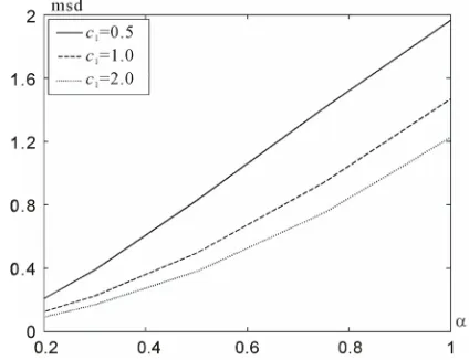
The quality of approximation to the prescribed power
DP depends also on the parameter in functional (7).
The dependence of mean-square deviation (msd) of the prescribed and synthesized power DPs on the parameter
at the various 1 on the beam 2 1 is
shown in Figures 27 and 28. Such ratio of 1 and 2
provide the regularity of the array geometry, and, as the
c c 1.118c
c c
Figure 27. The msd value versus parameter for the pre- scribed DP N01.
Figure 28. The msd value versus parameter for the pre- scribed DP (29).
numerical calculations showed, gives possibility to ob-
tain close DPs in the planes 1 and 2 .
The maximal value of msd for the prescribed DP
0
0
s s 0
1
N is attained at 1.0 for 1 , and it is
equal to 1.96443. The value of msd diminishes as 0.5
c
decreases almost linearly. The maximal value of msd for DP (29) is equal to 1.43685. As is easy to see that in the general the value of msd diminishes as decreases, but the value of the second term in functional (7) (con- tainning terms with the current’s norm) grows considera- bly that yields in total increase of .
6. Conclusions
[image:11.595.312.530.293.463.2] [image:11.595.62.279.300.476.2][12] W. F. Crosswell, T. Durham, M. Jones, D. Shaubert, P. Friederich and J. Maloney, “Wideband Arrays,” In: Mo- dern Antenna Handbook, Wiley, Interscience, New York, 2008, pp. 581-607.
tained solutions. The numerical results of synthesis, de- monstrated for several prescribed power DPs, testify about existence of the various types of solutions which differ by the parity of phase DP. It is shown that the same value of msd in functional is attained at the various
values of 1 and 2 depending on the type of initial
approximation. This gives the possibility to choose the
solution corresponding to smaller values of 1 and ,
and as result, to reduce the antenna size on 10% - 20%.
c c
c c2
[13] S. P. Skobelev, “Phased Array Antennas with Optimized Element Pattern,” Artech House, London, 2011.
[14] R. G. Ayestarana, J. Laviadab and F. Las-Herasc, “Real- istic Antenna Array Synthesis in Complex Environments Using a MOM-SVR Approach,” Journal of Electromag- netic Waves and Applications, Vol. 23, No. 1, 2009, pp. 97-108. doi:10.1002/0470028548
The use of the generalized parameters 1 and 2 de-
scribing the electrical size of antenna and region of the prescribed power DP N0 allows examining the directivity
properties of the investigated radiation systems in the wide range of frequencies and geometrical parameters of antennas.
c c
[15] P. A. Savenko and L. M. Pasnak, “Numerical-Analytical Method of Synthesis for Linear Array of Vibrators with due to Mutual Coupling according to Prescribed Ampli- tude Radiation Pattern,” Izvestiya Vuzov. Radioelectron- ics, Vol. 40, No. 12, 1997, pp. 11-25.
[16] D. A. Morgan, “Handbook for EMC Testing and Measu- rement,” IET Press, London, 2007.
REFERENCES
[17] V. I. Dmitriev and N. I. Berezina, “Numerical Methods ofSolution of Synthesis Problems for Radiating Systems,” Publ. MSU, Moscow, 1986.
[1] C. A. Balanis, “Antenna Theory: Analysis and Design,” 3rd Edition, Wiley-Interscience, New York, 2005.
[18] P. A. Savenko and M. D. Tkach, “Structure of Solutions of the Synthesis Problem for Linear Microstrip Array Us- ing the Power Criterion,” Izvestiya Vuzov. Radioelectron- ics, Vol. 46, No. 1, 2004, pp. 38-49.
[2] L. D. Bakhrakh and S. D. Kremenetskyi, “Synthesis of Radiating Systems (Theory and Methods of Design),” Sov. Radio, Moscow, 1974.
[3] B. M. Minkovich and V. P. Yakovlev, “Theory of Anten-
na Synthesis,” Sov. Radio, Moscow, 1969. [19] M. A. Krasnoselskyi, G. M. Vainikko and P. P. Zabreyko, “Approximate Solution of Operator Equations,” Nauka, Moscow, 1969.
[4] Ya. S. Shifrin, “Problems of Statistical Theory of Anten- nas,” Sov. Radio, Moscow, 1970.
[20] P. A. Savenko, “Synthesis of Linear Arrays according to Prescribed Amplitude Radiation Pattern,” Izvestiya Vuzov. Radioelectronics, Vol. 22, No. 12, 1979, pp. 1498-1504. [5] W. L Stutzman and G. A. Thiele, “Antenna Theory and
Design,” 3rd Edition, Wiley, London, 2013.
[6] E. G. Zelkin and V. G. Sokolov, “Methods of Antenna Synthesis. Phased Arrays and Antennas with Continuous Aperture,” Sov. Radio, Moscow, 1980.
[21] V. F. Kravchenko, L. P. Protsakh, P. A. Savenko and M. D. Tkach, “Mathematical Features of Synthesis of Plane Equidistant Arrays according to Prescribed Amplitude Radiation Pattern,” Antennas, Vol. 3, No. 154, 2010, pp. 34-48.
[7] J. N. Sahalos, “Orthogonal Methods for Array Synthesis,” Wiley, New York, 2006, doi:10.1002/0470028548 [8] E. G. Zelkin, V. F. Kravchenko and V. I. Gusevskyi,
“Constructive Methods of Approximation in Antenna Theory,” Science Press, Moscow, 2005.
[22] P. A. Savenko and L. P. Protsakh, “Method of Implicit Function Applying to Solution of Two-Dimensional Non- linear Spectral Problem,” Izvestiya Vuzov. Radioelectron- ics, Vol. 11, No. 546, 2007, pp. 41-44.
[9] V. F. Kravchenko, “Atomic and R-Functions in Radio- physical Applications (Review),” Proceedings of 7th In- ternational Conference on Antenna Theory and Techni- ques (ICATT-2009), Lviv, 6-9 October 2009, pp. 3-12.
[23] M. M. Veinberg and V. A. Trenogin, “Theory of Branch- ing of Solutions to Nonlinear Equations,” Nauka, Mos- cow, 1969.
[10] M. I. Andriychuk, N. N. Voitovich, P. A. Savenko and V. P. Tkachuk, “Antenna Synthesis according to Amplitude Radiation Pattern: Numerical Methods and Algorithms,” Nauk. Dumka, Kiev, 1993.
[24] P. O. Savenko and M. D. Tkach, “Antenna Synthesis with Flat Radiating Aperture according to the Prescribed Di- rectivity Pattern by Power,” Proceedings of 17th Interna- tional Seminar/Workshop DIPED-2012, Tbilisi, 24-27 September 2012, pp. 75-80.