Design and Implementation of a Sliding Mode Attitude
Controller of a Satellite in Software in the Loop Test Bed
Farhad Fani Saberi
Space Science and Technology Institute, AmirkabirUniversity of Technology Tehran, Iran
Alireza Fazlyab
Department of MechanicalEngineering, Amirkabir University of Technology
Tehran, Iran
Abbas Ajorkar
Department of MechanicalEngineering, Amirkabir University of Technology
Tehran, Iran
ABSTRACT
In this paper, a robust attitude control algorithm is developed based on sliding mode control for a satellite using four reaction wheels in a tetrahedron configuration. In this method, asymptotic stability of the proposed algorithm has been proven on lyapunov theory. Then, in order to evaluate the performance of the proposed algorithm, a low-cost real-time software in the loop test bed is provided. The presented test bed is capable of real-time assessing the attitude sliding mode control algorithm. In this test bed, real-time modeling of satellite dynamic, environmental disturbances and reaction wheels are achieved in a simulator computer and the proposed control algorithm performance is investigated by implementing it in an electronic control board of the software in the loop test bed.
Keywords
Attitude Control; Reaction wheel; Satellite; Sliding Mode; Software in the loop
1.
INTRODUCTION
A spacecraft requires several subsystems to achieve its mission successfully. Attitude determination and control system (ADCS) is one of the most crucial subsystems of a spacecraft. The major tasks of attitude control system are to provide the capability of high maneuverability, high pointing stability and attitude accuracy for the satellite. This subsystem has different parts including, sensors, actuators, control algorithm and electronic control board. The control algorithm is an important part of ADCS that provides commands for actuators.
Difficult problems in the design of control algorithm for such a complex dynamic system are due to the inherent nonlinearities of the model because of large angle maneuvers, uncertainties and unknown environmental disturbances. Among the research that has been done recently, there are a number of techniques that can deal with the control problems of such a complex dynamic system from classical PID control to adaptive control e.g. optimal control [1], sliding mode control [2], adaptive control [3, 4], robust control such as variable structure control (VSC) which are designed based on Euler angle errors or quaternion error vector.
The control algorithms in [5, 6] are based on variable structure control (VSC). Robustness is one of the most distinguishing properties of VSC systems. The VSC of multi axial spacecraft for large-angle rotational maneuvering has been studied in [7]. In [8], a sliding mode control method has been presented for command tracking of spacecraft maneuvers based on Euler parameters. In [7], a sliding attitude control
algorithm based on variable structure control has been designed using quaternion parameters. In [9], a sliding mode control technique has been developed for spacecraft pointing and regulation using Rodriguez (Gibbs vector) representation. Moreover in [10, 11], sliding mode controller has been developed based upon the modified Rodriquez parameters which provides large angle maneuvers for a satellite. But in these methods, the effects of actuator dynamics and external disturbances have not been considered. Moreover, due to high cost and high risk of complex systems such as satellites, functional tests of most subsystems are highly desirable before launch. One solution to achieve functional tests of ADCS is to use software in the loop (SIL) approach, where is a low cost and applicative test bed [12].
In this paper, a sliding mode attitude controller will be designed based on variable structure control (VSC) using four reaction wheels in a tetrahedron configuration. Then asymptotic stability of the proposed algorithm has been proven on lyapunov theory. Then software in the loop test bed will be designed and manufactured to evaluate the performance of the proposed attitude control algorithm in a real-time condition. The presented software in the loop test bed is capable of real-time assessing the attitude sliding mode control algorithm. In this test bed, real-time modeling of satellite dynamic, environmental disturbances and reaction wheels and gyros are achieved in a simulator computer and the proposed control algorithm performance is investigated by implementing it in an electronic control board of the software in the loop test bed.
2.
DYNAMICS AND KINEMATICS OF
SATELLITE
The general equation to describe the attitude motion of a rigid satellite in space (Euler equations) in the presence of momentum exchange devices (e.g., reaction wheels) is described as follows [13]:
J
J uJ1 1
(1)
0 0
0
1 2
1 3
2 3
J J
J J
J J J
(2)
moment of inertia of the reaction wheels and C is the orientation matrix of the wheels. To provide high roll and pitch control torque as well as high speed slew capability, we consider a rigid spacecraft model with a set of four reaction wheels which are arranged in a pyramid configuration about the spacecraft yaw axis as shown in Fig 1.
RW1
RW4
RW2
Z, Yaw
Y. Pitc
hX, Roll
90-β
α
[image:2.595.61.255.146.297.2]RW4
RW3
Fig 1: Four reaction wheels configuration
The orientation matrix of the above four-wheel pyramid configuration represented by a 3 × 4 matrix (C) which is considered as follow:
cos cos
cos cos
sin cos sin sin sin cos sin sin
sin sin sin cos sin sin sin cos
C
(3)
Where columns of matrix are the wheel axial vectors. and are considered as 45 and 54.74. In order to represent the kinematics equations of the satellite we will used modified Rodrigues parameters (), where is a 31
vector. Thus the kinematic equations of motion of the satellite are given as follow [14]:
F (4)
(1 ) )2 1 (
2 1 )
( 33 33
I I
F T T (5)
Where I33 is a33 identity matrix and
is a 33 “cross product” matrix defined by equation (6).
0 0 0 ) (
1 2
1 3
2 3
(6)
3.
REACTION WHEEL MODEL
In general, a reaction wheel – the type of the actuator that has been used in the ADCS system in this paper- consist of a rotating flywheel, typically suspended on ball bearings and driven by an internal brushless DC motor.
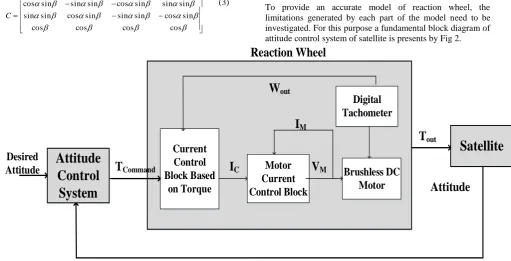
To provide an accurate model of reaction wheel, the limitations generated by each part of the model need to be investigated. For this purpose a fundamental block diagram of attitude control system of satellite is presents by Fig 2.
Attitude
Control
System
Satellite
Current
Control
Block Based
on Torque
Motor
Current
Control Block
Brushless DC
Motor
Digital
Tachometer
T
CommandI
CV
MI
MW
outT
outAttitude
Desired
Attitude
[image:2.595.50.562.362.623.2]The sliding mode controller which produces a negative definite derivative of the Lyapunov function is given by:
() (,) m G Ksats
f J u
J
J
J TEXT f 1 1(9)
Where Kis a 33 positive definite, diagonal matrix, and is a small positive quantity. The saturation function that is used to minimize chattering in the control torques,G() and
m
are defined by
i i i i i i s for s for s s for s sat 1 1 , (10) ) )] 1 ( 2 1 [ ) ( ( 2 1 )( I I
G T T (11)
Td T T T T d d T d T d T T T T I I I m } 2 2 ) 1 {( ) 1 ( 16 ) ( ) 1 ( 8 } ) 1 ( 2 ) 1 ( 4 3 3 3 3 3 2 1 3 3 1 (12)
The asymptotic stability of the designed attitude controller has been proved by defining a positive definite Lyapunov function
t s sV T
2 1
. Then V
t is obtained as follow:
t s s s
m
s
f
J u m
V T T T 1
J u mF
f s t
V T 1
F m s sat K F m f J J f sT , 1
t s Ksat
s W
s V T , (13)
sW is a positive definite function, so V
t is negative definite and asymptotic stability has been proved.5.
SOFTWARE IN THE LOOP TEST
BED
The In this section, a software in the loop test bed will be proposed to evaluate the performance of the designed attitude control algorithm in a real-time condition. Configuration of the software in the loop contains three main parts including: simulator computer, on-board electronics and an interface circuit for exchanging data between simulator computer and on-board electronics.
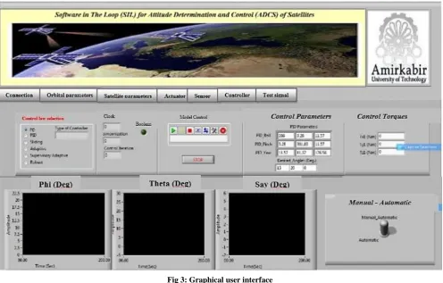
Simulator computer provides a simulation base in software in the loop test bed. The tasks of simulator computer can be expressed as: 1) modeling of orbital motion of satellite, rotational motion of satellite, environmental disturbances and actuators and sensors dynamics 2) providing a graphical convenient user interface for monitoring system performance. Accurate modeling of satellite dynamics and space conditions has major role in design of test bed. For satisfying this requirement, a software simulator is implemented in SIMULINK environment of MATLAB. In this simulator, accurate simulation of orbital motion of satellite, rotational motion of satellite, disturbances torque applied to the satellite, accurate model of reaction wheels and gyro are implemented. In this simulator, modeling is done based on high fidelity mathematical models, e.g. modeling of orbital dynamic is done based on KEPLER equation for Elliptical orbits [13]. Modeling of satellite attitude is implemented based on Euler’s equations in [13]. Modeling of reaction wheels are implemented based on equation in [15]. Also to modeling disturbances, four common disturbances in low Earth orbit are considered including, gravity gradient, aerodynamic, geomagnetic and solar radiation torques [16].
In the designed test bed, RS232 serial communication protocol has been used to transfer data between simulator computer and on-board electronic .Designed software in the loop test bed operate as follow: at first, technical specification of the satellite, including the moment of inertia, mass and geometric properties, initial conditions of attitude and angular velocity of satellite after launch, desired attitude and maneuvers, orbital characteristics and specifications of reaction wheels and gyros, should be defined in graphical user interface software.
[image:4.595.57.554.79.396.2]In this structure, the attitude determination information will provided by DLL file corresponding to dynamic model of the satellite. Then attitude information transferred to the on-board electronics through the serial port. On-board electronics uses these data to compute control torque and reaction wheels torques using attitude control algorithm based on receiving data including attitude and angular velocity of satellite. Calculated control torques transferred through the serial port to simulator computer and in DLL model, new attitude of the satellite will be computed. This loop will continue in real-time condition. Fig 4 shows hardware in the loop test bed and
Fig 4: Software in the loop test bed equipment
6.
IMPLEMENTING ATTITUDE
CONTROL ALGORITHM IN THE
SOFTWARE IN THE LOOP TEST BED
In this section, the simulation results of our proposed sliding mode controller in MATLAB/Simulink environment compared with control based on Euler angle errors, control
to body reference frame is assumed Idiag
1000,500,700
and controller parameters and characteristics of reaction wheels according with specification states in reference [17] are listed in Table 1. Desired Euler angles are assumed
, 25 , 20
0
d d
d
.
[image:5.595.315.524.76.466.2]Fig 5 to Fig 7 show the simulation results of our proposed sliding mode controller compared with common attitude controllers. Fig 8 to Fig 12 show the results of our proposed sliding mode controller which is implemented in software in the loop test bed in presence of actuator dynamic and environmental disturbances Also 25 percent uncertainties on the moments of inertia have been considered to demonstrate the robustness of the controller.
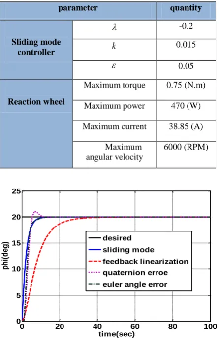
Table 1. Simulation parameters parameter quantity
Sliding mode controller
-0.2
k 0.015
0.05
Reaction wheel
Maximum torque 0.75 (N.m)
Maximum power 470 (W)
Maximum current 38.85 (A)
Maximum angular velocity
6000 (RPM)
[image:5.595.317.524.77.235.2]Fig 5 : comparison the performance of sliding mode controller with other controllers for roll axis
[image:5.595.57.280.241.586.2]Fig 6 :comparison the performance of sliding mode controller with other controllers for pitch axis
Fig 7 : comparison the performance of sliding mode controller with other controllers for yaw axis
Fig 8 : Implementation of sliding mode controller for all roll in the software in the loop
0 20 40 60 80 100
0 5 10 15 20 25
time(sec)
p
h
i(
d
e
g
) desired
sliding mode
feedback linearization
quaternion erroe
euler angle error
0 20 40 60 80 100
0 5 10 15 20 25 30
time(sec)
t
h
e
ta
(d
e
g
)
desired sliding mode feedback linearization quaternion error euler angle error
0 20 40 60 80 100
-4 -3 -2 -1 0 1 2 3
time(sec)
s
a
y
(d
e
g
)
[image:5.595.315.544.498.700.2]Fig 9 : Implementation of sliding mode controller for all pitch in the software in the loop
Fig 10 : Implementation of sliding mode controller for all yaw in the software in the loop
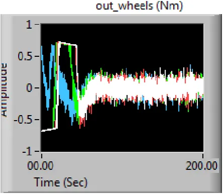
Fig 12: Angular velocity of reaction wheels in the software in the loop test bed
[image:6.595.53.282.292.481.2]The error control of roll, pitch and yaw axis are 0.12, 0.58 and 0.04, respectively, which indicates that designed sliding mode controller despite 25 percent of uncertainty on moment of inertia, unknown disturbances, actuator dynamics works properly and designed software in the loop test bed are capable of executing control law accurately. Table 2 presents the simulation and implementation results. Comparing simulation and implementation result show some deviation among these results. The major source of deviation is originated from delay time corresponding to transmission data between on-board electronic and simulator computer. Note that since in real operation in orbit, there is no need to transfer data between the on-board electronic and the computer, so the mentioned error is not problematic.
Table 2. Result of simulation and implementation
Axis
Steady state Error
Simulation (deg)
Implementation (deg)
Difference between simulation and implementation (%)
Roll 0.12 0.05 0.35
Pitch 0.58 0.49 0.36
Yaw 0.04 0.22 3.6
[image:6.595.55.277.520.713.2]test. However there are some deviations between simulation and practical results but these deviations are not critical and the proposed algorithm achieve attitude control mission properly
8.
REFERENCES
[1] Chelaru, T. V., Cristian, B., and Chelaru, A 2011. Mathematical model for small satellites, using rotation angles and optimal control synthesis. In Recent Advances in Space Technologies (RAST), Istanbul, Turkiye.
[2] Qinglei, H. 2008. Sliding mode maneuvering control and active vibration damping three axis stabilized flexible spacecraft with actuator dynamics. Nonlinear Dynamics, vol. 15, pp. 227-248.
[3] Moradi, M. 2013. Self-tuning PID controller to three-axis stabilization of a satellite with unknown parameters. International Journal of Non-Linear Mechanics, vol. 49, pp. 50-56.
[4]Shahravi, M., Kabganian, M., and Alasty, A. 2006. Adaptive robust attitude control of a flexible spacecraft. International Journal of Robust and Nonlinear Control, vol. 16, no. 6, pp. 287-302.
[5] Song, Z., Li, H., and Sun, K. 2014. Finite-time control for nonlinear spacecraft attitude based on terminal sliding mode technique. ISA Transactions, vol. 53, no. 1, pp. 117-124.
[6] Hu, G. 2009. Variable Structure Maneuvering Control with Time-Varying Sliding Syrface and Active Vibration Damping of Flexible Spacecraft with Input Saturation. Acta Astronautica, vol. 64, pp. 1085-1108.
[7] Vadali, S. R. 1986. Variable Structure Control of Spacecraft Large Angle Maneuvers. Journal of Guidance, Control and Dynamics, vol. 9, pp. 235-239.
[8] Wu, S. N., Sun, X. Y., Sun, Z. W., and Chen, C. C. 2011. Robust sliding mode control for spacecraft global fast-tracking manoeuvere. Journal of Aerospace Engineering, vol. 225, pp. 749-760.
[9] H. S. Ramirez and T. A. W. Dwyer, "Variable Structure Control of Spacecraft Reorientation Maneuvers," in Proceedings of AIAA Guidance, Navigation, and Control Conference, Williamsburge, 1986.
[10] Marandi, S. R., and Modi, V. J. 1987. A Preferred Coordinate System and Associated Orientation Representation in Attitude Dynamics. Acta Astronautica, vol. 15, pp. 833-843.
[11] Shuster, M. D. 1993. A Survey of Attitude Representations. The Journal of the Astronautical Sciences, vol. 41, pp. 439-517.
[12] Bolandi, H., Haghparast, M., Saberi, F. F., Vaghei, B. G., and Smailzadh, S. M. 2012. On-Board Electronic Of Satellite Attitude Determination and Control Subsystem: Design and Test in Hardware in the Loop Test Bed. The Journal of Institute of Measurement and Control, vol. 45, no. 5, pp. 151-157.
[13] Sidi, M. J. 1997. Spacecraft Dynamics and control: a practical engineering approach. Cambridge University Press.
[14] Crassidis, J., and Markley, F. 1996. Sliding Mode Control Using Modified Rodrigues Parameters. AIAA Journal of Guidance, Control and Dynamics, vol. 19, no. 6, pp. 1381-1383.
[15] Bolandi, H., Saberi, F. F., and Mehrjardi, A. E. 2011. Design of Attitude Control System of a Satellite with Large Angle Maneuvers Considering of Reaction Wheels Model and Restrictions. Journal of Space Engineering, vol. 1, no. 1.
[16] Wertz, J. 1987. Spacecraft Attitude Determination and Control. London: Kluwer Academic.