Autonomous Driving using a Vision based Approach
Sailesh Sidhwani
Student
Dept.Of Computer Engineering Sinhgad Inst.Of Tech. & Sci.
Pune, India
Monika Malkotiya
Student
Dept.Of Computer Engineering Sinhgad Inst.Of Tech. & Sci.
Pune, India
Nakul Korde
Student
Dept. Of Computer Engineering Sinhgad Inst. Of Tech. & Sci.
Pune, India
Swapnil Unde
Student
Dept, Of Computer Engineering Sinhgad Inst. Of Tech. & Sci.
Pune, India
M. B. Salunke
Asst. Professor
Dept. Of Computer Engineering Sinhgad Inst. Of Tech. & Sci.
Pune, India
ABSTRACT
Driving a vehicle is essentially a subconscious task performed by any human merely with the use of his vision and intelligence. The research in this meadow of designing systems to automate vehicle driving is primarily oriented towards using multiple cameras and 3-D sensors. But this approach is inconsistent with the natural behaviour of humans. This paper presents some of the facets of autonomous driving using the senses analogous to what humans possess - Vision and Intelligence; both artificial in this case. Methodologies to implement the same are designed wherein a single camera when complemented by a convex mirror will capture an omnidirectional view of the surroundings, eliminating the necessity of laser sensors. Further, techniques are illustrated to plan the path of the vehicle by applying complex transform equations on the circular images appearing on the mirror captured by the camera. A steering mechanism is designed where an assembly consisting of a DC motor and a potentiometer is used to plan and control the exact degree of rotation of the steering wheel. This paper substantially aims at providing economical implementation solutions towards developing simplified autonomous vehicle driving control systems.
General Terms
Image Processing, Artificial Intelligence, Embedded systems, Arduino
Keywords
Autonomous Vehicle, Omni-directional Camera, Vision Based Approach.
1.
INTRODUCTION
Autonomous vehicle has been the dream of researchers for almost the last four decades. After the research and development through the years in this field, this concept is on the verge of leaving the prototype stage and come up as a reliable commercial product.
Automated vehicles are something that will dramatically change the transportation system infrastructure in more than one aspect. They will reduce the dependency on human driving which will result in a regulated and civilized driving scenario eventually leading to lesser carnage on the roads. Automation of public transport vehicles will result in an optimal coordination between the public as well as private transport and henceforth a fuel efficient transport system and a controlled pollution rate. Hence, this has transformed into a
need over the years of development. The challenges faced in the development of autonomous vehicles are to provide reliability, security and cost efficiency. After working in the same direction, efficient, impeccable and cost effective solutions have been derived.
The first step in achieving automation of ground vehicles is to sense the obstacles on the road as well as keep the vehicle itself on the road. To sense the obstacles on the road, images have to be captured and processed upon. Most of the implementations are done using advanced three-dimensional image sensors, but, apparently humans do not possess any such advanced image sensors. Our approach is to install the vehicle with an assembly of a 2D camera along with a convex mirror. This provides us with an omnidirectional view of the surroundings with just a single camera. These images are fed to the built in computer which processes these images and provides the further signals for hardware control.
Fig. 1 System working Overview
Designing efficient hardware control was a challenge. To overcome this challenge, a hardware control system is designed. Arduino is used as the central controller for the hardware control unit. The Arduino communicates with the in built computer via a serial communication port and forwards these signals to the other hardware control modules. In this paper, implementation aspects of autonomous vehicles have been further illustrated.
2.
IMPLEMENTATION ASPECTS
While creating only a prototype model of autonomous vehicle various issues have to be handled which any manned vehicle would have to face in real time. It has been tried to keep the implementation as closely related to vision based approach. For this purpose the entire project is divided into various layers The output from Sensing Assembly (Omni-Directional Camera) is provided to Central Processing Unit which implements Image Processing and in turn handles Hardware Control.
Fig. 2 System Architecture
2.1
Steering Mechanism
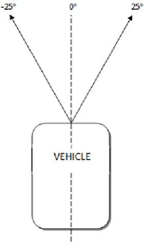
[image:2.595.350.493.193.438.2]The steering mechanism of vehicle is responsible to control; the angle with which the prototype will drive upon road with respect to center of the lane in which prototype is. The steering mechanism is constructed using a variable resistance whose shaft rotate in accord with the shaft of the vehicle prototype. The shaft of the variable resistance and vehicle are connected through a simple gear assembly which transfers rotation of shaft of vehicle to that of variable resistance without any step up or step down of rotation.
Fig. 3 Steering Mechanism Mapping
A 9V input is provided to variable resistance through 7809(voltage regulator) on the main circuit and analog values from output of variable resistance which range from 0 to 1023 are connected to analog port of arduino. To maintain constant current at input of variable resistance a high value capacitor is also used. The analog values are mapped to degree angles which range from -25o to 25o with respect to central axis of vehicle.
The steering of vehicle is controlled through a code burned in micro controller present on arduino chip. The software part mainly deals only with angles mapped to analog variable resistance values rather than the values themselves. This makes control of steering very simple and robust as it is done with the physical angle of steering mechanism. The DC steering motor gets its input in form of angle to which it should rotate irrespective of current angle from arduino.
2.2
Omni-Directional Camera
[image:2.595.58.279.511.700.2]Fig. 4 Omni-Directional Camera Assembly
The use of a high definition video camera gives a 2D image but is way cheaper than the advanced 3D sensors. This gives our system an economical advantage. Autonomous vehicles are still a pretty futuristic concept, hence making them economically feasible remains to be a challenge. Most of the efficient systems that are in development today typically depend on 3D sensors for their image sensory purpose. But, as it is known that humans do not possess any such advanced image sensors, then it is expected that a machine should be able to do the same with the use of 2D image sensors and hence, this stood as our motivation towards designing this assembly.
The use of 3D image sensors demands the processing of such high complexity images. These images require the processing unit to be of a very high computational power, resulting in a high computational overhead. The use of 2D image sensors provide relatively less complex images and information can be extracted from them with relatively simpler complex algorithms. Hence, the time complexity of the entire processing algorithm is scaled down reducing the computational overhead to a great extent. Hence, this assembly provides a simpler solution to a rather complex problem.
Fig. 5 Field of view of Omni-Directional Camera
2.2.1
Curve Fitting
The image that is captured in this assembly is notably circular in shape. Hence, all the objects that appear in the image are obviously distorted. So how can the information be extracted from it? To this issue a solution that was figured out was „curve fitting‟. Curve fitting is the process wherein a curve is
constructed that plots the real life data points to the points as they appear in the image.
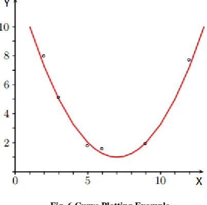
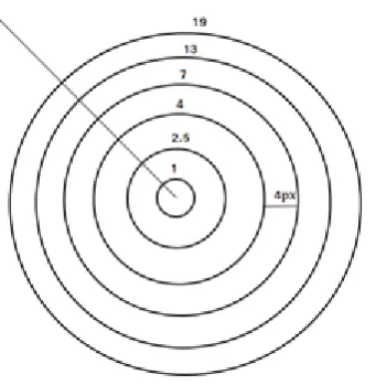
[image:3.595.321.523.323.523.2]Curve fitting or curve approximation is the process of constructing a curve that has the best fit to a series of already known data points, subject to some constraints. It can be implemented using interpolation or smoothing function. Interpolation is where exact fit to data is required. In smoothening, the machine tries to fit the curve to the given coordinates. Here it tries to smoothen the curve in each iteration by applying the smooth function and tries to fit the curve as far as possible. Fitted curve is used for data visualization for those values whose data points are not available. For our example it is needed to find the exact distances of an obstacle from vehicle so as to take run time decisions like apply brake or so on. As shown in fig THIS the contours represent equally spaced concentric circles each at distance of 4 pixels from prior one. Our aim is to find a curve function which when provided with a data point i.e. number of pixels from the center will give output as a number which represents actual distance in real world. This output will ultimately be used by the system to take decisions for the vehicle operation.
Fig. 6 Curve Plotting Example
Consider the following example; the curve should pass through following points:
(2,8), (4,5), (5,2), (6,1.8), (9,2), (12,8). When the method of smoothing is used for curve approximation the following output is obtained.
[image:3.595.99.241.509.675.2]Fig. 7 Sample Image for Omni-directional camera
For our example X coordinate of our graph will be number of pixels in the image an Y coordinate will represent actual real life distances for corresponding pixels. Since convex mirror is used which is in shape of parabola whose equation is quadratic in power. The general conic equation for parabola is A(x2) + B(xy) + C(y2) + D(x) + E(y) + F = 0. Thus it can be assumed that the curve which will be generated will be quadratic in nature.
2.3
Hardware Control Layer
Our system is a real time one, consisting of modularised hardware units. Modularizing the different sections of the hardware control unit further requires an efficient communication system for the communication between the modules for sending data and control signals. A communication system is also required for the communication between central processing unit and hardware control unit. The central processing unit directs the hardware unit which in turn signals the actuators regarding their motion. For the same, a good communication medium is required.
For reliable functioning, designing an efficient hardware control was a challenge. To overcome this challenge, a hardware control system is developed. Arduino Uno is used as the central controlling unit for the hardware control system. As previously mentioned, the system is a real time one, hence, the communication system that was developed was supposed to have a minimum response time. Arduino, which has well-developed serial communication interface served this purpose well. So our communication system consists of Arduino Uno.
Arduino works at 9 Volts input supply and is serially connected to the control system. The purpose of using Arduino is essentially because it has a very efficient serial communication interface. Arduino is open source and has free libraries and a very good development environment. Moreover, use of Arduino makes debugging of the system an easy task.
Our hardware control unit consists of various components with different specifications. Therefore, power supply to each component is regulated at different levels as per the requirement of the respective components through the voltage regulator ICs.
Control system directly communicates with Arduino. Arduino gives signals to the motor drivers and the DC motors work accordingly. Opto-couplers are used in between the Arduino and motor-drivers so as to protect the Arduino from reverse
current via the motors. Opto-coupler is used to remove the physical connection between two sections of the circuit. It basically isolates the two sections from each other. Thus, the reverse current caused due to motor rotation would not affect the Arduino.
The rear motors were draining excess current from the battery. This would have affected the L293D motor driver. To avoid this, a Mosfet motor driver circuit is used for controlling rear motors. The Mosfet motor driver circuit can easily handle the high current drainage by the rear motors.
Control system takes input from our omnidirectional image sensory system. The input is processed by central processing unit using image processing and artificial intelligence algorithms, and in result gives directions to the hardware control unit. The hardware control unit further directs the DC motors with the appropriate rotation and to the steering mechanism with the appropriate degree of rotation.
2.4
Image Processing
In this system OpenCV library is used to manifest computer vision for the motion planning of the car. By manifesting computer vision it means that the OpenCV library is being used to implement the image processing algorithms that are required to extract relevant data from the images. The camera via the mirror captures the surroundings which consist of a large number of objects plus the road. So there is a need to extract the coordinates of the road and the obstacles which fall on the road or may come in between the path of the vehicle. Various transform functions have been used in order to extract the relevant data from the images. These transform functions have been illustrated in the successive sections. The motion planning algorithm takes these coordinates as inputs and provides the path for the vehicle to follow.
The images captured by the camera may be noisy and hence have to be preprocessed before being deployed for actual processing. A simple and frequently used image processing operation –Smoothing is employed to serve the purpose. It reduces noise and camera artifacts from the captured raw images. Various smoothing functions are available in OpenCV. In this project the Gaussian filter is used. These noise free images are further subjected to other consecutive image processing algorithms which are used for actual extraction of data from the images.
The next step that is performed is the detection of the road, as the first task of the vehicles is to stay on the road no matter what may happen. Hence, the extraction of the road from the image and then passing these coordinates to the motion planning algorithm is of primary importance.
First step in the algorithm to detect the road is to filter the image in the form needed. To obtain a good image in order to process it, Gamma Conversion is applied on the image. This is necessary because it helps in making the road as dark as possible and thus, removing all the discrepancies that may occur on the image while color detection. The next step is detection of the color black which defines the road. For this, direct thresholding is applied.
mask is created which is superimposed on the image, hence, giving us the extracted road. Now, this road is flood filled with white color, rest all the image is black after being masked.
This extracted road is now subjected to another image processing algorithm, which will give the angle of curvature of the road. In this algorithm, two horizontal lines are drawn at predefined locations on the extracted road and their mid points are compared. After applying Pythagoras theorem on these points, the relative angle between them can be resolved. So, this will give us a direct result whether the car is going out of the road boundary and hence, the appropriate correction can be taken. The onboard computer processes this data and communicates with the hardware control unit in order to give it appropriate instructions. The hardware control unit further controls the actuators.
3.
RESULTS
The system is now functional and it can traverse the roads, detect any obstacles and move past them. Moreover the differential turn is implemented which the vehicle takes when it has to move past any obstacles or overtake other vehicles driving on the road. Various image processing algorithms have been implemented successfully in order to extract relevant information from the captured images. The system as of now is not completely capable of detecting the traffic signals and signs those are mounted along the roadside. This feature is currently being worked upon and refinement of the image processing algorithms in order to incorporate this change is also going on.
4.
CONCLUSIONS
Developing an optimal autonomous vehicle is a not a task that is accomplished completely and hence it still expects immense amount of inputs by researchers. The use of advanced three dimensional sensors is one of the solutions. But it has a large computational overhead associated with it. Moreover, the hardware costs are high in developing such complex systems. The fact that human beings can drive vehicles based merely on the basis of “VISION”, hence, developing such a robust system that uses vision persuades us to develop systems that are simpler, faster and economically feasible as well. The methodologies presented in this paper pave a way towards developing such systems. A completely offbeat scenario can be created wherein autonomous vehicles will be common and within the reach of the common man.
5.
REFERENCES
[1] Mohammad Abdul Qayum, NafiulAlamSiddiqui Mohammad AbtiqulHaque, Abu Saleh Md. Tayeen, “Control of autonomous cars for intelligent transportation system”, International Conference on Informatics, Electronics & Vision,2012.
[2] HeeChang Moon, JaeCheon Lee, JungHa Kim, and DongMyung Lee, “Development of Unmanned Ground Vehicles available of Urban Drive”, International Conference on Advanced Intelligent Mechatronics, Singapore, July 2009.