Hybrid Cache Coherence Protocol for Multi-Core
Processor Architecture
Muthukumar.S
Associate Professor, Department of C.S.E Sri Venkateswara College of Engineering,
Tamil Nadu, India
Dhinakaran.K
PG Scholar, Department of C.S.E Sri Venkateswara College of Engineering,
Tamil Nadu, India
ABSTRACT
The advances in circuit technology with constraints in power dissipation and clocking have led to integrating more processing cores onto a single chip, making it as the dominant processor architecture. This design of multi-core architectures also referred to as Chip Multiprocessors (CMPs) are gaining popularity because they have the potential to drive the future performance gains without any problems of power dissipation and complexity. Nevertheless, in order to run several independent programs in different processing cores requires them to cooperate for a single computation. Thus the communication architecture is the primary focus of research in achieving the scalability of this architecture. Coherence protocols and interconnection networks have resolved some communication gaps, but memory communication through cache has been the focus of attention in CMP. This problem has been addressed with many hardware and software solutions like Directory-based, Snoopy-Directory-based, Snarfing, etc., but the performance of the system is still not up to the level of expectation. The proposed model is to develop a hybrid cache coherence protocol referred as MESCIF (Modified Exclusive Shared Clean Invalid Forward), which combines the advantages of both directory-based and broadcasting protocols. This can be achieved by introducing a small directory based cache (DB-CACHE) and cache-coherence bus (CC-BUS) into the existing CMP architecture which overcomes the problems of existing methods. The architecture is simulated using a modular discrete event driven computer system simulator platform called gem5 simulation tool.
Keywords
Cache Coherence; Directory Based Cache; Chip Multiprocessor; gem5 simulator.
1.
I
NTRODUCTIONMulti-processor systems use two or more central processing units that communicate with each other through a bus or general interconnection network. From early days the semiconductor industries that manufacture multiprocessors in the market have adhered to Moore’s Law in order to gain high performance by increasing the number of transistors and clock frequencies. Various design constraints such as high power consumption, heat dissipation, etc., restricts the designers from increasing frequency of the clock beyond certain limit. So the performance of those multiprocessors cannot be scaled up to the expectation. This limitation led to the development of embedding multiple processing cores onto a single chip. Such multiprocessors are called as Chip Multi-Processors (CMPs). CMPs increase throughput and efficiency of the system
by utilizing multiple simple cores to perform parallel processing on a larger task with less power and heat dissipation.
In CMP each processor core has its own cache memory that is not shared with any other processor cores. This cache memory available with each core enables fast data access by reducing disk access latency in case of a cache hit. The efficiency of the CMPs depends on type of cache mechanism employed, in particular write back caches are more efficient terms of reducing disk access latencies because in this mechanism the changes in the data cached in the cache memory is updated to the disk only when a replacement of the cache block is required. The major issue with such cache mechanisms is that data inconsistency due to concurrent access of same data block in cache memories of different cores. This problem is called a cache coherency problem. Many software and hardware solutions have been developed to address this problem. These solutions are called cache coherency protocols.
The main purpose of these cache coherency protocols is to ensure that the data read by a processor is consistent. They also provide set of rules to keep the data in the cache of a processor consistent. Cache coherency protocols are widely classified into two categories, namely, a directory-based coherency protocol and broadcast-based coherency protocols [1]. Directory-based cache coherency protocol [2] is a coherence mechanism which contains a small directory that maintains coherence between caches. This directory holds information about all the data blocks cached by processor cores. Each processor must check the validity of a data block before copying it to their cache. Whenever any data block is modified the directory either updates or invalidates all the copies cached by other processors. On other hand a broadcast-based coherency protocol does not use any directory to hold the status of cached data blocks. Instead, in broadcast-based coherency protocol, each processor broadcast data request into the system bus. All the processors continuously monitors request messages in the system bus and responds to it whenever the copy of the requested data is stored in their caches.
Although both the directory-based coherency protocol and Snoopy protocols have its advantages, there are some disadvantages in both of them. To overcome those defects, in the proposed work a hybrid cache coherence mechanism that combines advantages of both the protocols to increase the performance of the CMP by reducing the traffic in the system bus is introduced. In this hybrid mechanism a small directory cache (DB-CACHE) is introduced into the chip in order to hold all the all the references to the data blocks cached by the processors. A separate cache coherence bus (CC-BUS) is introduced for handling data request.
2.
RELATED WORK
multiple cache levels in a multi-core processing system. They are snoopy protocols and directory-based protocols. The following two sub sections discusses about the pros and cons of the two protocols and also a brief outline about the dragon protocol which forms the basis of the proposed hybrid cache coherence protocol MESCIF that combines the merits of both directory-based and broadcasting protocols.
2.1
Snoopy protocol.
Snoopy protocol otherwise called as broadcast based protocol achieves services through broadcasting of both request and response into the system bus, And hence it ensures all the request from a processor were sent to other processor cores in a serial manner. Snoopy protocol is generally implemented in ring structure or inter-connection bus of a multi-processor system [3]. Due to its simple structure, snoopy protocol is considered more advantageous than other protocols. Since system bus is an exclusive resource, when the number of processor cores inter-connected with the system bus is large, the efficiency of the protocol drops dramatically [4]. In snoopy protocol all requests are broadcasted in a undifferentiated manner into the system bus and so all the processors connected with the system bus must read the request and it has to check whether its cache contains the requested data block’s copy. This leads to unnecessary consumption of system resources incase when a processor cache does not contain the requested data block’s copy [5]. Similarly, when multiple processors, contains the requested data block’s copy, multiple processors broadcast the response message into the system bus, which arises a need for arbitration function. This leads to an additional cost of arbitration. Snoopy protocols have a single cache write strategy [6]. (i.e.) either to invalidate or update, and a wide variety of snoopy protocol are based on invalidate write strategy.
2.2
Directory protocol
A directory protocol uses a special memory called directory to store all the information related to a data block’s copy that is cached by any processor in a multi-processor system [7]. Whenever any processor needs a data block copy it checks the directory for its current location information. Then, with the obtained information the requestor processor initiates the point to point communication with the designated processor that contains the requested data block’s copy. This makes the directory protocol to overcome the defect of snoopy protocol which sends request and response messages in an undifferentiated manner. Directory protocol ensures that all data requests are serviced in a serial manner. It also creates a possibility to expand cache coherence protocol to a large scale multi-processor system without any broadcasting mechanism.
2.3
Dragon protocol
The dragon protocol is a write-back policy based protocol [8]. In this protocol the following states are specified to each block in a processor (Invalid state, modified state, exclusive state, shared clean and shared modified).The dragon protocol is intended to minimize the amount of store operation that the main memory has to do. It is divided into two shared states, one is the shared clean and another one is shared modified state. The shared clean state denotes that there are sharers and in this state the processor is not the owner of the cache line. The shared
modified state denotes that the main memory is not updated yet and in this state the processor is the owner of the cache line.
3.
BACKGROUND
UNDERSTANDING
The following sub sections provide a brief overview of cache coherence problem that occurs in multilevel cache in a multi-core architecture.
3.1
Multi-level cache
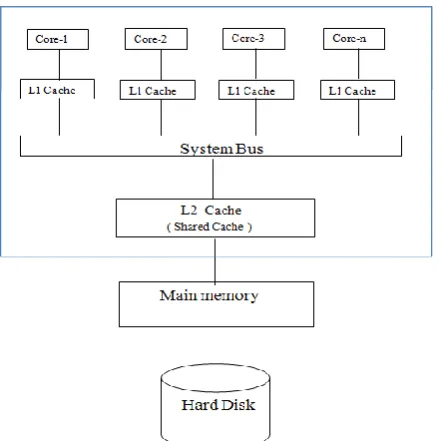
The fundamental issue with the cache memory of any processor is the tradeoff between hit rate and cache latency. When the size of the cache becomes larger, the hit rate increases in the mean time cache latency becomes very longer. In order to reduce the cache latency smaller caches are needed similarly to increase the hit rate a larger cache is needed. To address this problem, the manufactures introduced the multilevel cache concept. Here the cache memory is divided into various levels. The level 1 cache (L1-Cache) which is present inside each cores of a multi-core system was the smallest cache memory that holds the most recently accessed data. Each and every core can have an independent access to its L1-Cache. The next level of caches are larger in size and are shared among multiple processing units (i.e.,) Cores. In a multilevel cache, if a data block is needed, the processor first checks the smallest L1-Cache; if it is a hit then the processor operates at a higher speed; if there is a miss then the processor proceeds to check the next level of cache L2-Cache and so on, before checking the main memory. Fig 1 and Fig 2 shows the presence of L1-Cache and L2-Cache in a multi-core system.
3.2
Multi-Core Processor
In a multi-core processor a single processor chip holds multiple independent CPUs called as cores [9]. Figure 1 depicts the architecture of Multi-Core System architecture. Each core can execute different instructions simultaneously which in turn increases the overall execution speed of programs equivalent to that of parallel computing. A multi-core processor allows multiprocessing using a single physical package. The cores in a core processor may be tightly or loosely coupled. A multi-core system which contains identical multi-cores is called homogeneous multi-core systems. Multi-core processors are mostly used across many real time applications including general-purpose, network, embedded, graphics and digital signal processing (DSP). The performance improvement obtained by using a multi-core processor highly depends on the software algorithms used and their method of implementation.
4.
PROPOSED
SYSTEM
ARCHITECTURE
Figure 1 Multi-core architecture
4.1
Directory Based Cache
A small volume of memory, DB-Cache, serves as a Directory, has been introduced into the existing architecture in order to eliminate the drawback of undifferentiated broadcasting in snoopy protocol. Similarly an additional bus called Cache Coherence bus (CC-BUS) is also introduced to reduce the interconnect bus traffic that arises due to Directory request and response message. The DB-Cache interconnects all the L1 private caches with the help of system bus, holds the valuable information about the data blocks captured in all private L1 caches. Figure 2 shows the proposed architecture with a DB-Cache.
It stores each and every data block cached in private cache of any of the processor along with its address and id of the processor that currently holds the data block. The format of DB-Cache directory items is as follows
Address: Address of the cached Data block’s copy. Condition: Current state information of the data
block’s copy.
Processor-Number: Processor ID in which the data block’s copy resides.
Hence whenever a processor needs any data block, instead of broadcasting the request message into the system bus, it checks the DB-Cache to find the location of the data block using the CC-Bus. After obtaining the location information from DB-Cache, the requesting processor can communicate to any designated processor using point-to-point communication directly.
Figure 2 System architecture with directory based cache.
4.2
Overview of operations performed by the
proposed protocol on a data request
The proposed MESCIF protocol handles any data request using the following sequence of operations: Whenever a data block is needed by the processor,
1. The cache Controller of the requesting processor send a directory request message requesting the required data block’s location, to the DB-Cache through the CC-bus; 2. The DB-Cache controller will respond with a Failure
message if searching directory is not hit, otherwise, returns the processor number that holds the required data block’s copy to the requesting processor;
3. After obtaining the processor number the local cache controller sends a data request message to the remote cache; Remote cache responded to the request by filling the message with data block copy, then sent the request back to the system bus;
4. The local cache controller after receiving the response message from the remote cache, extracts the data block copy.
5.
DESIGN
OF
MESCIF
PROTOCOL
[image:3.595.312.576.74.289.2]5.1
Data block states
M: modified, there exists only one copy of the data block in processor cache but the value of the data block in the cache is different from that of in main memory.
E: exclusive, there exists only one copy of the data block in the processor cache but the value of the data block in the cache is same as that of in main memory.
S: Shared, there exists more than two copies of the data block in the processor’s cache but the value of the data block in the cache is same as that of in main memory.
MC: Master Clean, another copy of the data block existed, and this copy is the leader of two.
SC: Slave Clean, another copy of the data block existed, and this copy is the follower of two.
I: Invalid, there exists a copy of data block which contains an invalid copy. The valid copy may exist either in main memory or remote processor’s cache.
F: Forward, a specialized form of shared state which indicates that it should be the responder for any request for the data block that arises from any remote processor.
Figure 3 shows the state transition diagram for the MESCIF protocol, which contains the above mentioned states and their respective transitions on the following operations.
The operations are:
LW: Local Write, which means that a write operation is performed by same processor on local cache; LR: Local Read, which means that a read operation is
[image:4.595.59.299.422.627.2]performed by same processor on local cache;
Figure 3 State transition diagram
RR: Remote Read, which means that a read operation is performed by the remote processor;
RW: Remote Write, which means that a write operation is performed by the remote processor;
Before requesting the data from the remote processor, the cache controller of the requesting processor must send a directory request message to the DB-Cache using the CC-Bus in
order to get the location information of the required data block. The directory request message format is as follows:
Stage: type of message, takes value either 0 or 1.where 0 indicates it is a request message sent to DB-Cache and a value of 1 indicates it is a conformation message which originates from DB-Cache.
Cate: Type of request, takes value of either 0 or 1 where 0 indicates a read request and 1 indicates a write request.
Source: The processor number from which the directory request message has been sent.
Address: The address of the requested data block. State: Current state of the requested data block’s copy.
Whenever a processor needs a data block’s copy it has to fill the source processor number and set the stage value as zero in the directory request message and this request is placed in the CC-Bus. All processors connected to the CC-Bus and the DB-Cache controller continuously monitors the CC-Bus. On reading this message all other processors discard the message directly after seeing the stage value as 0. Similarly on seeing the value of 0 in the stage field the DB-Cache controller search the directory for the requested data block and place a confirmation message on the CC-Bus which is of the following format:
Here the stage value is set as 1, indicating that it is a confirmation message that is sent from the DB-Cache. The source value is the processor number from the directory request has been generated. The ACK field holds the value of either 0 or 1, representing directory hit or directory miss respectively. Now all the processors monitoring the CC-Bus read the confirmation message checks for the source value whether it is their own processor number, if not the message is discarded directly. Otherwise it checks for the ACK value if it is 0 (i.e.,) directory hit then the source processor sends the data request message (read/write) into the system bus in order to fetch the data block from the remote processor. If the ACK value returned is 1 (i.e.,) Directory miss then source processor sends the data request message to L2 cache.
5.2 Read operation
Source, cate and address in the above format serves the same purpose as mentioned above in the directory request message format.
Stage: Message type, value of 0 represents a data request message originated from DB-Cache and a value of 1 represents it is a response message generated by the remote processor.
Dest: destination represents a processor number where a valid copy of the required data block is present. Data: memory data, it is an area where the remote
processor loads the required data block’s copy.
When a read request message is placed into the system bus all the processors which are monitoring the system bus reads the request message and the following actions are taken:
1) At first the value in the stage field is analyzed, if it is 1 then move to step 3 otherwise checks for the value in the source field whether its processor number is equal to it. If it is not equal then the message is simply discarded otherwise proceed to step 2.
2) Now the value in the dest field is checked, if it is not equal to their own then simply discard the message otherwise read the address field, load the corresponding data block’s copy into the data field and set the stage value as 1. 3) Check for the value in the source field; if it is equal to its
own processor number then read the data available in the data field otherwise simply discard the message.
5.3
Write Operation
During write operation when the data resides in the local private cache and the state of the data block copy was not MC or SC, there is no need of sending data request .The state of the data block is modified both in DB-Cache and local private cache, if it is necessary. When the data to be written is in the processor’s local private cache, and the state of data block copy is either MC or SC, another copy of the data block which resides in the remote processor’s has to updated . When the data block does not reside in the local private cache or the state of the data block is I, then the processing rule are similar to that of read request message. After receiving the data block from the remote processor and completing the write operation need an additional operation of write invalid or write update that has to be performed based on the following rules:
1) If the data blocks copy received is in state E or M then do an update operation by sending a update message through the system bus with cate value has 1 and fill the data with updated value to the remote processor.
2) The state is not E or M do an invalidate operation by sending an invalid return request into the system bus.
6.
IMPLEMENTATIONGem5 [10], a modular discrete event driven computer system simulator is used for simulating the proposed multi-core architecture. We have modified the existing cache coherence
[image:5.595.56.295.72.100.2]protocol MESI of an Alpha processor by adding three states MC, SC and F.The state transitions have been modified in the following files: directory.slicc, dir.sm, directory-dma.sm, directory-L1cache.sm, directory-L2cache.sm and directory-msg.sm. Gem5 can be used to simulate either a complete system with all devices and the entire operating system in a full system mode or user space only programs where the system services are provided directly by the simulation environment in a system call emulation mode. We have used the system call emulation mode in gem5 in order to test the developed MESCIF protocol. Table 1 shows the system parameters of the simulated system.
Table 1. System parameters
Parameter Value
CPU cores 4
L1D Cache 64 KB
L1I Cache 32 KB
SharedL2 Cache 2MB
DB- Cache 512 KB
7.
CONCLUSION
In this paper the cache coherence protocol MESCIF with DB-cache is developed which combines the merits of directory protocol and broadcasting protocol. In this proposed protocol, the processor cache controller’s workload is effectively reduced. The protocol also increases the effective usage of the bus. By extending the data block’s states, the request and response phenomenon is effectively reduced. After the simulation it has been observed that the program execution time was reduced and L1 cache miss ratio was decreased which in turn improved overall system performance.
8. REFERENCES
[1] Mengxiao Liul,Weixing Jil, Xing Pul and Jiaxin Lil. A Parallel Memory System Model for Multi-core Processor. IEEE International Conference on Networking, Architecture, and Storage,2009.
[2] Jason F. Cantin, Mikko H. Lipasti, and James E. Smith. Improving Multiprocessor Performance with Coarse-Grain Coherence Tracking. Proceedings of the 32nd Annual International Symposium on Computer Architecture table of contents. pp.246 - 257, 2005.
[3] Y. Chang and L. Bhuyan. An efficient tree Cache coherence protocol for distributed shared memory multiprocessors. IEEE Trans.on Computers, 48(3): pp.352– 360, 1999.
[4] C. Zhang, “Reducing Cache Misses Through Programmable Decoders”, ACM Transactions on Architecture and Code Optimization, Vol. 4, No. 4, Article 24, January 2008
[6] W. Hu, et al. JIAJIA: An SVM System Based on A New Cache Coherence Protocol. In Proc. of High Performance Computing and Networking, 1999.
[7] Christian Fensch, Marcelo Cintra: An OS-Based Alternative to Full Hardware Coherence on Tiled CMPs. In 14thInternationalSymposium on High Performance Computer Architecture, pp. 355-366. IEEE Press, New York (2008).
[8] Christof Possienke: Cache Coherency Protocols: Proceedings of the Seminar Advanced Computer Architecture, University of Paderborn,2012.
[9] Felipe L. Madruga1, Henrique C. Freitas, and Philippe O. A. Navaux: Parallel Shared-Memory Workloads Performance on Asymmetric Multi-core Architectures, 18th Euro micro Conference on Parallel, Distributed and Network-based Processing, 2010.