Improved Exemplar based Image Inpainting using
Structure Tensor
Ankur G. Patel
Information TechnologyParul Institute of Engg. &Technology,
Vadodara, Gujarat
Shashwat Kumar
Assi. Prof. in Information Technology Parul Institute ofEngg. &Technology, Vadodara, Gujarat
Ankit D. Prajapati
Assi. Prof. in Comp. Sci. &Engg. Faculty of Engg. Technology & Research
Bardoli. Guajrat
ABSTRACT
Image Inpainting is technique in which mainly used to filling the region which are damaged and want to recover from unwanted object by collecting the information from the neighbouring pixels. Image inpainting technique has been widely used for reconstructing damaged old photographs and removing unwanted objects from images. In this paper, we present an improved Exemplar based Structure tensor inpainting method based on the exemplar-based image inpainting technique by modifying the distance function. The method proved to be effective in removing large objects from an image, ensuring accurate propagation of linear structures, and eliminating the drawback of “garbage growing” which is a common problem in other methods. Experimental results show that our method improves the quality of image inpainting compared with the conventional exemplar-based image completion algorithms.
Keywords
Exemplar, Texture Synthesis,Inpainting, PDE, image gradient, structure tensor etc.
1.
INTRODUCTION
There are lots of advantages multimedia instruments in today’s world peoples are clicking lots of images of theirs and also they were trying to preserve their past pictures. And as the time goes on those pictures got damaged (cracks, starches, image data loss) Inpainting is the art of restoring lost parts of an image and reconstructing them based on the background information. In real world, many people need a system to recover damaged photographs, designs, drawings, art works etc. damage may be due to various reasons like scratches, overlaid text or graphics etc.[1]
Inpainting technique has many applications such as, object removal in digital photos, removal of occlusions (date ,stamps ,logo etc.), such as large unwanted regions, red eye correction, super resolution, restoration of old films and paintings etc.[2]Another use of image inpainting is in creating special effects by removing unwanted objects from the image. Unwanted objects may range from microphones, ropes, some unwanted person and logos, stamped dates and text etc. in the image. During the transmission of images over a network, there may be some parts of an image that are missing. These parts can be reconstructed using image inpainting. Many works on Inpainting have been proposed these recent years [1]. The image is to decompose the original image into a structure and a texture image. Reconstruction of each image is performed separately.The missing information in the structure component is reconstructed using a structure Inpainting
algorithm, while the texture component is repaired by an improved exemplar based synthesis technique.
2.
RELATED WORK ON EXEMPALR
BASED INPAINTING
[13]As it was shown in above that PDE based Inpainting algorithms are not sufficient for faithfully reconstructing textured images, nor images with large missing areas. Thus, when Inpainting is done with an image restoration purpose in mind, more complex techniques are required, as paintings are composed of both structures and textures. Exemplar-based Inpainting methods can overcome this drawback, being able to provide reasonably good quality results, even for large gaps, by combining the isophotes driven Inpainting with texture synthesis. The reconstructed visual quality and the reasonability of the filled image are mainly influenced by the filling order. So, we conclude that better performance is obtained using developing a robust priority function. Exemplar based Inpainting iteratively synthesizes the target region, by the most similar patch in the source region.[3] According to the filling order, the method fills structures in the missing regions using spatial information of neighboring regions. This method is an efficient approach for reconstructing large target regions. Generally, an exemplar-based Inpainting algorithm includes the following three main steps:
Fig.2. Notation diagram for Exemplar based inpainting[13]
In patch
p,
thenp is the normal to the contour ofthe target region and is the isophotes at point p. The entire image is denoted with I.
slightly larger than the largest distinguishable texture element, in the source region. Once these parameters are determined, the region-filling proceeds automatically.
In algorithm, each pixel maintains its colour value (or “empty”, if the pixel is unfilled) and a confidence value, which reflects our confidence in the pixel value, and which is frozen once a pixel has been filled. During the course of the algorithm, patches along the fill front are also given a temporary priority value, which determines the order in which they are filled. Then, algorithm iterates the following three steps until all pixels have been filled:
1) Computing patch priorities.
Filling order depends on the priority values that are assigned to each patch on the fill front. Given a patch p centered at
the point p for somep (see fig.2), we define its priority P (p) as the product of two terms:
)
(
)
(
)
(
p
C
p
D
p
P
(1)
C (p) the confidence term and D (p) the data term, and they are defined as follows:
p I q p
q C p
C
( )) ( )
( ,
p p n I p D. ) (
(2)
Where p is the area ofp ,is a normalization factor
(e.g.,=255 for a typical grey-level image),npis a unit vector orthogonal to the front in the point p and denotes the orthogonal operator. The priority P(p) is computed for every border patch, with distinct patches for each pixel on the boundary of the target region. During initialization, the function C(p) is set to C (p) = 0 .p
and C (p) = 1 . pI
Figure 3: Visualizations of exemplar-based inpainting process.[13] (a) Original image shows sources and target region as well as the boundary contour (b)Patch that was given the highest priority (c) Candidate patches q’ and q′′ (d) The patch q′ is filled in with the best matching
patch.
2) Propagating texture and structure information.
Search the source region to find the patch which is most similar to pˆ.
)
,
(
min
arg
ˆ ˆˆ p q
q
qd
(3)Where the distance d(a,b)between two generic patches is
simply defined as the sum of squared differences(SSD) of the already filled pixels in the two patches.
3) Updating Confidences values
In which the boundaryof the target region and the required information for computing filling priorities are updated.
) ˆ ( ) (q C p
C
qpˆ
(4)
In this paper present, the new priority function is able to resist undesired noises.
3.
EXISTING EXEMPLAR BASED
INPAINTING ALGORITHM USING
STRUCTURE TENSOR
[20]Filling order is crucial for exemplar-based inpainting algorithms. In Criminisi’s algorithm [13] the filling priority is
the product of the data term D (p) and the confidence term C (p), which can make the algorithm retain not only structure information but also texture information. The data term contains isophote structure information. The confidence term measures the reliable information around the pixel p needed inpainted. But the result of formula (1) isn’t stable to unexpected noise and extreme values. In fact, when the value of D (p) is large, linear structure information should earlier be completed than texture information. However, when the patch centered at the pixel p has too few pixels of the source region, the corresponding data term becomes not reliable. In experiments, we find that the value of confidence term drops too fast to zero while the value of data term is quite steady. In the paper, we first regularize the confidence term, and then use the weight sum of confidence term and data term to generate the dependable priority.
In addition, only considering the direction of isophote when computing the value of the data term, it easily leads to estimate inaccurate for the inpainting order, which also make the reconstructed image authentic. To overcome this flaw, we introduce structure tensor in calculation of the data term D(p). Since the structure tensor contains not only intensity information in a local area but also the predominant directions of the gradient in a specified neighborhood of one pixel and the degree to which these directions are coherent.
We find that the value of C(p) tends to zero with the proceed of the original algorithm, so a regularized confidence term shown in [8] takes the place of the original confidence term.
w p C w p
CN( )(1 ) ( ) 0<w<1 (5)
[image:2.595.56.281.486.668.2]The calculation function of the data item D(p) is the most critical point of the algorithm. The accurate estimation of the edge direction determines the value of the data item directly. If there is a lot of texture information at the edge of the image, it may lead to inaccurate estimation of the structure edge. So we introduce structure tensor to improve the calculation method of D (p).
)) , ( ( )
(p div J I x y
D (6)
Where div is divergence operator. After the improvement, the restoration order of the target patch is no longer only determined by
p I .
The priority function is defined as the weight sum of regularized confidence term C(p) and new data term D(p).
) ( ) 1 ( ) ( )
(p C p D p
P N (7)
where α is adjustment coefficient, satisfying 0<α<1. The value of α is not adaptive to the information of the image while it is decided by the many tests.
Initially, select the target patch to be inpainted manually, extract the contour of the patch, and then repeat the following Steps until the inpainting is completed.
Step 1.Determine the edge of the patch to be inpainted δΩ; Step 2.Calculate CN (p), D (p) and P (p);
Step3. Find the inpainting block pˆwith the highest priority;
Step 4.Search the image blockpˆ which is best matched with
the current blockpˆto be inpainted in the source patch of the
image;
Step 5.Update the confidence term C (p) which has been filled;
Repeat the above steps until the inpainting is completed.
4.
IMPROVED ALGORITHM
We find that the similarity measure based only on color is insufficient to propagate accurate linear structures into the target region, and leads to garbage growing. So, we add to this distance function a new term G representing image gradient as an additional similarity metric.
)
(
p qG
G
(8)
Where G is the gradient value for each pixel in the two considering patches. Hence, the similarity function now depends on the difference between the patches according to two criteria, the difference in color and in gradient values. The gradient of an image measure how it is changing. It provides two pieces of information. The magnitude of the gradient tells us how quickly the image is changing while the direction the gradient tells us the direction in which the image is changing most rapidly.
The detail of the algorithm steps are as follows:
1. Computing patch priorities
w p C w p
CN( )(1 ) ( )
o<w<
1 (9)where w is regularizing factor. So the value of the new confidence term is regularized to [w, 1].
)
,
(
(
)
(
p
div
J
I
x
y
D
(10)Where div is divergence operator. The restoration order of the target patch is no longer only determined by Ip.
) ( ) 1 ( ) ( )
(p C p D p
P N (11)
The priority function is defined as the weight sum of regularized confidence term C(p) and new data term D(p). Where α is adjustment coefficient, satisfying 0<α<1.
2) Propagating texture and structure information
Search the source region to find the patch which is most
similar to p^ .
)
,
(
min
arg
ˆ ˆˆ p q
q
p
d
(12)Here the distance d(a,b)between two generic patches is simply defined as the sum of squared differences (SSD) of the already filled pixels in the two patches.
A i i bi ai biai I G G
I d
1
2
2 ( )
)
( (13)
Where, G presents the image gradient vector, I is the RGB colour vector, D is the distance (the larger d is, the less similar they are), and A is the known pixels number in pˆ
Having found the source exemplar qˆthe value of each pixel to be filled is copied from its corresponding position.
3) Updating Confidences values
The confidence C (p) is updated in the area delimited bypˆ as follow:
) ˆ ( )
(q C p
C qpˆ
(14)
As filling proceeds, confidence value decay, indicating that we are less sure of the color values of pixels near the centre of the target region.
5.
EXPERIMENTAL RESULTS
To verify the effectiveness of the proposed variance approach and the improvement on several images and compared the so-obtained results with the conventional approaches.
A. Comparison with Criminis’s[13] and Lui kui[20 ] approach Now we present the comparison of our approach with one presented by Criminisi’s in[13]
and Lui kui[20] .The image in Figure (4) was given us input to the inpainting process that used our approach as well as to our implementation of Criminisi’s approach and Existing Lui kui approach. The result using Criminisi’s and Lui kui approach were not that promising whereas our algorithm achieved better result.
larger the similarity of the repaired image to the original. The equation to calculate PSNR as given follows.
M
x N
y
y x u y x u MN
MSE
1 1
2 0( , )]
) , ( [ 1
(15)
MSE PSNR
2
255 log 10
(16)
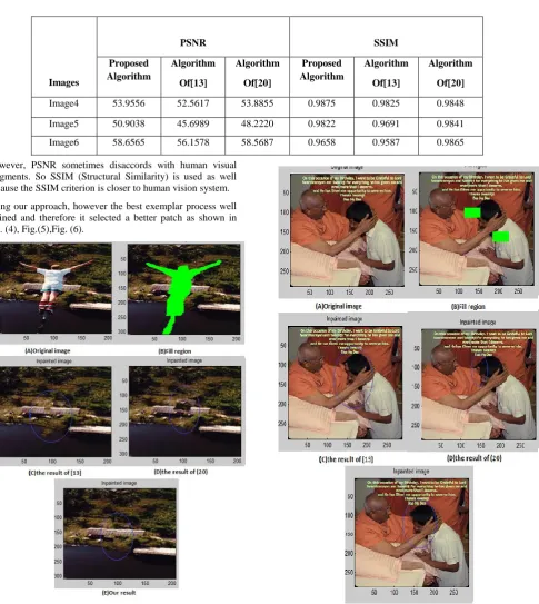
However, PSNR sometimes disaccords with human visual judgments. So SSIM (Structural Similarity) is used as well because the SSIM criterion is closer to human vision system.
Using our approach, however the best exemplar process well defined and therefore it selected a better patch as shown in Fig. (4), Fig.(5),Fig. (6).
Fig (4): TEST image1 the removal of the big object
B. Real Life Examples
[image:4.595.66.552.197.741.2]Now we present a few more examples from real life scenes which are captured by us.
Fig 5 shows examples of inpainting using our algorithm. The noise is added randomly to the image and then inpainting was applied. In this figure the structure of the head part is preserved. But the computational time for our algorithm is little longer then [13] and [20].
In all experimental, the size of patches is set to 7 by 7, 9 by 9 or 15 by 15 for all images. All the
Fig (5): TEST image2 with different algorithm Images
PSNR SSIM
Proposed Algorithm
Algorithm
Of[13]
Algorithm
Of[20]
Proposed Algorithm
Algorithm
Of[13]
Algorithm
Of[20]
Image4 53.9556 52.5617 53.8855 0.9875 0.9825 0.9848
Image5 50.9038 45.6989 48.2220 0.9822 0.9691 0.9841
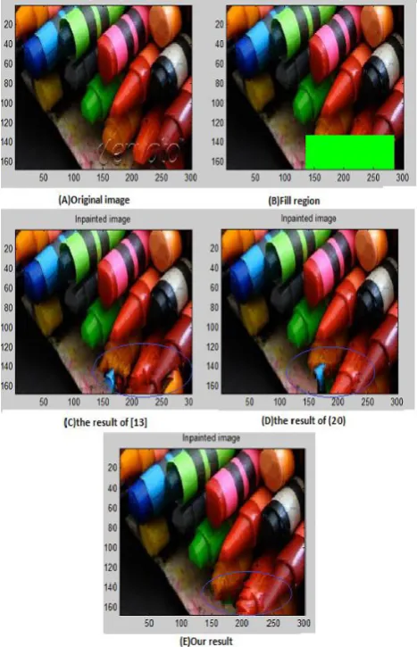
[image:4.595.307.553.212.747.2] [image:4.595.54.289.413.736.2]Fig (6): TEST image3 with different algorithm
6.
CONCLUTION AND FUTURE WORK
The method proposed by Liu kui et al.[20]includes similarity measure based only on color is insufficient to propagate accurate linear structures into the target region, and leads to garbage growing. Improved method in which image inpaint perform accurately by modified distance function a new term G representing using image gradient as similarity metric. In this method by using gradient as similarity metric accuracy of the image inpainting result can be increased. These algorithm can be used to remove object from the image in a way that it seems reasonable to human eye and provide effective image inpainting result and also enhance the performance..
7.
ACKNOWLEDGMENTS
The authors would like to thank to Shashwat Kumar , Ankit Prajapati for inspiring discussions; and G. Sapiro, M. Bertalmio, D. Capel, A. Criminisi, M.S.Ishi, Prof. Lokesh Singh, Prof. Manish Agrawal for making some of their images available.
8.
REFERENCES
[1] Ankur patel, Shashwat kumar and Ankit parajapati, “Analysis of Exemplar based Image inpainting,”International Journal of Computer Sciences and Information Technology. Vol.5 (1), 2014, pp. 800-804.
[2] Bertalmio M, Vese L, Sapiro G, Osher S. Simultaneous structure and texture image inpainting,” IEEE Transactions on Image Processing, 2003, 12, 882-889.
[3] Rane S, Sapiro G, Bertalmio M. Structure and texture filling of missing image blocks in wireless transmission and compression applications. In IEEE. Trans. Image Processing, 2002.
[4] Chan T, Shen J. Local inpainting models and TV inpainting, SIAM Journal on Applied Mathematics, 2001, 62, 1019-1043.
[5] Chan T, Shen J. Non texture inpainting by curvature-driven diffusions, Journal of Visual Communication and ImageRepresentation, 2001, 4, 436-449.
[6] Heeger DJ, Bergen JR. Pyramid-Based Texture Analysis/Synthesis. In proceedings Of ACM Conf. Comp. Graphics (Siggraph),Los Angeles, Ca, 1995, 29, 229-233.
[7] Cheng W, Hsieh C, Lin S, Wang C, Wu J. Robust algorithm for exemplar based image inpainting, in Proceedings of International Conference on Computer Graphics, Imaging and Visualization, 2005, 64-69. [8] Wong, Orchard J. A nonlocal means approach to
exemplar-based inpainting, in Proceedings of the 15th IEEE International Conference on Image Processing, 2008, 2600-2603
[9] Z. Xu and S. Jian, “Image inpainting by patch propagation using patch sparsity,” IEEE Transactions on Image Processing, Vol. 19, 2010, pp. 1153-1165. [10]Alexei A. Efros and Thomas K. Leung, “Texture
Synthesis by Non-Parametric Sampling”, IEEE International Conference on Computer Vision, 1033– 1038, 1999 .
[11]A. Wong and J. Orchard, “A nonlocal-means approach to examplar-based inpainting,” presented at the IEEE Int. Conf. Image Processing, 2008
[12]W. Cheng, C. Hsieh, S. Lin, C. Wang, and J. Wu, “Robust algorithm for exemplar-based image inpainting,” in Processing of International Conference on Computer Graphics, Imaging and Visualization, 2005, pp. 64-69.
[13]A. Criminisi, P. Pérez, and K. Toyama, “Region filling and object removal by exemplar-based image inpainting,” IEEE Trans. Image Process., vol. 13, no. 9, pp. 1200–1212, Sep. 2004.
[14]J.Wu and Q. Ruan, “Object Removal By Cross Isophotes Exemplar-based Inpainting,” Proc. 18th Intl. Conference on Pattern Recognition, vol. 3, pp. 810-813, 2006.
[15]Zhou, J. & Kelly, A. R. 2010. Image Inpainting based on local optimization. International Conference on Patteren Recognitions (ICPR).
[16]Anupam, Pulkit Goyal, Sapan Diwakar, Information Technology, IIIT Allahabad, India “Fast and Enhanced Algorithm for Exemplar Based Image Inpainting”Fourth Pacific-Rim Symposium on Image and Video Technology 2010.
[image:5.595.55.289.72.435.2][18]J. Jia and C. K. Tang, “Image repairing: Robust image synthesis by adaptive nd tensor voting,” in Proceedings of IEEE Computer Society Conference on Computer Vision Pattern Recognition, 2003, pp. 643-650
[19]Oliviera, B. Bowen, R. Mckenna, and Y.-S. Chang. Fast Digital Image Inpainting. In Proc. Of Intl. Conf. On Visualization, Imaging And Image Processing (VIIP), Page 261266, 2001.
[20]Liu Kui , Tan Jieqing , Su Benyue “ Exemplar-based Image Inpainting using Structure Tesnor” International Conference on Advanced Computer Science and Electronics Information (ICACSEI 2013).
[21]Telea,”An Image Inpainting Technique Based On The Fast Marching Method”, Journal Of Graphics Tools, Vol.9, No. 1, ACM Press 2004.
[22]A. Efors and T. Leung, “Texture synthesis by non-parametric sampling,” in Proceedings of the 17th IEEE International Conference on Computer Vision, 1999, pp. 1033-1038.
![Figure 3: Visualizations of exemplar-based inpainting process. [13] (a) Original image shows sources and target region as well as the boundary contour (b)Patch that was given the highest priority (c) Candidate patches q’ and q′′ (d) The patch q′ is fill](https://thumb-us.123doks.com/thumbv2/123dok_us/8041551.771537/2.595.56.281.486.668/figure-visualizations-exemplar-inpainting-original-boundary-priority-candidate.webp)