An Efficient Method to Avoid Hidden Node Problem in
Ad-Hoc Network
Nishu Jindal
M.Tech (CSE)Indo Global College of Engineering, Abhipur (Mohali)
Paramjeet Kaur
Asst Professor (CSE)Indo Global College of Engineering, Abhipur (Mohali)
ABSTRACT
An ad hoc network consists of various mobile nodes which are not physicals connected to each other. Ad-hoc network is temporary based network which does not rely on the infrastructure that is it is decentralized kind of network.[1] In such network, nodes communicate each other by sending data from one node to another in multi-hop mode[2]. Multi hop refer to the state when one node communicate with its immediate node and the data has to travel through many intermediate nodes from source to destination. Generally there are two problems associated with communication one is hidden node problem other one is exposed node problem. In general scenario when two nodes send data to the same node at same then collision occurs at that node, This is known as hidden node problem.[3] Hidden node problem can be avoided by RTS/CTS mechanism.[4] To make data secure from collision i.e to prevent hidden node problem and also to reduce delay time that occurs when nodes goes to waiting state during RTS/CTS handshake if the communication occurs before the CTS timer, integrating the concept of RTR with RTS/CTS. Apart from the introduction of RTR, in this paper there are other parameters such as data size and distance preference which will further help to define the priorities for the transfer of data.
General Terms
CSMA, Adhoc Network, Exposed node,
Keywords
Hidden Node, RTS/CTS Mechanism, RTR
1.
INTRODUCTION
An assembly of two or more devices equipped with wireless communications and networking competence is known as ad hoc wireless network. Communication through these devices takes place with the node immediately present in their radio range. For the nodes which are not in the communication range an intermediate node is used to relay or forward the packet from the source toward the destination. An ad hoc wireless network is self-organizing and adaptive. This means that a formed network can be de-formed on-the-fly without the need for any system administration.[5] The term "ad hoc" tends to indicate "can take different forms" and "can be mobile, standalone, or networked." Ad hoc nodes or devices should be able to perform the necessary handshaking by detecting the presence of other such devices and to allow communications and the sharing of information and services. The computation, storage, and communications capabilities of such devices will vary immensely as ad hoc wireless devices can take different forms (for example, palmtop, laptop, Internet mobile phone, etc.).[6]
2.
RTS/CTS HANDSHAKING
Fig 1: Hidden node problem
In Fig 1 Node A and Node C are sending the data to Node B at same point of time which will led to the collision at node B. node B will become hidden node to both A and B. Data Collisions which occur due to hidden node problem can be reduced by the introduction of RTS/CTS (Request to Send / Clear to Send) mechanism used by the 802.11 wireless networking.[7] Although it solves the hidden node problem but eventually it introduces another exposed node problem. This mechanism is also called RTS/CTS four way handshaking. CSMA (Carrier sense multiple access) is an another mechanism used by 802.11 to sense if there any other transmission is going on.[8]If a carrier is found to be busy, the station waits for the transmission in progress to finish before starting its own transmission. If channel is found idle, sender sends RTS to node it wants to send data, RTS receiving node replies with CTS. The 802.11 standard addressed this problem and suggested that the transmitter should, prior to any transmission, reserve his communication range as well as the receiver range by using ready to transmit / clear to transmit (RTS/CTS) handshaking. The whole idea is to include the ready to send and clear to send messages to avoid collision. In case that A (transmitter) has a long message to send to B (receiver), the procedure will be as follows:
It send RTS message indicating the transmitter address (A), intended receiver address (B) and the expected time required. All the nodes which are in the transmission range [9] of sender sense this communication and block themselves for any other communication.
The receiver (B) broadcast CTS to all nodes in its transmission indicating the CTS-transmitter address (B), CTS-receiver address (A) range and starts the CTS timer. The hidden node (C) will hear the CTS message, know about the medium reservation and wait for the time reservation before resuming contention for the channel.
44 communication gets over before the time expires. Due to
which the delay occurs.[3]
3.
INTEGRATION
OF
RTR
WITH
[image:2.595.57.281.97.208.2]RTS/CTS
Fig 2: Integration of RTS/CTS with RTR
To avoid this waiting time of all other nodes which received the CTS from receiver and wait for communication in RTS/CTS handshaking till CTS timer expires; a new mechanism is integrated with this mechanism known as RTS/CTS with RTR (Ready to Receive). This message is broadcasted to all the nodes by receiver node (B) means now it is free to communicate with the other nodes). A novel protocol is designed especially for safety-related applications. It also integrates other non-safety applications with a new multi-mode feature. The new protocol is presented as a series of four successive steps starting from the Smart Broadcasting Protocol. These steps are:
Reversing the order of priority Headway-based segmentation
Non T uniform segmentation based on naturalistic model of driver’s reactions
Application adaptive multi-mode scheme.
[image:2.595.323.562.347.738.2]4. SIMULATION SENARIO
Fig 3: Showing integration of RTS/CTS with RTR to show preferences
In this paper integrating the concept of RTR with RTS/CTS.As we know nodes communicate to each other by sending RTS/CTS control packet. Let us consider in fig 3 Node A wants to communicate with Node B. Node A sends RTS to Node B and Node B reply with CTS which is broadcasted to all the nodes within its range i.e. Node C. Node C after receiving CTS do not interfere in the communication between A and B Nodes. As I have taken assumption that if communication ends before the expected time sent by CTS then the node (Node B) which was previously communicating will send RTR signal to all other nodes which are in its range and other nodes will start sending data to RTR sending node.
When RTR is broadcasted to other nodes, these nodes will communicate or send data according to two techniques.
According to distance According to data size
Earlier when RTR was used to reduce the defness problem,[10] RTR from receiver node was send in circular format from node to node to resume the communication. This protocol of sending circular RTR is known as Circular RTR DMAC.[11] During this the receiver send the RTR to all the nodes in its range one by one. For example in the above fig 4, B will send the RTR message to D first. Then after their communication over B will send the RTR message to C and same is the case with E. Now during this, if in case C has lesser data as compared to D, it has to wait until the communication between B & D gets over, which will lead to a further delay.
To reduce this, the concept of variable preferences is introduced, in which RTR message would be broadcasted to all the nodes simultaneously. After which the communication will start on the basis of our operating system concept i.e. SJF (shortest job first) as per the given distance and data preferences.
Fig 4: Flow Chart
START
SENDER SENDS RTS TO RECEIVER
RECEIVER SENDS CTS TO ALL THE NODES AND STARTS CTS TIMER
SENDER SENDS DATA TO RECEIVER
IF COMMUNICATION ENDS BEFORE EXPIRATION OF CTS
TIMER
RECEIVER WILL SEND RTR TO NODES
RECEIVED CTS
NODES WILL SEND DATA TO RECEIVER ACC TO DISTANCE OR
TIME PREFERENCE
END
NO [image:2.595.54.274.383.590.2]5. EXPERIMENTAL RESULTS
Fig 5: Deployment of nodes
In the above Fig 5 a network with 70 nodes is designed in which node 61 is the sender node and node 11 is the receiver node. The circle marked in “RED” defines the range of sender and “GREEN” defines the range of receiver. All the nodes in red circle will hear the RTS and will not be able to communicate with any other node. Receiver will broadcast CTS to all the nodes in its range (node no- 5, 53, 57, 32 and 30) and start the CTS timer. If the communication between node 61 & 11 gets over before the expiration of CTS timer, node 11 will send RTR to all the nodes in its range. Now nodes will start sending the data as per the defined preferences.
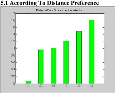
5.1 According To Distance Preference
Fig 6: Data size of each node
When CTS is broadcasted to other nodes, these nodes goes to the waiting state , so if communication done before the approximate timer of the CTS . Then the receiving node send RTR to other nodes to reduce delay time. This RTR is broadcasted to all the nodes and nodes will communicate or send according to distance preference .This means that node which is at shorter distance will send data to that Node so a kind of Queue is developed and all nodes will communicate according to this queue. That having smallest distance will be at the top of queue will be added at top position. And that topmost node will communicate first or send data first.
[image:3.595.315.542.71.253.2]5.2 According To Data Size Preference
Fig 7: Time taken for transfer of data
Simillarly when RTR is broadcasted to all the nodes and nodes will communicate or send data according to data size preference .This means that node which has smaller data size will send data to that Node so a kind of Queue is developed and all nodes will communicate according to this queue. That having smallest data size will be at the top of queue will be added at top position. And that topmost node will communicate first or send data first. So Node which smallest in data size will execute first.
In case the communication between sender and receiver finishes before the expiry of CTS timer, all the nodes (which were not liable to communicate with the receiver node) in transmission range of sender starts sending data on receiving RTR from receiving node based on the preferences (data size/time). So the time these nodes had to wait for expiration of CTS timer to start communication with receiver node has been utilized for the communication. As now delay time is reduced in the network due to integration of RTS/CTS and RTR so throughput of the network is also improved. We can also see from throughput graph that performance or throughput has been improved. In case of RTR total time taken by nodes (node no 5, 53, 57, 32, 30) to send the data is 32 sec as per the Fig 7. In case of RTS/CTS mechanism time taken by sender to send the data to receiver is 4sec but next communication will start only after the expiration of CTS timer which is of 25sec, which shows a considerable time delay.
5.3 Comparison between RTS/CTS &
RTS/CTS with RTR
[image:3.595.53.281.420.602.2]46 Fig 8: Time Comparision
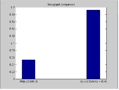
[image:4.595.54.252.313.463.2]Following graphs shows the throughput of network while transferring the data in case of RTR and CTS/RTS. Throughput in case of RTR will be the difference of both the communication cases of CTS/RTS and CTS/RTS+RTR.
Fig 9: Throughput Comparison
Following graphs shows the energy taken by the sender nodes to send the data after receiving RTR and energy taken between sender and receiver node those initiate the communication after receiving the CTS. Similarly energy in case of RTR will be the difference of both the communication cases of CTS/RTS and CTS/RTS+RTR.
Fig 10: Energy Comparison
6. CONCLUSION
It leads to reduction of delay time occurs during RTS/CTS if the communication occurs before the expiration of CTS timer. And also due to reduction in delay time and Throughput of the network also increased .Hence integration of RTS/CTS and RTR is more beneficial and improved technique as compared to RTS/CTS technique. As in wireless network communication where delay and throughput plays important role in the performance of the network. So by implementing RTS/CTS integration we improve both the things delay and throughput. By using this mechanism in future we can get good results.
7. ACKNOWLEDGMENTS
I would like to place on record my deep sense of gratitude to Ms. Paramjeet Kaur (Asst Professor) Dept. of COMPUTER SCIENCE, IGCE, Abhipur, India for his generous guidance, help and useful suggestions.
I also wish to extend my thanks to Mr. Bhupinder Singh, H.O.D of Computer Science Department of IGCE, Abhipur and all faculty member of CSE department for attending my seminars and for their insightful comments and constructive suggestions to improve the quality of this research work.
I am extremely thankful to Dr. Promila Kaushal Principal, IGCE Abhipur, for providing me infrastructural facilities to work in, without which this work would not have been possible.
8. REFERENCES
[1] Ashikarrehman and Pawel Gburzynski Department of Computing Science University of Alberta Edmonton, Alberta, Canada, T6G 2E8 “Hidden problems with hidden node problem” in 2006.
[2] C.-K. Toh, V. Vassiliou, G. Guichal, C.-H. Shih, “March: a medium access control protocol for multihop wireless ad hoc networks,” in Proc. of 21st Century Military Communications Conference, pp. 512-516, 2000.
[3] Viral V. Kapadia, Sudarshan N. Patel and Rutvij H. Jhaveri “ Comparative study of Hidden node problem and solution using different techniques and protocols” journal of computing , volume 2 , issue 3, March 2010.
[4] Arunajayasurya ,Sylvie perreau, Arekdadej, Steven Gordan institute of telecommunication and research .university of south Australia “Hidden vs. Exposed Terminal Problem in Ad hoc Networks “ in 2004
[5] Rajeshwar Singh, Dharmendra K Singh, Lalan Kumar Int. J. Advanced Networking and Applications 2011 “Performance Evaluation of DSR and DSDV Routing Protocols for Wireless Ad Hoc Networks
[6] Vaduvur Bharghavan Department of Electrical and Computer Science Engineering University of California. “MACAW(A media access protocol for wireless LAN)” in 1994.
[7] Mostefa Fatima Zohra, Mekkakiamaaza Zoulikha. Khelifa “Techniques of detection of the hidden node in wireless ad-hoc network” in 2011.
[image:4.595.63.272.570.724.2][9] Sunil Kumar, Vineet S. Raghavan, Jing Deng 2004 “Medium Access Control protocols for ad hoc wireless networks: a survey”.
[10]Hrishikesh Gossain, Carlos Cordeiro, Dharma P. Agrawa, 2005, “Minimizing the Effect of Deafness and Hidden Terminal Problem in Wireless Ad Hoc Networks using Directional Antennas
[11]Huang Lu, Jie Li, and Zhongping Dong, Yusheng Ji 2011 Seventh International Conference on Mobile Ad-hoc and
Sensor Networks “CRDMAC: An Effective Circular RTR Directional MAC Protocol for Wireless Ad Hoc Networks”.