Analysis
of
Header
Compression
Techniques
for
Networks:
A
Review
Manish
Raj
Shivare
School of Information Technology UTD, RGPV, MP, India
Yogendra P. S.Maravi
School of Information Technology UTD, RGPV, MP, India
Sanjeev Sharma,
Ph.DSchool of Information Technology UTD, RGPV, MP, India
ABSTRACT
Due to the rapid evolution of internet and wireless networks a need of the efficient transmission over the channels. Efficiency is extremely vital once the value of transmission is extremely high. Example, during a wireless network radio bandwidth is restricted thus cost is increasing in payload transmission. Header compression will play a vital role in payload transmission. The result of compression is that there's less information to send across the link, which in effect, will increase the bandwidth of the link. The contribution of this paper is that the proposed uses of Header compression scheme for TCP/IP stream.
Keywords
Header Compression Schemes, CRTP Compression, VJHC Compression, IPHC Compression, ROHC Compression
1.
INTRODUCTION
Due to expeditious growth in wireless network demand of the high radio bandwidth is generated. Moreover IPv6 [1] is being spread in next generation networks resulting size of header increased from 32- bit (in ipv4) to 128-bit. Today’s network platform entirely based on the TCP/IP architecture [2]. They're using TCP and IP protocol as a base protocol. In a noisy channel encapsulation method of TCP/IP ruins a substantial part of radio link bandwidth for transmission of control information (like a header), the result of this retransmission is required: since this a lot of bandwidth is wastage. Bandwidth is generally costlier and resources are limited for the wireless network. In TCP/IP architecture requirement of two functions header compression and header decompression, they're positioned just under the Network layer of a node in a Network [3].
The most important schemes for header compression in computer network on TCP/ IP architecture proposed by IETF. The most effective use of data compression takes place when the characteristics of data packets are well known, depending on a changeable and statistical characteristic of the actual packet format. In this paper, the effects of standard compression algorithms are analyzed. Van Jacobson Header Compression (VJHC) and Robust Header Compression (ROHC) is a standardized method to compress the UDP, IP, RTP and TCP headers of INTERNET packets. The main aim of CRTP, VJHC and ROHC is to improve link efficiency for network. In this case efficiency justified in terms of reduced bandwidth.
Due to compression a drawback arises that for decompressing the packet, decompressor requires information about the way which the compression performed referred as a “context”. For correct decompression, this context information required
However, if the segment is lost and corrupted then decompressor declares that decompression is invalid this is detected by the TCP checksum. Following this, all receiving packets after the lost corrupted packet will decompress improperly, due to this packets are discarded at the receiver side. The result of this, the sender will not receive acknowledgement, therefore the self-clocking of the transmission is broken. The effect of this, the sender is reach into the timeout state, thus TCP/IP sender eventually retransmits the original corrupted or lost packet in uncompressed form for recovering.
In this review paper we study different Header compression schemes and their performance over a radio bandwidth.
2.
HEADER FIELD REDUNDANCY
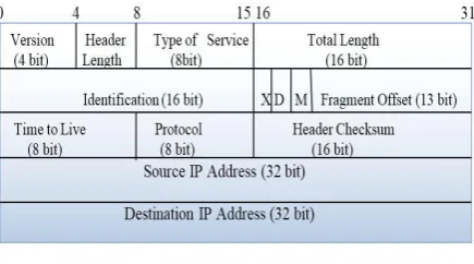
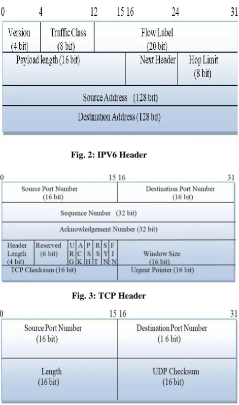
[image:1.595.320.538.566.687.2]One way to optimize bandwidth usage is to reduce the amount of redundant protocol operational overhead transmitted with every packet which is belonging to the same packet stream, the version, flow label, next header, source address, and destination address fields are identical. In the IPV4, IPV6, UDP and TCP header fields remain static between consecutive packets belonging to the same packet stream. In UDP, two sequential packets in the same stream will have the same source and destination port fields. However, the checksum field is random and varies with every packet. Similar to UDP, TCP headers include not only static and random fields, but also dynamic fields (i.e., TCP sequence numbers) that change incrementally between two consecutive packets. Header compression schemes such as CRTP, IPHC and ROHC exploit these protocol header field redundancies, thus enabling more efficient communication. Redundancy in IPV4, IPV6, TCP and UDP is specified by Figure 1, 2, 3 and 4.
Fig. 2: IPV6 Header
[image:2.595.320.540.427.490.2]Fig. 3: TCP Header
Fig. 4: UDP Header
3.
HEADER COMPRESSION SCHEMES
The problem with the performance of the IP protocol over a low bandwidth link has been studied with the Thin-wire protocol specified by Faber and Delp [4]. Header compression is a mechanism that compresses the IP header or TCP header in a packet before the packet is transmitted. There are different types of header based redundancy in the protocol which is specified by IETF, as IP Header Compression, Compressing IP/UDP/RTP Headers for Low-Speed Serial Links [5] and Enhanced Compressed RTP (CRTP) for Links with High Delay, Packet Loss and Reordering [6]. Previous studies have demonstrated that the performance of these protocols is still quite poor in wireless links. In this paper we study some types of header compression mechanism.
3.1
CRTP Header Compression
The Real Time Protocol (RTP) is the Internet Standard for conveying media streams between interactive participants [7]. RTP provides end-to-end network transport functions for applications that support audio, video or multimedia over unicast or multicast services. Compressed RTP Header
(CRTP) scheme is supported on serial interfaces using Frame Relay, HDLC, or PPP encapsulation. The combination of the UDP, IP and RTP control information adds up to a significant overhead for small media samples, particularly over low speed links. An Internet Protocol Datagram has a 20 byte header, while the UDP header is 8 bytes (source and destination port address, plus length and checksum field). The RTP header adds another 12 bytes into this, making a total of 40 bytes of control for a single sample.
3.1.1
CRTP Operation
RTP includes a data portion and a header portion. First, the data portion of RTP is a thin protocol that provides support for the real-time properties of applications, like continuous multimedia, including loss detection, timing reconstruction and content identification. Second, the header portion of RTP is considerably larger than the data portion of the header. The header portion consists of the IP segment, the User Datagram Protocol (UDP) segment, and the RTP segment. To avoid the unnecessary consumption of available bandwidth, RTP header compression work on a link-by-link basis.
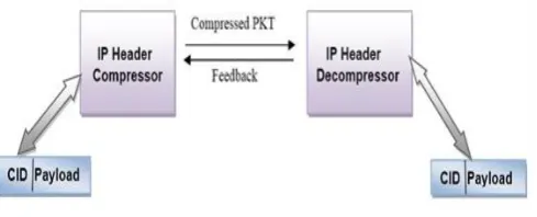
RTP header compression protocol compresses the combined IP, UDP, and RTP segments (RTP Header) 40 bytes into 2-4 bytes in an RTP packet [8]. Below Figure 5 illustrates this by a block diagram. In this case, we assume that the RTP packet contains 20-160 bytes payload. RTP header compression identifies the RTP traffic and then compresses the IP header portion of the RTP packet. The header portion consists of an IP segment, a UDP segment, and an RTP segment. Figure 5 illustrates that total IP header (40+160 bytes) packet after an RTP compression become small packet (4+160 bytes). Therefore, we reduce the 40-byte header into a 2-4 byte header, 36 bytes extra overhead reduced.
Fig. 5: RTP Header compression
CRTP creates a report of transmission [9]. This report contains a convey information concerning packet losses. This contains not only as health reports of packets, but additionally contains information about compression level for sources capable of adapting. The result of the RTP header compression is a major reduction in redundancy in terms of packet compression because several fields in the header change in every packet, the inequality from packet to packet is usually constant. The decompressor is capable to reconstruct the original header without any loss of information. RTP header compression is beneficial when the RTP payload size is very small, as an example, for compressed audio payloads of 20 to 50 bytes.
3.2
VJHC Header Compression
3.2.1
VJHC Operation Mode
The algorithm first classifies packets into individual flows (i.e. Packets that share the identical set of {IP addresses, IP protocol type, and TCP port numbers}) [10]. State (a context) is n created for each flow and a Context ID (CID) assigned to identify the flow at the compressor and decompressor. The sender then omits the fields in the header that remain unchanged between successive packets in an IP flow (these may be deduced by using the CID in each packet to refer to the context state at the decompressor).
[image:3.595.309.554.261.360.2]VJHC compression reduces the redundancy within the TCP/IP header field specified in Figure 1and 3. Within an IP flow, more than half of the field are unchanged between successive packets. The “total length” and “identification” field are expected to be handled by link framing protocols. “IP checksum” can also re-calculate at the receiver [10]. By suppressing these fields at the compressor and restoring them at the decompressor, VJHC can significantly improve transmission efficiency for the packet header. Figure 6 specifies operation of VJHC compression.
Fig. 6: VJHC Header Compressions
Furthermore, the remaining changing fields do not frequently change at the same time [10]. The remaining fields usually change only by a small amount in successive packets. VJHC relies on two types of error detection: A CRC at the data link layer (to detect corruption of the compressed packet) and the TCP checksum at the transport layer (to detect corruption in the compressed packet). When errors are detected, the receiver discards the erroneous packet. This creates another problem within the decompression process. Since the differential compression techniques are applied, the receiver also loses the context state. The next following packet after the discarded packet cannot therefore be decompressed correctly. It must also be discarded. All subsequent packets will therefore be discarded until the next synchronization (i.e. an uncompressed packet is received, restoring the context state). To overcome this error propagation, receiver ought to use the differential sequence number change from the incoming compressed packet to the sequence number of the last correctly received packet, and generate a correct sequence number for the packet after discarding the packet. Errors in the value of the TCP checksum errors of packets received by the destination end host must also be considered. When the end host fails to receive TCP data segments (forward path), no TCP acknowledgement is sent. The senders eventually suffers a TCP timeout, and resend the missing segment(s), these also trigger the compressor to resynchronize the context state.
3.3
IP Header Compressions
The Internet Protocol together with transport protocols like TCP or UDP and optional application protocols like RTP are described as a packet header. The IP header contains source and destination addresses, protocol identifiers, sequence numbers, error checks etc. Internet Protocol Header Compression [11] relies on the characteristic that many packet Header fields remain constant (or doesn’t frequently change)
Taking advantage of this redundant information, IPHC defines a compressor to send packets with partial or no headers, and a decompressor to deduce the unsent packet header fields. The reduction in the amount of transmitted headers (i.e. overhead) leads to increased user throughput.
3.3.1
IPHC Operation
[image:3.595.55.287.297.358.2]IPHC operating is comparable as VJHC scheme. The most important difference between IPHC and VJHC is that IPHC compresses only the IP header. IPHC supports any transport protocol or tunnel encapsulation also ECN [12] and IPv6 [13]. The compressor establishes static header fields as constants, and associates them with a context (CID). If context synchronization is lost, i.e. one of static header fields change, individual fields (or the entire full header) will be transmitted to re-establish (refresh) the context. Figure 7 illustrates the IPHC operation.
Fig. 7: IP Header Compression Mechanism
3.3.2
IPHC Synchronization Recovery
IPHC implementation includes recovery mechanisms, applied when context synchronization is lost between the compressor and decompressor [12]. Synchronization lost implies that the packet is lost or Reordering of packet in a current context. Context resynchronization handled in different ways, depending on the environment condition where compression is taking place:
For compression between intermediate hops of a TCP connection, when the packet is lost the compressor recognize the TCP packet header lost and starts retransmission. If a retransmission is taking place, the compressor may require sending a full header to update the decompressor context.
For compression between intermediate hops of a UDP path, the compressor receives no feedback from the decompressor. Therefore, a generation identifier transmitted with each compressed header, aiding the decompressor in identifying old contexts.
A context state packet, sent on bidirectional links from the decompressor to the compressor, specifically indicates the CIDs encountering invalid decompression. After receiving of the packet, the compressor correspondingly marks the listed CIDs as invalid, then compressor sending a full header for reestablishing context.
Fig. 8: IPHC Compression gain [14]
3.4
ROHC Compression
The Robust Header Compression scheme [15] developed by the IETF’s ROHC working group for RTP/UDP/IP, UDP/IP, and ESP/IP packet headers. Major benefits of ROHC compression improved performance over IPHC, and CRTP in high BER and high RTT wireless links [16]. A key feature is that the ROHC framework is that new protocols can be added without the need to design a completely new compression protocol. ROHC functioning same as IPHC, ROHC exploits header field redundancies, and establishes the context between source and destination hops. The major difference between ROHC and IPHC is the option to instantiate a feedback mechanism from the decompressor to the compressor [17]. A disadvantage of ROHC is a complicated technique, absorbing all the existing compression techniques, and adding a more sophisticated mechanism to achieve robustness and reliability.
3.4.1
ROHC Functioning
ROHC functionality specified by two finite state machines (FSMs): one placed on the compressor end and one on the decompressor end [17].
3.4.1.1
Compressor FSM
It consists of Initialization & Refresh (IR), First Order (FO) and Second Order (SO) states (or compression level). Figure 9 specifies compressor state and transitions.
The IR state (Level 1 compression) is liable for initializing the static parts (source address, destination address, etc.) of the context. Headers sent from the compression end are in uncompressed form.
The FO state (Level 2 compression) signifies partial context established between decompressor and compressor. The FO state provides the means for efficient communication of anomalies in the packet stream. Therefore, headers sent by the compressor are only partially compressed.
[image:4.595.321.537.76.150.2] The SO compressor state (Level 3 compression) specifies a link with optimum header compression. Full context is established between decompressor and compressor, as the decompressor has enough information to understand most header patterns.
Fig. 9: ROHC Compressor Finite State Machine
The size of the compressed header depends on the compression level and the header information required by the decompressor [18]. In the first level of compression IR, the header size is between 48 to 130 bytes; In the First Order, the compressed headers have a size between 3 to 84 bytes. In the last compression level (SO), the header is compressed up to just one byte.
3.4.1.2
Decompressor FSM
It consists of No Context (NO), Static Context (SC) and Full Context (FC) states.
The first state is No Context (NC), the decompressor stays initially where there is no context and reached it when the context is lost. In this state only the IR header, format packets are decompressed and any other header format packet is dropped. In other words, NC indicates that the decompressor has yet to successfully decompress a compressed header.
The decompressor changes to Full Context (FC) state when correct decompression (successful) of a header takes place (verified by CRC) or if the context is established.
The Static Context (SC) state is not reached except when there is an error and the dynamic part of the header is lost.
Depending on the success of the subsequent decompressions of static and dynamic header fields, the decompressor will transit back to the SC and NC states. Figure 10 specifies the decompressor states and transitions [18].
[image:4.595.316.559.556.746.2]3.4.2
ROHC Context
ROHC uses a context maintained between compressor and decompressor to store the information about the header stream. This context contains the last correct update of the original header and the redundant information within the stream. This context is kept by compressor and decompressor in order to ensure the robustness of the mechanism. Each time a value in the context changes, the context is updated [18]. If the context is lost due to transmission errors then there is no synchronization between the compressor and the decompressor.
The decompressor then can request for the context update through the possible use of acknowledgements. Each flow in a channel has its context, which is identified by a CID (Context Identifier) which is a number that differentiate the flows in a channel, and the context in compressor and decompressor. ROHC header context specifies by figure 11 (a) and figure 11 (b) [18].
Fig. 11: (a) IR & IR-DYN Packets (b) Level 0, 1 and 2 Packets
3.4.3
ROHC Operation Mode
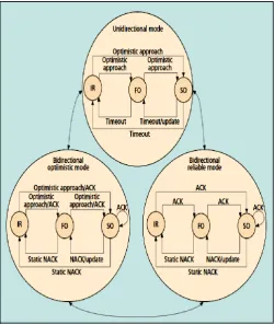
ROHC defines three operation modes, they are unidirectional (U-mode), Bidirectional Optimistic (O-mode) and Bidirectional Reliable (R-mode). The ROHC operational mode is handled by FSM. This high-level FSM consists of three states [17]:
All ROHC operations start from U-mode, and then may transit to O-mode or R-mode depending on the feedback information. Unidirectional mode (U-mode) specifies compression over a unidirectional link in which packets sent strictly from the compressor to the decompressor. Depending on the decompressor’s knowledge of header fields/patterns (as presumed by the compressor), the compressor undergoes an upward transition from the IR state to the FO state, or “optimistically” transitions to the SO state. The compressor’s downward state transitions performed due to periodic timeouts and irregularities in header-field patterns. Downward transitions based on periodic timeouts (i.e., compressor transition from the SO state to the FO and IR states periodically to send a full header) are required since the compressor receives no context synchronization feedback from the decompressor.
Bidirectional optimistic mode (O-mode) specifies a ROHC scheme over a bidirectional link between the compressor and decompressor. In this mode, a feedback channel is present from the decompressor to the compressor. The decompressor uses the feedback mechanism only for indicating when improper decompression has occurred (i.e., error communication) and acknowledgment of significant context updates. O-mode’s purpose is to maximize header compression and incorporate minimal usage of the feedback channel.
[image:5.595.56.278.270.447.2] Bidirectional reliable mode (R-mode) specifies a ROHC scheme over a bidirectional link between the compressor and decompressor. Compared to O-mode, R-mode establishes a more dependable ROHC scheme between the compressor and decompressor. R-mode aims to maximize robustness in lost/damaged packet scenarios, resulting in a minimization of context invalidation between ends. This is, achieved with frequent usage of the feedback channel and stricter logic at both ends. However, this reliability comes at a cost, as the magnitude of compression used in R-mode is less than the amount achieved by O-mode.
Figure 12 illustrates the operation mode of ROHC FSM. Note that in O-mode and R-mode, state transitions are a function of the feedback received from the decompressor; in U-mode transitions are based on timers (i.e., to ensure context synchronization).
[image:5.595.316.567.402.700.2]3.5
ADVANTAGES AND DISADVANTAGES
Table 1advantages AND Disadvantages
Compression Methods
Advantages Disadvantages
CRTP
RTP header compression supports on serial interfaces using Frame Relay, HDLC, or PPP encapsulation.
Header supported- IPv4, IPv6
(including extension headers), Minimal Encapsulation header, Tunneled IP headers, UDP, RTP
RTP header compression provides support for real-time conferencing of groups of any size within the Internet.
It is reduce 40-byte header into a 2-4 byte header.
Periodically, uncompressed header must be sent to identify correct state both sides.
CRTP not recommended on any high interface because any bandwidth savings achieved with CRTP (may be offset) increase in CPU utilization on the router.
CRTP performs very poorly on channels with high packet loss and long delay.
VJHC
Van Jacobson compression reduces the normal 40-byte TCP/IP packet headers down to 3-4 bytes in the average case.
TCP and IPV4 Header support.
VJHC benefits the transmission and brings a higher throughput when the BER (Bit Error Rate) is not very high (around 10-6 or less).
VJHC processed IP + TCP header so complexity reduces [20].
When BER increases, VJHC does not bring significant advantages for either channel rate at a very high BER (around 10-5) [19].
VJHC suffered from a loss of synchronization (when not used with a reliable link protocol) and the combined compression of the TCP and IPv4 headers.
IPHC
Support compression of TCP/IP, UDP/IP.
Minimal implementation complexity
IPHC is independent of the transport layer protocols.
Reduction in packet loss.
Better interactive response time.
Delayed context
resynchronization over long RTT.
IPHC is only half as efficient as VJHC for TCP packets.
Implementation requires processing and memory resources.
ROHC
Developed for header compression over high BER links.
Improved encoding scheme for compression of dynamically changing header fields.
Adjustment mechanisms for quick context resynchronization.
More complex implementation requires significant processing and memory resources.
5.
CONCLUSION
This survey paper presents comparative study of different type of header compression techniques. CRTP header compression provides support for real-time video conferencing of groups of any size among the Internet. But CRTP performs very poorly on channels with high packet loss and long delay. VJHC benefits the transmission and brings a higher throughput when the BER is not very high. But drawback of the VJHC compression technique is that it is suffering from a loss of synchronization and when BER increases, it does not bring significant advantages for either channel rate (At a very high BER (around 10-5)). VJHC does not support recent changes to IP (e.g. ECN), or TCP (e.g. SACK, ECN, TS option, LFN). IPHC header compression support IPv4 (including options and fragments), IPv6 (including extension headers), Minimal Encapsulation header, Tunneled IP headers, TCP (including options), UDP. In IPHC Packet loss rate low and better interactive response time. IPHC is only half as efficient as VJHC for TCP packets.
ROHC header compression has a quick context resynchronization. Window-based Least Significant Bit provides facility to compression of dynamically changing header fields. It is provided compression on high BER as compare to VJHC.
In the future, it can be expected that header compression techniques based on the ROHC framework techniques will be able to achieve a reasonable compression ratio on the different type of wireless network.
6.
REFERENCES
[1] S. Deering and R. Hinden,”Internet Protocol Version 6 (IPv6) Specification”, RFC 1883, 1995.
[2] T. Socolofsky and C. Kal, “A TCP/IP Tutorial”, RFC 1180,1991
[3] P. Camarda, S. Petrizzelli,”Performance Analysis of a
New Header Compression Scheme For \TCP Streams In IP Based Wireless Networks”, IEEE,2002,276-281. [4] David J. Farber, Gary S. Delp ,Thomas M. Conte “A
Thin wire Protocol for connecting personal computers to the INTERNET” RFC914 ,1984
[5] S. Casner , V. Jacobson “Compressing IP/UDP/RTP Headers for Low-Speed Serial Links” RFC2508,1999 [6] T. Koren, S. Casner, J. Geevarghese, B. Thompson, P.
Ruddy ”Enhanced Compressed RTP (CRTP) for Links with High Delay, Packet Loss and Reordering” RFC3545,2003
[7] H. Schulzrinne, S. Casner, R. Frederick, V. Jacobson “RTP: A Transport Protocol for Real-Time Applications” RFC3550, 2003
[8] “Configuring TCP Header Compression”, Cisco Systems, May 2007.
[9] Crowcroft, Jon, Mark Handley, and Ian Wakeman. “Internetworking multimedia” CRC Press, 1999. [10]Ching Shen Tye and Dr. G. Fairhurst “A Review of IP
Packet Compression Techniques”, PGNet, 2003
[image:7.595.33.568.132.402.2]4.
COMPARISON BETWEEN HEADER COMPRESSION SCHEMES
Table 2 Comparison between Schemes
CRTP VJHC IPHC ROHC
Minimum Compressed
Header Size 2 bytes 2 bytes 2 bytes 1 byte
Type of Link Dial-up and wireless Dial-up Dial-up and wireless Wireless
BER Low to medium Low Low to medium High
RTT Short to medium Short Short to medium Long
Encoding Delta Encoding Delta Encoding Delta Encoding Window-based Least
Significant Bit
Feedback Yes No Yes Yes
Application Area Satellite, WAN and dial-up networks
WAN and dial-up Network
Cellular, satellite, WAN and dial-up networks
[11]M. Degermark, B. Nordgren, S. Pink “IP HEADER COMPRESSION”, RFC2507,1999
[12]K. Ramakrishnan, S. Floyd, D. Black ” The Addition of Explicit Congestion Notification (ECN) to IP”, RFC2481, 2001
[13]S. Deering, R. Hinden “Internet Protocol, Version 6 (IPv6)specification”, RFC2460,1998
[14]“An introduction to IP header compression”, Effnet AB WHITE PAPER Library, FEB 2004
[15]L-E. Jonsson, G. Pelletier,K. Sandlund “The RObust Header Compression (ROHC) Framework”, RFC4995, July 2007
[16]C. Bormann, Ed., “Robust Header Compression (ROHC),”RFC 3095, June 2001
[17]Emre Ertekin and Chris Christou, Booz Allen Hamilton,” Internet Protocol Header Compression, Robust Header
Compression and Their Applicability in the Global Information Grid” IEEE Communications Magazine, November 2004, 106-116.
[18]Alain Couvreur, Louis-Marie Le Ny, Ana Minaburo, Gerardo Rubinoy, Bruno Sericolay,and Laurent Toutain “Performance Analysis of a Header Compression Protocol: The ROHC Unidirectional Mode” ENST Bretagne.
[19]Ruhai Wang, Stephen Horan “Impact of Van Jacobson Header Compression on TCP/IP Throughput Performance over Lossy Space Channels” IEEE Transactions On Aerospace And Electronic Systems Vol. 41, No. 2 April 2005,681-692.