HONEYWELL
PRU7070/7071
&
PRU7075/7076
PRINTERS
PRU7070/7071
&
PRU7075/7076
Printers Handbook
SUBJECT
Description and Operation of the PRU7070/7071 and the PRU7075/7076 Printers
SPECIAL INSTRUCTIONS
This manual supersedes CY93-00, dated August 1982. Change bars in the margins indicate new or changed information.
The following notice is provided in accordance with the United States Federal Communications Commission's (FCC)re lations.
Warning: This equipment generates, uses, and can radiate radio frequency energy and if not installed and used in accordance with the instructions manual, may cause interference to radio communications. It has been tested and found to comply with the limits for a Class A computing device pursuant to Subpart J of Part 15 of FCC Rules, which are designed to provide reasonable protection against such interference when operated in a commercial environment. Opera-tion of this equipment in a residential area is likely to cause interference in which case the user at his own expense will be required to take whatever measures may be required to correct the interference.
This equipment is subject to and will comply with the appropriate FCC Rules prior to final delivery.
ORDER NUMBER
About This Manual
This manual explains the operation of the PRU7070/7071 and PRU7075/7076 printers. Before using the printers, Honeywell recommends that you read this manual completely, especially Appendix B which explains the set-up procedures for the printers.
Section 1 gives a brief description of the printers, outlining their features and dif-ferences. An explanation of the main controls and indicators is found in Section 2. Operating procedures, complete with labeled photos, are detailed in Section 3. Section 4 provides programming information and details the commands for the printers. A functional description of the printers is given in Section 5.
The Appendixes describe the technical aspects of the printers and their operation. Appendix A explains the internal configuration controls. Appendix B discusses shipping procedures, installation, maintenance, cable connection, andjumper positioning. Printer specifications are given in Appendix C. Table C-2 in Appendix C should be referenced before ordering paper or ribbons for the printers. The correct media must be used to ensure satisfactory performance. Appendix D presents the ASCII Character Set and a summary of commands in sequence.
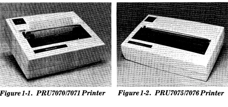
Most of the figures in this manual show the PRU7070/7071. Except for width and weight, the PRU7070/7071 is identical to the PRU7075/7076 in appearance, and any references to parts and their positions are the same.
Honeywell inviteR you to URe the Technic;:) 1 Pl1hlicat.ion~ Rem~rk~ F()rm ~t the end
of this manual to note any publications errors or to offer any suggestions for improvement.
Honeywell disclaims the implied warranties of merchantability and fitness for a partic-ular purpose and makes no express warranties except as may be stated in its written agreement with and for its customer.
Contents
Section 10 Introduction
Section 2. Controls and Indicators
POWERON/OFFSwitch ... 2-1
Operation Panel. . . .. 2-2
Operation Panel Switches ... 2-2
ON LINE/OFF LINE (and PRINT-TEST) ... 2-2
FORM FEED ... 2-3
Operation Panel Indicator Lights. . . ..
2-3ONLINE ... 2-3
POWER ON ... 2-3
Additional Operation Controls . . . .. 2-4
Paper Movement Knob . . . .. 2-4
Sprocket Lock Knobs and Covers ... 2-4
Self-Checking Capability. . . .. 2-4
Section 3. Operation
Power On and Startup Procedure . . . .. 3-1
PRINT-TEST Procedure ... 3-2
ON LINE/OFF LINE Status Procedure ... 3-3
FORM FEED Procedure ... , , .. " 3-3
Power Off Procedure ... . . . .. 3-4
Self-Checking Procedures ... 3-4
Paper Loading and Alignment Procedure. . . .. 3-7
Ribbon Changing Procedure . . . .. 3-8
Section 4. Printer Commands and Programming Information
Rules for Attribute Combinations ... 4-20
Parity Errors ... 4-20
Command Information ... 4-21
Section 5. Functional Description
Appendix A. Configuration Controls
Form Length Selection ... A-3
Appendix B. Maintenance, Shipping, and Installation Procedures
Maintenance ... B-1 Shi pping and Installation ... B-1 Unpacking the Unit ... B-1 Packing the Unit ... B-2 Host-Printer Connection ... B-2 Direct Connection ... B-3 Modem Interface Connection ... B-4 Data Cable Connecting Procedure ... B-4 Cable Connection for the PRU7070/7075 Printers ... B-4 Cable Connection for the PRU7071/7076 Printers ... B-5 Positioning the Jumpers ... B-5 Jumper Positions for the TOP Set of Gold Pins ... B-7 Jumper Positions for the BOTTOM Set of Gold Pins ... B-7
Appendix C. Specifications
Appendix D. ASCII Character Set and Command Sort List
Figures
1-1 PRU7070/7071 Printer ... 1-1 1-2 PRU7075/7076 Printer ... 1-1
2-1 POWERON/OFF Switch Shown in the OFF Position ... 2-1
2-2 Operation Panel ... 2-2 2-3 Pap(lr Movement K nnh . . . 2-5 2-4 Internal Mechanics of the Printer ... 2-5 3-1 Power Cord and Data Cable Receptacle. . . .. 3-1 3-2 Sample PRINT-TEST Output ... 3-3 3-3 Paper Chute ... 3-6 3-4 Internal Mechanics with Loaded Paper. . . .. 3-7 3-5 Ribbon Cartridge. . . .. 3-9 5-1 Actual 10.0 CPI Size and Width ... 5-1 5-2 Actual 16. 7 CPI Size and Width ... 5-2 5-3 Actual Output for Double-Width Characters. . . .. 5-3 B-1 Host-Printer Connection ... B-3 B-2 JumperandPins ... B-5 B-3 Blue Jumpers Covering Two Sets of Gold Pins ... B-6 B-4 Two Sets of Gold Pins ... B-6 B-5 Graphic Representation of3 Gold Pins on the Printer Circuit
Tables
4-1
Codes for Line Graphics Symbols . . . .. 4-5
4-2
Form Length Commands ... . . . .. 4-7
A-1
Internal Switch Settings ... A-2
A-2
Form Length Selection by Internal Switch ... A-3
B-1
Bell System Asynchronous Data Sets ... B-4
C-1
Print Characteristics ... C-2
C-2
Media Specifications ... C-3
D-1
PRU7070/7071
&PRU7075/7076 ASCII Character Set ... D-1
D-2
Command Sort List of ASCII, Hexadecimal, Octal, and
Section
1
Introduction
Figure 1-1. PRU707017071 Printer
Figure 1-2. PRU707517076Printer
Honeywell's PRU7070/7071 and PRU7075/7076 printers are compact, light-weight, quiet, desktop printers that have been designed specifically for use in office environments. The following features have been incorporated to provide convenience, simplified operation, speed, and flexibility. Each printer:
• Has both RS-422-A and RS-232-C interfaces
• Has efficient, bidirectional, logic-seeking print function
• Prints 100 characters-per-second
• Prints the full set of uppercase and lowercase alphabet characters as well as numerics, special symbols, and underscore
• Prints 11 line graphics symbols
• Prints elongated characters (double width) for highlighting
[image:7.612.157.556.234.421.2]• Prints 6 or Slines per inch so most common forms can be accommodated
• Prints an original and up to two copies offorms from 3 to 10 inches wide for the PRU7070/7071 and forms from 3 to 15 inches wide for the PRU7075/7076
• Provides a form feed switch to advance paper
• Accommodates forms from 3.5 to 14 inches long
• Uses cartridge ribbon with Mobius loop to ensure clean ribbon changing
• Checks characters for parity errors before printing and either prints a diamond in place of any character in error or requests data block retransmission
• Initiates a local test to proof operation
• Provides ID and complete device status to host on request
The printers have the reliable design and wide performance range that make them an intelligent choice for any business, and they can fit comfortably wherever Honeywell systems are used in applications.
The printers have many features that come standard including an internal switch-enabled automatic line feed on carriage return, a paper-out detector located approx-imately two inches below the printing line, and a paper tear bar. An easily access-ible operator panel mounted on the printer cover allows the operator to control online/offline status, form feed, and the execution of an internal
Section
2
Controls and Indicators
This section describes the functions of the controls and indicators of the printers.
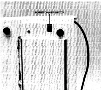
POWER ON/OFF Switch
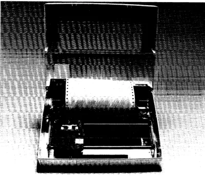
[image:9.617.157.498.372.673.2]This switch, which is used to turn the power on or off and initialize the printer, is located under the printer in the right rear corner. See Figure 2-1, which shows the bottom of the printer.
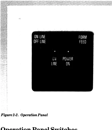
Operation Panel
[image:10.612.111.478.134.559.2]The Operation Panel (Figure 2-2) is located on the top of the cover in the left rear corner of the printer. The panel consists of two switches (ON LINE/OFF LINE and FORM FEED) and two indicator lights (ONLINE and POWER ON).
Figure
2-2.
Operation Panel
Operation Panel Switches
ON LINE/OFF LINE (and PRINT-TEST)
When the printer is online, the ONLINE indicator will be lit, and the printer is able to receive data from the directly connected controller or adaptor.
When the printer is offline, the ONLINE indicator will not be lit, no data can be received from the controller or adaptor, paper can be loaded, and a local form feed can be performed.
The Print-Test procedure explained in Section 3 must be initiated immediately after powering on by pressing the ON LINE switch.
FORM FEED
This switch allows you to perform a FORM FEED procedure when the ON LINE indicator is not lit. The FORM FEED procedure advances the paper to the begin-ning of the next form if the paper has been properly aligned using the Paper Move-ment Knob, Figure 2-3. This procedure has no effect if the ONLINE indicator is lit.
Operation Panel Indicator Lights
ONLINE
When this indicator is lit, the printer is available to receive print data imme-diately from the controller.
Note: The FORM FEED and PRINT-TEST procedures cannot be performed when this indicator is lit.
When this indicator blinks, either a fault has occurred or the printer is out of paper. See the SELF -CHECKING procedure in Section 3 to handle this problem.
When the ON LINE indicator is not lit, the printer cannot receive messages from the controller.
POWER ON
Additional Operation Controls
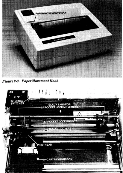
Paper Movem.ent Knob
This knob is a black, wheel-shaped knob that protrudes through the top cover and is located to the left of the platen. The paper movement knob allows you to move the paper up or down and position the paper wherever desired. See Figure 2-3.
These knobs and covers allow you to position the paper from side to side, adjust the sprockets to the width of the paper, and correct any strain on the paper. See Figure 2-4. The PAPER LOADING AND ALIGNMENT procedure in Section 3 explains how to use the sprocket lock knobs and covers.
Self-Checking Capability
The printers feature the capability to check printing performance for faults that may occur during operation. Before being printed, data received from the con-troller is checked for parity errors. If any character has incorrect parity, the printers, under switch control, will print a diamond in place of any characters that are received in error or request that the data block be retransmitted by the host system.
When the POWER ON/OFF switch is turned on, the printers will perform an ini-tialization routine, a fault check, and a paper-out check to verify that they are operable. When this check has been successfully completed, the ON LINE
indicator will be lit, the host system will be notified, and normal usage can begin. If a printer fault or paper out is detected, the ON LINE indicator will blink to
indicate that the printers cannot be used, and the host system will be notified. See Section 3 for an explanation of the SELF -CHECKING procedure.
Figure
2-3.PaperMovementKnob
Section
3
Operation
This section describes the procedures necessary to operate the printers. Honeywell recommends that anyone using the printers first read through all of the steps
before performing any procedure.
Power On and Startup Procedure
1. Check to see that the power cord is plugged into the ac wall outlet. See Figure 3-1.
2. Check to see that the data cable is connected properly to the printer. Figure 3-1 shows the receptacle for the data cable. If the data cable is not connected to the . printer, follow the connecting procedures in Appendix B.
[image:14.615.152.561.409.654.2]I I I I I I I I I I I I I II I
I
I
Figure3-l. PowerCordandDataCableReceptacle
3. Ifpaper needs to be loaded into the printer at this time, see the ~~Paper Loading and Alignment Procedure" later in this section.
4. Locate the POWER ON/OFF switch on the bottom right rear of the printer. See Figure 2-1.
5. Turn the printer on by pulling the POWER ON/OFF switch toward the front of the printer to the ON position.
6. Check to see if the POWER ON indicator is lit on the Operation Panel (see Figure 2-2). The ON LINE indicator will also light after a short delay. If the POWER ON indicator is not lit, check first to ensure that the power outlet is active. This can be done by plugging in a lamp and seeing ifit lights. If the power outlet is working, turn off the printer and call your Customer Services Representative.
Note: If the printer is not used for a few days (e.g., after a weekend), the exposed section of ribbon will become dry. Before you use the printer again, you should advance the ribbon by turning the red ribbon advance knob clockwise (see Figure 3-5) until a new section of ribbon is positioned in front of the printhead.
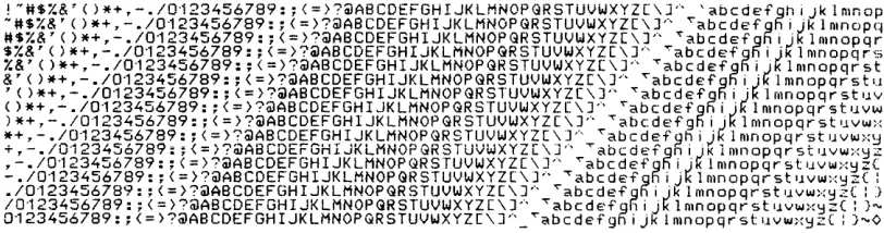
Print-Test Procedure
1. Turn on the printer by pulling the POWER ON/OFF switch (Figure 2-1) toward the front of the printer.
2. Immediately after you
turn
on the printer, press the ON LINE/OFF LINE switch located on the Operation Panel.Note: Do not hold down the ON LINE/OFF LINE switch. Just quickly press it to begin the Print-Test procedure. A delay of more than two seconds
between powering on and pressing the O:N LIl~E sw itch will abort the Print-Test. Powering the printer off then on again will be necessary to retry the Print-Test. Check the Operation Panel to see if the ON LINE indicator is lit. It should not be lit during the Print-Test procedure. The Print-Test procedure will not be performed if the ON LINE/OFF LINE switch is pressed either too quickly or too long after the power is turned on. If you are unsuccessful starting the Print-Test, try it again until you get the cor-rect timing.
!-"SZ&"()*+,-./0123456789:;{~>?@A8CDEFGHIJKLMNOPGRSTUVWXYZ \JA 'abcdefgniJklmnop -"SZ&'()*+,-./0123456789:;<=)?@ABCDEFGHIJKLMNOPGRSTUVWXYZ[ ]A ~abcdEfg~ijklrnnopq
"SZ&"()*+,-./0123456789:;<=}?@ABCDEFGHIJKLMNOPGRSTUVWXYZ[\ A ~abcdefghljklmnopqr
$Z&'()*+,-./0123456789:;<=)?@ABCDEFGHIJKLMNOPGRSTUVWXYZ[\] Ta bcdefgfiijklmnopqrs
Z&'()*+,-./0123456789:;<=)?@ABCDEFGHIJKLMNOPGRSTUVWXYZ[\]A TabcdefgfiiJklmnopqrst &'()*+,-./0123456789:;(=}?@ABCDEFGHIJKLMNOPGRSTUVWXYZ[\]A ~abcdefgRijklmnopqrstu
, ( ) *+. -. /0·123456789: ; < = }?@ABCDEFGHIJKLMNOPGRSTUVWXYZ[\J" ""<"abcdefgn i jk 1 mnopqr st '.J.V
()*+,-./0123456789:;<=)?@ABCDEFGHIJKLMNOPGRSTUVWXYZ[\]A ~abcdefgRijklmnopqrstuvw
)*+.-./0123456789:;<=)?@ABCDEFGHIJKLMNOPGRSTUVWXYZ[\]A ""<"abcdefghiJklmnopqrstuvwx *+,-./0123456789:;(=)?@ABCDEFGHIJKLMNOPGRSTUVWXYZ[\]A ~abcdefghi)klmnopqrstuvwx~
+,-./0123456789:;<=>?@ABCDEFGHIJKlMNOPGRSTUVWXYZ[\]A TabcdEfgRiJKlmnopqrstuvwx~Z
,-./0123456789:;(=)?@ABCDEFGHIJKLMNOPGRSTUVWXYZ[\]'· ~abcdefghijklmnopqrstuv~x~Z(
-./0123456789:;{=)?@ABCDEFGHIJKLMNOPGRSTUVWXYZ[\]A TabcdefgRijklmnopqrstuvwx~Z(:
./0123456789:;C=}?@ABCDEFGHIJKLMNOPGRSTUVWXYZ[\]A ~abcd€fgfiijklmnopqrstuvwx~Z(:)
/0123456789:;(=)?@ABCDEFGHIJKLMNOPGRSTUVWXYZ[\]A TabcdefgRijklmnopqrstuvwx~Z(:}~
[image:16.612.156.562.54.161.2]0123456789:;<=)?@ABCDEFGHIJKLMNOPQRSTUVWXYZ[\]A_~abcdefgRijklmnopqrstuvwx~Z{: )~O
Figure
3-2.
Sample Print-Test Output
4. When the 16th line is being printed, press and hold the ON LINE/OFF LINE switch. This will stop the Print-Test when the printhead reaches either end of the line.
5. Press the ON LINE/OFF LINE switch. The printer will enter the online state and the ON LINE indicator should light. When the ON LINE indicator lights, the printer is ready for use.
Online/Offline Status Procedure
1. To change the online/offiine status of the printer, press the ON LINE/OFF LINE switch located on the Operation Panel.
2. When the switch is pressed while the printer is online, the printer will go offiine and the host system will be notified.
3. When the switch is pressed while the printer is offiine, the printer will go online and the host system will be notified.
4. Check the Operation Panel to see if the ON LINE indicator is lit. If the ON LINE indicator is not lit, the printer is offline. If the ONLINE indicator is lit, the printer is online. The printer must be online to receive data from the controller. The printer must be offiine to load paper, perform a local FORM FEED, or perform a Print-Test.
FORM FEED Procedure
1. Check to see that the paper has been loaded and aligned properly and that the ONLINE indicator is not blinking. If the ON LINE indicator is blinking, check to see if paper is feeding into the printer.
3. Locate the FORM FEED switch on the Operation Panel.
4. Press the FORM FEED switch on the Operation Panel to perform the FORM FEED procedure. The paper should advance to the top of the next form, if the paper has been loaded and aligned properly. If the form does not advance as expected, check the form length switch settings. See Table A-2.
Power
Off Procedure
1. Locate the POWER ON/OFF switch on the bottom right of the printer (Figure 2-1).
2. Press the switch away from you to the OFF position.
3. Check the two indicator lights on the Operation Panel. Neither of them should be lit.
Self-Checking Procedures
The following situations may occur when you are operating the printer. If your printer is not operating properly, you should check the internal switch settings that are described in Appendix A to see ifall12 switches are set properly. You should also check the positions of the two bluejumpers on the two sets of gold pins that are described in Appendix C. Correct switch andjumper positions are required for normal printer operation.
1. A diamond is printed in place of a normal character.
This probably means: The printer has received an incorrect character. You should:
a. Check to see that the data cable is connected securely to the printer. See Figure 3-1.
b. Check to see that the power cord is plugged into the wall socket securely. c. If the data cable and power cord are both secure, you may have a more
serious problem and should call your Customer Services Representative.
2. A series of diamonds is printed in place of characters. This probably means: A switch is set wrong.
You should:
a. Read Appendix A for correct switch settings.
3. The ONLINE indicator is blinking.
This probably means: You are out of paper or you have a fault condition. You should:
a. Determine that the paper supply is adequate and that the paper is not torn, which can expose the Paper Out switch (located 2 inches below the print line).
b. Ifpaper out is not the problem, place the printer in the offiine state and then return the printer to the online state.
c. If the indicator continues to blink, turn off the power to the printer and call your Customer Services Representative.
4. One line is printing over another because the paper is not advancing.
This probably means: The punched holes on the sides of the paper have been
torn or you have a printer failure.
You should:
a. Lift up the sprocket lock covers (Figure 2-4) and check to see if the punched holes on the sides of the paper are tom.
b. If these holes are tom, lift both the left and right sprocket covers and remove the piece of paper with the torn holes.
c. Move the remaining paper manually so that new holes can be positioned over the sprocket teeth.
d. Close the sprocket covers and use the Paper Movement Knob to advance the paper to the next top-of-form.
e. If the paper holes are not torn, you may have a more serious problem and
C! 'hn" lrl r>a 11 un,,-r t:llC!tnTYIO-r ~-ru;r>OQ Ron-roQont!:at;uo
0.1..1.'-' ... ..L""'-"'CA. ... .&. J" ... .L ' - ' ... u""''-'.L ... '-'.&. "'-''-'.L ,. .L"""'''''' .£."""'l"'.L ""'u""" ... ""''-4U.L ... """_
5. One line is overlapping or printing over another.
This probably means: The bluejumper on the BOTTOM set of gold pins is
covering the wrong gold pins.
You should:
a. Reposition the blue jumper according to the requirements given in AppendixB.
b. If the printer continues to operate improperly, call your Customer Services Representative.
6. Too much space is occurring between printed lines.
This probably means: The blue jumper on the BOTTOM set of gold pins is
covering the wrong gold pins.
You should:
I
b. If the printer continues to operate improperly, call your Customer Services Representative.
7. The printer is not communicating at all.
This probably means: The bluejumper on the TOP set of gold pins is covering the wrong gold pins.
You should:
a. Reposition the bluejumper according to the requirements given in AppendixB.
b. If the printer continues to operate improperly, call your Customer Services Representative.
8. Paper is not advancing.
This probably means: There is an internal paper jam, or you have a printer failure.
You should:
a. Check the paper chute (Figure 3-3) on the back of the printer to see if paper coming out of the top of the printer is resting on the top of the paper enter-ing the paper chute.
b. Ifpaper from the top of the printer is also entering the paper chute, remove it by pulling out all paper in the chute.
c. Open the printer cover and remove any excess paper causing the paper jam. d. Reload new paper.
e. If an internal paper jam is not the problem, you may have a more serious problem and should call your Customer Services Representative.
o.
111111111111111111
Paper Loading and Alignment
Procedure
The printers have this easy procedure for loading paper:
1. Position the stack of paper behind the printer.
2. Ifusing single copy paper, take the top sheet of paper and fold it onto the attached second sheet. This makes the loading procedure easier.
3. Open the printer by pulling the cover up and away from you.
4. With both hands, feed the folded paper into the paper chute (Figure 3-3) located under the printer. Keep feeding the paper into the chute until you see the top of the paper appear just above the protective plastic shield under the platen. See Figures 2-4 and 3-4.
[image:20.617.156.557.338.681.2]5. Turn on the printer to allow the printhead to position itself to the left of the platen. This will happen automatically. Figure 3-4 shows the proper loading position for the printhead.
Note: If the paper is narrower or wider than the paper that was pre-viously in the printer, the sprocket locks must be adjusted. See Figure 2-4. You can adjust the sprocket locks by pulling the black tab toward you and moving the sprocket lock to the desired position to hold the paper. Push the black tab back to secure the sprocket lock. The left sprocket must be positioned first and must be to the left of the leftmost printhead position.
6. Check to see that the left sprocket is positioned to the left of the leftmost print-head position. Pull out the left sprocket lock cover (Figure 2-4) and position the left margin of the paper by aligning the holes in the paper with the sprockets on the wheel under the sprocket lock cover. Gently snap the sprocket lock cover back into position.
7. Pull out the right sprocket lock cover (Figure 2-4) and position the right margin of the paper. Ifnecessary, adjust the right sprocket lock. See the pro-cedure in the Note under Step 5. Gently snap the sprocket lock cover back into position.
8. Close the printer cover while guiding the top of the paper through the opening in the printer cover. See Figure 3-4.
9. Adjust the top of the form by moving the black Paper Movement Knob back and forth. See Figure 2-3. The top of the form is the first line where you expect printing to appear. The printhead should be at that line. You may now perform the ONLINE, PRINT -TEST, or FO RM FEED procedure. The ONLINE pro-cedure must be performed before the printer can receive information from the controller.
Note: When printing starts, you must ensure that the first few forms coming out of the printer are stacked properly in back of the printer. This attention is necessary to avoid paper dropping over the back of the printer and resting on top of the paper entering the paper chute (Figure 3-3), which couid cause an Internal paper Jam.
Ribbon Changing Procedure
The printers provide a clean, compact ribbon cartridge package that snaps in and out of place easily and quickly. To change the ribbon cartridge, follow this pro-cedure:
1.
Open the printer by lifting the cover up and away from you.3. Remove the new cartridge from its cellophane packaging.
4. Pull out, remove, and dispose of the spring clamp located on the right side of the new cartridge. See Figure 3-5.
5. Turn the red knob on the top of the cartridge clockwise to tighten the ribbon tension.
6. Fit the ribbon over the front of the printhead and insert the cartridge into the same place where the old cartridge was. It should easily snap into place. Adjust the ribbon tension, ifnecessary, by turning the red tension knob on the top of the cartridge clockwise.
RIBBON
[image:22.613.157.423.215.544.2]SPRING CLIP
Section
4
Printer Commands
and
Programming Information
I
CPS
CPS
Command Name: SET16.7CPIPITCH
ASCII Code: ESCs8
Hexadecimal: 1B-73-38
Octal: 033-163-070
Function:
This command overrides the internal switch setting and sets character spacing to 16.7 cpi. Initially the character spacing is determined by internal switch setting (see Appendix A). Print character spacing can be changed by software at any time except in the middle of a line by sending the printer the appropriate command immediately following the CRiLF from a previous line. Pitch is not changed by the Restore attribute. At RESET TO INITIAL STATE (RIS), pitch returns to the internal switch setting.
If characters of a different pitch are to be printed on the same line, the software should send a CR (No LF) followed by the new pitch assignment and characters that are properly spaced to account for previously printed characters effectively printing twice on the same line. Unlike the double-width attribute, the spacing is not based on a simple character count, so great care should be taken when using multiple pitches per line. When printing the first pass at initial pitch, printing an 80th or 132nd character will initiate an automatic line feed causing the second pass to print on the next line.
At 16.7 cpi, 132 characters can be printed in the 8 inch space normally occupied by 80 characters at 10 cpi. The PRU7075r7076 allows printingof220 characters in the 13.2 inch space normally occupied by 132 characters at 10 cpi.
CPT
CPT
Command Name: SETI0CPIPITCH
ASCII Code: ESCs5
Hexadecimal: IB-73-35
Octal: 033-163-065
Function:
This command overrides the internal switch setting and sets the character spacing to 10 cpi. Initially the character spacing is determined by internal switch setting (see Appendix A). Print character spacing can be changed by software at any time except in the middle of a line by sending the printer the appropriate command imme-diately following the CR/LF from a previous line. Pitch is not changed by the Restore attribute. At RESET TO INITIAL STATE (RIS), pitch returns to the internal switch setting.
If characters of a different pitch are to be printed on the same line, the software should send a CR (no LF) followed by the new pitch assignment and characters that are properly spaced to account for previously printed characters, effectively printing twice on the same line. Unlike the double-width attribute, the spacing is not based on a simple character count, so great care should be taken when using multiple pitches per line. When printing the first pass at initial pitch, printing an 80th or 132nd character will initiate an automatic line feed causing the second pass to print on the next line.
LGS
LGS
Command Name: SETLINEGRAPHICS
ASCII Code: ESCG
Hexadecimal: IB47
Octal: 033107
Function:
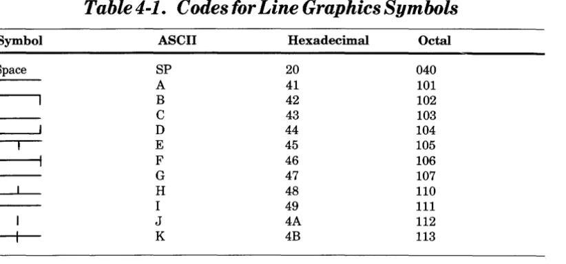
The LGS command sets the printer to Line Graphics mode when it follows a car-riage return, CR or CR, LF. When the printer is in this mode, only graphics char-acters can be generated for printing. Eleven graphics symbols can be generated by selected codes. These codes are taken from the ASCII set shown in Appendix D and are shown in Table 4-1. In addition, CR, LF and LGR are effective. Other com-mands, including attributes DWC and CUS, are ignored.
Line graphics can be printed at either 10 cpi or 16.66 cpi, but line density must be 61pi. Line graphic codes following LGS are separated into print lines by CR,LF at the end of each line. Each line is printed in two passes at half-line feed. After the second pass, the end-of-line feed command causes a second half-line feed. It is important that the final LF command be given before leaving the graphics mode, otherwise a full line feed will occur.
It is possible to insert text into a line graphic pattern by resetting the graphic mode at the completion of a line. The inserted text must be spaced to accommodate the graphic pattern. After the text is printed, a CR followed by LGS allows over-printing the text line with line graphics. For boxing text, the text is inserted after the top of the box is programmed and the bottom is then overprinted.
Line graphics always require a print command (CR). After a timeout with data stored, automatic printout occurs for normal data but not for line graphics.
Inserted text can be in either condensed or double-width mode. If characters of a dif-ferent pitch are to be inserted on the same line, the software will send a CR (no LF) followed by the new pitch assignment and characters that are properly spaced to account for previously printed characters effectively inserting two text strings on the same line. Unlike the double-width attribute, the spacing is not based on a simple character count, so great care should be taken when using multiple pitches per line. When printing the first pass at initial pitch, printing an 80th or 132nd character will initiate an automatic line feed causing the second pass to print on the next line.
LGS
Symbol
Space
(
LGS
Table
4-1.
Codes for Line Graphics Symbols
ASCII Hexadecimal Octal
SP 20 040
A 41 101
B 42 102
C 43 103
D 44 104
E 45 105
F 46 106
G 47 107
H 48 110
I 49 111
J 4A 112
[image:27.615.165.576.99.291.2]LGR
LGR
Command Name: RESET LINE GRAPHICS
ASCII Code: ESCF
Hexadecimal: 1B46
Octal: 033106
Function:
The LGR command takes the printer out of Line Graphics mode; otherwise, LGR is ignored.
FLS
FLS
Command Name: SETFORMLENGTH
ASCII Code: ESC ~~SP ACE" ~~XY"
Hexadecimal: 1B-20-~~XY"
Octal: 033-040-((XY"
Function:
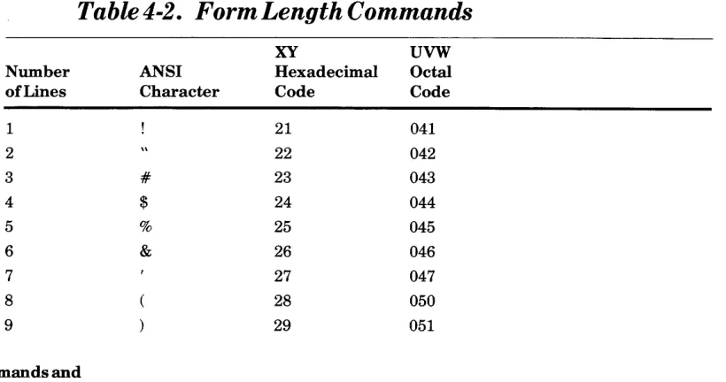
This command overrides the internal switch settings and sets specific form lengths that are defined as a number of lines. Common lengths defined in inches can be selected by an operator setting the easily accessible switches (see Table A-2 in Appendix A). These lengths or other varying lengths can be down-loaded via the FLS command, but they must be expressed in the number of lines per form. Line density and length in number of lines must be considered when setting the form length. When the form length is down-loaded, the current physical print line posi-tion becomes the first logical line of the form. Down-loaded form length is saved while the printer is offiine. Reset or power up returns form length to the selected switch value.
XY values are hexadecimal digits represented by an ASCII code in the range of21 through 7E (see Table D-1 in Appendix D). The value 21 corresponds to a form length of one line; the value 7E corresponds to a form length of94 lines; values 20 and 7F are ignored.
Table 4-2 gives the Form Length Commands, listing the number of lines, the ANSI character, the hexadecimal code, and the octal code.
Table
4-2.
FormLengthCommands
[image:29.612.150.560.505.721.2]FLS
FLS
Table
4-2
(Cont).
FormLengthCommands
XY UVW
Number ANSI Hexadecimal Octal of Lines Character Code Code
10
*
2A 05211 + 2B 053
12 2C 054
13 2D 055
14 2E 056
15 n"D nf!:'7
'::'1.' VVI
16 0 30 060
17 1 31 061
18 2 32 062
19 3 33 063
20 4 34 064
21 5 35 065
22 6 36 066
23 7 37 067
24 8 38 070
25 9 39 071
26 3A 072
27 3B 073
28 < 3C 074
29 3D 075
30 > 3E 076
31 ? 3F 077
32 @ 40 100
33 A 41 101
34 B 42 102
35 C 43 103
36 D 44 104
37 E 45 105
38 F 46 106
39 G 47 107
40 H 48 110
41 I 49 111
42 J 4A 112
43 K 4B 113
44 L 4C 114
45 M 4D 115
46 N 4E 116
47 0 4F 117
48 P 50 120
[image:30.617.117.525.88.712.2]FLS
FLS
Table
4-2
(Cont). Form Length Commands
XY UVW
Number ft_NSI Hexadecimal Octal of Lines Character Code Code
49 Q 51 121
50 R 52 122
51 S 53 123
52 T 54 124
53 U 55 125
54 V 56 126
55 W 57 127
56 X 58 130
57 Y 59 131
58 Z 5A 132
59 5B 133
60 5C 134
61 5D 135
62 1\ 5E 136
63 5F 137
64 60 140
65 a 61 141
66 b 62 142
67 c 63 143
68 d 64 144
69 e 65 145
70 f 66 146
71 g 67 147
72 h 68 150
73 69 151
74 j 6A 152
75 k 6B 153
76
6e
15477 m 6D 155
78 n 6E 156
79 0 6F 157
80 p 70 160
81 q 71 161
82 r 72 162
83 s 73 163
84 t 74 164
85 u 75 165
86 v 76 166
[image:31.612.153.564.99.713.2]FLS
Table
4-2
(Cont). Form Length Commands
Number
of Lines
88 89 90 91
I
9293
I
94Printer Commands and
ANSI Character
x
y
z {
I
}
XY UVW
Hexadecimal Octal Code
78 170
79 171
7A 172
7B 173
7C 174
7D 175
7E 176
[image:32.613.112.513.89.237.2]LDS
LDS
Command Name: SET6LPI
ASCII Code: ESCU
Hexadecimal: 1B-55
Octal: 033-125
Function:
LDE
LDE
Command Name: SET8LPI
ASCII Code: ESCu
Hexadecimal: 1B-75
Octal: 033-165
Function:
This command overrides the internal switch setting and sets the line density at 8 lines-per-inch. The set value of6lines-per-inch can be overridden by LDE and changed to the alternate value. The down-loaded line density value is saved when the printer is offiine. Line density changes should be made at the beginning of a message. The new form length must also be entered at the same time by FLS, otherwise page synchronization is lost on the next Form Feed command.
DWC
DWC
Command Name: SET DOUBLE WIDTH
ASCII Code: ESCs2
Hexadecimal: IB-73-32
Octal: 033-163-062
Function:
This command allows the printing of elongated characters, doubling the width of the current horizontal character and the inter-character space. Using this
CUS
CUS
Command Name: SETUNDERLINE
ASCII Code: ESCs_
Hexadecimal: 1B-73-5F
Octal: 033-163-137
Function:
This command allows a continuous underline on any character string. This func-tion is performed during the same printing pass of the printhead using the ninth lower needle. Underlining is automatically discontinued by firmware on a true descender character as required by the font characteristics. The underline bute is not automatically reset at the end of the received line. The Restore attri-bute or a new attriattri-bute must be received in order to close the underlined field. Underlined printing can be combined with any of the previously mentioned attri-butesofCPT, CPS, and DWC.
RSR
RSR
Command N arne:
RESTORE
ASCII Code:
ESCsR
ESCsr
Hexadecimal: 1B-73-52 1B-73-72
Octal: 033-163-122 033-163-162
Function:
This command is used to reset all attributes except Pitch. Attributes are CPT,
I
RIS
RIS
Command Name: RESET TO INITIAL STATE
ASCII Code: ESCc
Hexadecimal: 1B-63
Octal: 033-143
Function:
This command is used by the driver as part of its function and is not expected to be issued by the application. The application can cause the driver to issue an RIS com-mand to the printer under the rules for the operating system.
This command causes an immediate printer busy condition followed by an ini-tialization routine, resets form length to the default setting, defines top-of-form, clears the buffer, positions the printhead to the leftmost position, and signals the Host system when complete.
FF
FF
Command N arne: FORM FEED
ASCII Code: FF
Hexadecimal:
OC
Octal:
014
Function:
This command causes the printer to start printing the buffer content, if any, and to execute a form feed, moving the paper to the head of the next form even if the paper will run out during paper movement. When used in conjunction with the FLS command, the FF command provides a smooth, continuous movement for form advancement. A continuous movement is not produced from a sequence ofLF commands.
I
LF
Command N arne: LINE FEED
ASCII Code: LF
Hexadecimal:
OA
Octal: 012
Function:
This command causes the execution of a line feed operation wherever encoun-tered in the print line. A printer busy condition occurs while the line feed is executed. A sequence of line feed commands will cause a printer busy for each LF when executed.
LF
CR
Command Name: CARRIAGERETURN
ASCII Code: CR
Hexadecimal: OD
Octal:
015
Function:
This command causes the printer to start printing the buffer content, if any, and perform a line feed if the internal switch is set for line feed on carriage return (new line).
CR
Rules for Attribute Combinations
Attributes can be combined according to these rules:
• Attributes are effective at the point where they appear in the data stream.
• Sequences of allowed attributes are closed by a subsequent printable character.
• Attributes are in force until receiving a new attribute or the Restore attribute.
• The Pitch attribute changes only by the assignment of a new pitch. Pitch
Parity Errors
When a parity error occurs and the request data block retransmission switch is not set, escape sequences are handled as follows:
• Escape code with a parity error - a diamond is printed for the Escape code received in error and the following codes of the sequences are printed.
• Sequences with a parity error - a diamond is printed in place of the character received in error and the preceding part of the sequence is dis-carded while the following sequence code is printed.
• If the request data block retransmission switch is set, no printing takes place until the block has been correctly received.
Command Information
The followip.g commands common to these Honeywell printers: PRUI005/7005 and PRUI003/7003 will be ignored by the PRU7070/7071 and the
PRU7075/7076 printers:
ESC H ESC J ESC 3 ESC 4 ESC 1
ESC 2 BEL BS HT VT
Online Standby Set vertical tab Clear all vertical tabs Tab set horizontal Clear horizontal tabs Bell
Backspace Horizontal tab Vertical tab
Section
5
Functional Description
This section describes some of the functional characteristics of the PRU7070/7071 and the PRU7075/7076 printers employing a 9-needle printhead and providing 100 characters-per-second print speed at 10 or 16.7 characters-per-inch on a 9 x 7 dot matrix (vertical x horizontal).
Printing Approach
The carriage moves continuously during printing, which is started after recep-tion of a data block. Printing is performed with the logic-seeking approach, which means that before a line is printed, the printer examines the actual position of the carriage and finds the left and right limits of the printable characters. Then the printer makes a decision whether to print forward or backward starting from left or right. In this way, the carriage movement without printing is minimized, and the actual throughput can reach higher values according to the actual print pat-terns. Printing is performed while the carriage is moving with a constant speed over the line length. Data reception is overlapped with the printing.
Normal Printing (10 CPI)
Character spacing is determined by internal switch setting (see Appendix A).
Normal print character spacing can be changed by software by sending the printer the appropriate command at the beginning of a printable data line.
10 Characters Per inch
abcdefghijklmnopqrstuvwxyzABCDEFGHIJKLMNOPGRSTUVWXYZ
1234567890'NM$X&'()=_~A: I\@(()]+;*=(,).?I_
Figure 5-1. ActualIO.OCPISizeandWidth
Compressed Printing (16.7 CPI)
When the printers are powered up, character spacing is determined by internal switch setting (see Appendix A). Compressed printing can be selected by a ~~Set 16.7 CPI" command and disabled only by a ~~Set 10 CPI" command. Character density commands must be sent at the beginning of the line; character density cannot be changed when a line is printing.
Compressed characters are printed with an actual character pitch of16. 7 cpi, and their horizontal width and inter-character space is proportionally reduced.
When compressed printing is activated, the same print speed of that at 10 cpi is maintained and the other running attributes are not restored. In the
PRU7075/7076, compressed line length printing is 220 characters that are left justified.
16.7
Character per inch
ibcdefghijkllDopqrstuvlxyzABCDEFGHIJKlMNOPtRSTUVWXYZ
1234567890!·IS%&'()=-~h:I'a{[}]+;*:(,).?I_
Figure
5-2.Actual
16. 7CPI Size and Width
Elongated Printing (Double-Width)
Elongated characters are printed, doubling the current horizontal character width Hnd the inter-character space. Using this printingcapability~ it is possible to print lines up to 40 elongated normal characters or up to 66 elongated compressed characters (8.33 characters per inch) on the PRU7070/7071 and 66 or 110 charac-ters on the PRU7075/7076.
Elongated printing is software selectable by means of the Set Double-Width Printing attribute. Elongated printing terminates when any new attribute or the Restore attribute is assigned.
When an elongated character is going to be printed in the last printable column, the character is printed without the elongation attribute. The print speed is halved
~o
C P I d o u b 1 e w i d t h
abcde~ghiJk1mn~pqrstuvwxyz
ABCDEFGHIJKLMNOPQRSTUVWXYZ
1234567a90~-M$X&F()=-~~: :
'~CC3~+~*=<F>-?/_
16.7
DOUBLE WIDTH
abcde~Ghijkl.nopqr.tuywxyz
ABCDEFGHIJKLHNOPQRSTUVWXYZ
[image:46.613.150.562.55.304.2]1234S67B90!-M.%&F()=_~~::'~([)J+;*I(.>.?/_
Figure
5-3.
Actual Output for Double-Width Characters
Line Graphics Printing
Line Graphics printing provides the capability to generate contiguous horizontal and vertical lines. It can be used to outline forms, organize areas within a form, and construct simple charts.
ITnderline Printing
This feature allows a continuous underline on any character in the same line. This function is performed during the same printing pass of the printhead using the ninth lower needle.
Underlining is automatically discontinued by firmware on true descender char-acters as required by the font characteristics.
The underline attribute is not automatically reset at the end of the received line. The Restore attribute or a new attribute must be received in order to close the underlined field.
Autoprint
When the full line length (80 printable characters at 10 cpi or 132 characters at 16.7 cpi for the PRU7070/7071 or at 132 or 220 characters at 10 cpi or 16.7 cpi for the PRU7075/7076) is received without a carriage return/line feed command, the printer immediately prints the line of data followed by an automatic line feed and a column counter positioning to the first column.
After an autoprint execution, the first line feed received will be ignored ifnot preceded by printable characters that are string-closed by a print command. This eliminates the need for a LF when a full line is not ended by a CR plus LF or FF. Attributes are not reset by autoprint.
Line Densities
The default value can be selected by means of an internal switch between 6 or 81pi. These values can be overridden by software.
Down-loaded line density is saved when the printers are offline. The commands cannot be embedded between printable data of the same line.
Line density changes must be made at the beginning of a message. The new form length must be entered by software, otherwise page synchronization is lost on the next form feed command.
Data Buffering
The two printer data buffers each provide room for 127 ASCII codes that can be commands or printable characters. When the printer is placed offline, the buffer content is saved and then printed after the online state is reentered.
Form Length Selection
When the form length is down-loaded, the current physical line position becomes the first logical line of the form. Down-loaded form length is saved while the printers are offline.
External Interfaces
The printers come with a 25-pin receptacle connector in accordance with ISO-IS 211 C physical dimensions. This connector allows a data signal exchange with the host via a suitable cable. Data transfer occurs in asynchronous transmission mode (start/stop) of serial-by-bit characters.
Appendix A
Configuration Controls
The printers are equipped with 12 internal switches (see Figure 2-4) located on the top left section of the printer circuit board. These switches alter various charac-teristics of the printer; however, Honeywell software is designed to control most of these functions for you, and it can override the switch settings. Table A-I explains the function of each internal switch in both the ON and OFF positions.
Typically, the most common settings for the internal switches will be:
Switch Position
1 OFF
2 ON
3 OFF
4 OFF
5 OFF
6 ON
7 OFF
8 ONI
9 OFF
10 OFF
11 OFF
12 OFF
The functions for these switch settings are explained in Tables A-I and A-2.
Table A-I explains the function of each internal switch in both the ON and OFF positions.
Table A-I. InternalSwitchSettings
Switch ON I OFF
I
Function1 X Selects 8 lines per inch
X Selects 6 lines per inch
2 X Selects parity error report
X Selects printing of diamond on parity error
3 X Selects 16.7 characters per inch spacing
X Selects 10.0 characters per inch spacing
4 X Selects the carriage return function and automatically inserts a line feed function after the carriage return
X Selects the carriage return function only
5,6,7 X X Select form lengths. See Table A-2
8 X Selects 9600 baud if switch 9 is in the local (OFF) position (direct connect mode), or selects 300 baud if switch 9 is in the remote (ON) position (modem connect mode)
X Selects 1200 baud
9 X Selects modem connect (remote)
X Selects direct connect (local)
10,11,12 X Select character sets. These switches must always be OFF for the International Character Set.
Form Length Selection
Form length can be selected in two ways:
• Internal switches that are accessible by you
• Software by the program in the host controller
Table A-2 explains the form length values that can be manually selected by internal switch before the printer is powered on. Software can override the switch settings.
TableA-2.
Form Length Selection
by
Internal Switch
FLin FL in Number of Lines Internal Switch Setting Inches 6LPI 8LPI 5 6 7
3.5 21 28 ON ON ON
4 24 32 OFF ON ON
5.5 33 44 ON OFF ON
7 42 56 OFF OFF ON
8.5 51 68 ON ON OFF
11 66 88 OFF ON OFF
12 72 96 ON OFF OFF
14 84 112 OFF OFF OFF
AppendixB
Maintenance, Shipping, and
I nstallation Procedures
Maintenance
No preventive maintenance on a scheduled basis is required.
Shipping and Installation
Packing and unpacking the printer involves simple procedures explained below. If you feel that a more detailed explanation of the set up procedure is needed, you can reference the Setup Procedure for Printers PR U706X & PR U707X manual, Order No.CY03.
Unpacking ihe Unii
1. Remove the printer from its protective package. SA VE the package in case you need to move the printer at a later date and store the protective material that comes with the printer in this package.
2. Remove the strip of tape located around the middle sides of the printer. Removing this tape will allow you to lift the printer cover.
3. Lift the printer cover up and away from you. The internal mechanics of the printer will be covered with protective material.
4. Remove this protective material from the internal mechanics and SA VE it in the protective package for future use.
5. Remove the cartridge ribbon from its plastic bag.
6. Follow the steps in Section 3 for the Ribbon Changing procedure to load the ribbon.
I
8. Place the printer where you desire to use it.
9. Remove the data cable from the pouch in which it was shipped. SA VE the pouch for future use.
10. Connect the data cable to the printer. This procedure is explained later in this section. Figure 3-1 shows the receptacle for the data cable.
WARNING
You must follow the Data Cable Connecting procedure carefully to ensure that a correct connection is made. An incorrect connection could damage the equipment.
11. PI ug in the Power Cord. See Figure 3-1. The printer is now ready for use.
Packing the Unit
1. Disconnect the Data Cable and the Power Cord.
2. Open the printer cover and remove the ribbon cartridge.
3. Pack the ribbon cartridge in a clean envelope or some other protective device.
4. Take the protective material that you have saved and pack this material care-fully around the internal mechanics.
Note: Ensure that the printhead is tied down and not capable of any move-ment.
5. Close and secure the cover to the base of the printer by using either a piece of masking tape or a strong elastic.
6. Carefully place the printer into the box in which it was shipped.
7. Put the data cable into the pouch in which it came.
8. Put the data cable and pouch into the printer box.
9. Seal the box with tape. The printer is ready for shipment.
Host-Printer Connection
HOST HOST RS-422
INTERFACE W26
DPS 6/LEVEL 6
PRU7070/
JI 7075
PRINTER
1-_--L _ _ _ ---I,....---4000 FT MAX - - - ; -... L-_ _ _ _ --J RS-422 DIRECT CONNECT
HOST CABLE
HOST HOST MODEM
INTERFACE MODEM CABLE 50FTMAX UNIVERSAL MODEM BYPASS UNIVERSAL MODEM BYPASS
DCF6927 UNIVERSAL BYPASS CONNECT
HOST HOST MODEM
INTERFACE
HOST CABLE
MODEM CABLE 50FTMAX
[image:54.612.157.562.55.436.2]RS-232-C REMOTE CONNECT
Figure B-1. Host-Printer Connection
Direct Connection
Direct connection can be accomplished in two ways:
• RS-422-A balanced direct
• Universal modem bypass
PRINTER CABLE 25 FT 15 PIN/25 PIN CROSSOVER
PRU7071/
J1 7076
PRINTER
MODEM CABLE 50FTMAX
J1 PRU7071/ 7076 PRINTER
MODEM CABLE 50FTMAX
The RS-232-C direct connect enables local communications up to a distance of 50 feet. The RS-422-A balanced direct connect enables local communication up to 4000 feet at data rates up to 19,200 bits per second.
Modelll Interface Connection
Connection via a modem interface enables maximum flexibility in host-printer communications via the use of full-duplex data sets. Data rates can be run up to 1200 baud for types to be used (see Table B-1).
Table B-1. Bell System Asynchronous Data Sets
Maximum Type Data Rate
103A 300
103F 300
lO3J 300
113A 300
212A 300/1200
P - indicates Private Nonswitched S - indicates Switched
2W - indicates Two Wire
Line Type Wire
SIP 2W
P 2W
S O1:"lT
,,"yy
S 2W
S 2W
Data Cable Connecting Procedure
Cable connection involves plugging a cable connector into the appropriate recep-tacle just as you would plug a cord into a wall outlet. You should remember to press gently when plugging the connector into its receptacle so that you will avoid bending the pins in the connector.
If your printer is intentionally or accidentally moved and the data cable becomes disconnected from the printer, you can easily connect the data cable to the printer by performing the following procedure. There are two different cables made for these printers, depending on which model you have.
Cable Connection for the PRU7070/7075
Printers
There is a 25-pin connector attached to the end of the cable that connects to the printer and a 15-pin connector attached to the other end of the cable that connects to the host.
2. Secure the connector to the printer by tightening the two screws on the connector.
Cable Connection for the PRU7071/7076
Printers
There are two 25-pin connectors a~ched to the cable, one at each end.
1. Take one end of the cable and connect it to the printer. Figure 3-1 shows the receptacle where the cable connector should be inserted.
2. Secure the connector to the printer by tightening the two screws on the connector.
Positioning the Jumpers
When you first unpack your printer and are preparing it for use, open the cover and look at the printer circuit board (see Figure B-2). Located to the right of the internal switches will be two small blue plastic objects called ~Jumpers" (Figure B-3) that will be covering two sets of three gold pins (Figure B-4). Correct positioning of these blue jumpers is necessary to ensure proper operation of the printer.
[image:56.615.152.556.466.685.2]There are two different positions for eachjumper and set of pins , depending on the printer model fhat you pu...-rchased. The top set OfpirlS determines either the RS-232-C or the RS-422-A interface. The bottom set of pins determines printer selection: either the PRU7070/7071 or the PRU7075/7076.
Figure B-3. Blue Jumpers Covering Two Sets of Gold Pins
[image:57.612.118.518.348.631.2]J u:mper Positions for the TO P Set of Gold
Pins
The PRU7071!7076 (RS-232-C interface) is selected when the hluejumper is cover-ing pins 3 and 2 (see Figure B-5).
The PRU7070/7075 (RS-422-A interface) is selected when the blue jumper is covering pins 2 and 1 (see Figure B-5).
JUDlper Positions for the BOTTOM Set of
Gold Pins
The PRU7070/7071 (IO-inch carriage) is selected when the blue jumper is covering pins 2 and 1 (see Figure B-5).
The PRU7075/7076 (15-inchcarriage) is selected when the bluejumperiscovering pins 3 and 2 (see Figure B-5).
INTERNAL SWITCHES
t
PRINTER CIRCUIT BOARD
1
,
PINS
3 2
n n n
[image:58.617.151.559.384.472.2]II
II
II
Figure B-5. Graphic Representation
0(3Gold Pins on the
AppendixC
Specifications
Printing Method: Impact, character-by-character, one line at a time, bidirectionally with logic-seeking
Character Structure: 9 x 7 dot matrix (vertical x horizontal)
Character Set: 96 ASCII uppercase and lowercase characters plus 11 line graphics
Character Size: 0.133 in. x 0.073 in. (0.338 cm x 0.187 cm) vertical x horizontal (normal)
Pitch:
Vertical 6 and 8 lines per inch
Horizontal 5,8.3, 10, and 16.7 characters per inch
Inking Method: Interchangeable ribbon cartridge, Honeywell No. M3917
Paper Transport: Pull-sprocket
Paper: Sprocket-feed, continuous fanfold 3.0 in. to 10.0 in. (7.6 cm to 25.4 cm) wide for the PRU707017071 and 3.0 in. to 15.0 in. (7.6 cm to 38.1 cm) wide for the PRU707517076; Oo012-ino (Oo03-cm) maximum thickness; original and upto two copies
Forms Length: 3.5; 4; 5.5; 7; 8.5; 11; 12; or 14 in.; switch-selectable; 1 to 94 lines program-selectable (program overrides switch selection)
Line Spacing: 6 or 8 lines per inch; switch-selectable with program override.
Data Rate: 300, 1200, or 9600 bits per second (switch-selectable)
Operator Controls: Power on/off; online/offline; form feed
Indicator Lights:
Power On - ac and dc power present
On Line - Steady glow indicates logical connection to the host controller; blinking means fault detected or paper out
Cables:
Data Cable - 25 ft (7.6 m) standard: VCW2624 for PRU707017075 and VCW1604 for PRU707117076
Physical Characteristics (PRU7070/7071): Height - 6.9 in. (17.5 em)
Width - 16.3 in. (41.5 em) Depth - 13.0 in. (33.0 em) Weight - 20.51b (9.5 kg)
(PRU707517076):
Height - 6.9 in. (17.5 em) Width - 20.8 in. (52.2 em) Depth - 13.0 in. (33.0 em) Weight - 27.51b (12.5 kg)
Electrical Characteristics:
Voltage -120Vae + 10%, -15%@60Hz±0.5Hz Current - 0.8A @ 120 Vae
Input Power - 96 W (maximum)
Environmental Characteristics:
[image:60.615.116.523.306.476.2]Temperature -
+
50°F to+
100°F (+
10°C to+
38°C) (operating) Relative Humidity - 10% to 90% noneondensing (operating)Table C
-1.
Print Characteristics
Normal Character Elongated Character (Single-Width) (Double-Width)
Normal Compressed Normal
I
Compressed Pitch Pitch Pitch PitchCharacters per inch 10 16.7 5 8.3
Characters per line
(PRU707017071) 80 132 40 66
(PRU707517076) 132 220 (left justified) 66 1100eftjustified
Print speed 100 100 50 50
(Characters per second)
I
-Table C-2. MediaSpecifications
Weight Forms Width Grams per Pounds per
Media Square Meter 500 Sheets PRU707017071 PRU707517076
1 Original Min. 55 Min. 15 3 in. (7.62 em) 3 in. (7.62 em) Sprocket Fanfold Form Max. 80 Max. 20 to 10 in. (25.4 em) to 15 in. (38.1 em) 1 Original pI us Min. 45 Min. 12 edge to edge edge to edge 2 Copies
Sprocket Fanfold Form Max. 75 Max. 20 (carbon not incl uded)
Carbon Max. 35 Max. 9.5 I
Cartridge Ribbon: Honeywell No. M3917
Note: Care should be taken when selecting forms with edge bursting because of the type of paper drive sprocket in the printers. Forms with low burst strength could result in difficulty in forms handling.
[image:61.617.160.563.55.215.2]AppendixD
ASCII Character Set and
Command Sort List
Table D-l shows the ASCII Character Set for the printers.
TableD-I. PRU70701707I and PR U707517076 ASCII Character
Set
b
7 b 0 0 0 0 1 1 1 11
6 0 0 1 1 0 0 1 1
b
S 0 1 0 1 0 1 0 1
~
COL.b
4 b3 b2 bI ROWI 0 1 2 3 4 5 6 7
0 0 0 0 0 DLE (2) 0 (u, P \
P
0 0 0 1 1 ! 1 A Q a q
0 0 1 0 2 STX " 2 B R b r
0 0 1 1 3 ETX .J.J.. 3 C S c s
;t-O 1 0 0 4 EOT DC4 S 4 D T d t
0 1 0 1 5 ENQ % 5 E U e u
0 1 1 0 6 ACK & 6 F V f v
0 1 1 1 7 7 G W g w
1 0 0 0 8 ( 8 H X h x
1 0 0 1 9 ) 9 I Y i Y 1 0 1 0 A LF
*
J Z j z1 0 1 1 B ESC + , K [ k { 1 1 0 0 C FF , < L \ 1 I 1 1 0 1 D CR -- = M ] m ~ 1 1 1 0 E > N j/\ n "-'
1 1 1 1 F I ? 0 - 0 DEL (1) 96 Printable ASCII Characters
[image:62.613.168.526.319.657.2]Table D-2 gives a summary of the printer commands listed alphabetically by mnemonics.
Table D-2. Command Sort List of ASCII, Hexadecimal, Octal, and
Mnemonic Assignments (alphabetically listed by mnemonics)
Mnemonic CPS CPT CR CUS DWC FF FLS LDE LDS LF LGR LGS RSR Command
SET 16.7 CPI PITCH
SET 10 CPI PITCH
CARRIAGE RETURN
SET UNDERLINE
SET DOUBLE WIDTH
FORM FEED
SET FORM LENGTH
SET8LPI
SET6LPI
LINE FEED
LINE GRAPHICS RESET
LINE GRAPHICS SET
RESTORE ASCII ESCs8 ESCs5 CR DC1£'1_ .!:JO\...l::i_ ESCs2 FF
ESC "SPACE" "XY"
ESCu ESCU LF ESCF ESCG ESCsR ESCsr
Hexadecimal Octal
IB-73-38 033-163-070
IB-73-35 033-163-065
OD 015
IB-73-5F nnn "',..0 1"1"
V')')-J.O':>-J.':>I
IB-73-32 033-163-062
OC 014
IB-20-"XY" 033-040-"XY"
IB-75 033-165
IB-55 033-125
OA 012
IB-46 033-106
IB-47 033-107
IB-73-52 033-163-122
UJ
Z
HONEYWELL INFORMATION SYSTEMS
Technical Publications Remarks Form
TITLE PRU7070/7071 & PRU7075/7076
PRINTERS HANDBOOK
..J
~
Z
o ERRORS IN PUBLICATION
..J
~
..
~::J
o
SUGGESTIONS FOR IMPROVEMENT TO PUBLICATION
Your comments will be investigated by appropriate technical personnel and action will be taken as required. Receipt of all forms will be ,...--, acknowledged; however, if you require a detailed reply, check here.
U
FROM: NAME
-TITLE ___________________ . _____________ ___
COMPANY
-ADDRESS ___________ . ____________________________ ___
ORDER
No·1
CY93-01DATED
I
DECEMBER 1982I
PLEASE FOLD AND
TAPE-NOTE: U. S. Postai Service wiii riot deiiver stapled forms
111111
BUSINESS REPLY MAIL
FIRST CLASS PERMIT NO. 39531 WALTHAM, MA02154
POSTAGE WILL BE PAID BY ADDRESSEE
HONEYWELL INFORMATION SYSTEMS
200 SMITH STREET WALTHAM, MA 02154
ATTN: PUBLICATIONS, MS486
Honeywell
NO POSTAGE NECESSARY IF MAILED
IN THE UNITED ST ATES
t..:) z o ...J « ~ :> u I I .. I i
J'''
I .~
I ::; I t..:)
I Z
~o
I ~ I 0 I ~ I u..