2017 3rd International Conference on Computer Science and Mechanical Automation (CSMA 2017) ISBN: 978-1-60595-506-3
Correlation-coefficient Based Ring-filtering Method for Centering a
Non-diffracting Fringe Image
Guo-Lu MA
1,*, Li-Xian LIU
1, Gui-Yang YANG
1and Bin ZHAO
21
Ministry of Education Key Laboratory of Testing Technology for Manufacturing Process, Southwest University of science and technology(SWUST),
621010, Mianyang City, Sichuan Province, PR China. 2
Department of Instrumentation, School of Mechanical Engineering, Huazhong University of Science and Technology (HUST),
430074 Wuhan, Hubei, PR China.
Email: [email protected], [email protected]
Keywords: Positioning, Ring filtering, Non-diffracting beam, Digital image processing.
Abstract. A correlation-coefficient based ring-filtering method for centering a concentric circle fringe is proposed. The image of a non-diffracting beam, whose cross section is a concentric circle fringe, is recorded by a matrix array image sensor and downloaded onto a computer. The image is then processed by ring-filtering, with a center position in the zeroth order interference area of the non-diffracting image. Next, we change the center position of the ring-filtering and calculate the coherence coefficient between the filtered before and after images. The center of the non-diffracting image can be calculated by finding the position of the peak value of the dimensionless coherence coefficient. Because all the intensity distribution information of the non-diffracting beam is used for the calculation in the process of ring-filtering, the effect of random noise or a non-circular fringe on the centering is greatly reduced, and the center position resolution can achieve subpixel accuracy. The measurement of the spatial angle is discussed.
Introduction
A narrow light beam (such as Gaussian beam) is usually used as a natural straightness datum in engineering, which has many different methods. Incoherent beam based conventional instrument, such as theodolite, laser level and etc all are to use the track of cross reticule in image space as liner datum, but focusing error is difficult to eliminate. Similarity, general laser autocollimator used the trajectory of energy centre of the collimating and expanding laser as datum, however, whose precision is affected by laser beam drift and mode change due to heat deformation of laser device, the nonlinearity of propagation trajectory, and the photoelectric measurement error. Currently, widely used dual-frequency laser interferometer is used the aplanatic position through two laser beams angled and interference each other as datum. This method has high sensitivity and precision, but only is used for measuring one dimension, can’t be interrupted in measuring process, and the laser device need with high stability [1,2]. Diffraction method (such as Zone and phase plate) can avoid the asymmetrical distribution, but still has many defects, for example, the focus error will be happened in focusing process due to imaging position of diffraction crosshair is discontinuous, and diffraction crosshair is deformation and fuzzy, which caused by error of wavefront, so alignment accuracy is affected by this factor [3,4], certainly, including air turbulence.
A non-diffraction beam is first proposed by J.Durnin in 1987, it is a specific solution of the free-space wave equation, and its field distribution has a Bessel-like form [5,6]. Approximate non-diffracting beams can be formed through axicon lens, when it propagates in the free-space, its intensity and patterns behind the axicon lens will keep constant, in limited range, and incident laser beam parallel to track of the centre of non-diffracting beams, that is incident angle is approximately equal to the angle [7,8].
be used as a new reference method in space for such things as measuring straightness or spatial incident angles [9,10]. The precision of the data is dependent on the fitting precision of the center of the non-diffraction beam. It is therefore critical to pinpoint the center of the circular fringe pattern for measurement accuracy.
At present, the following methods are typically adopted. The first is the centrobaric method, which uses the center of gravity method in the strongest intensity region (Fig. 2b zeroth order region) of the non-diffracting beam. In theory, the intensity distribution is strongest in this area; however, the central position of the diffraction spot will be changed due to the error of the diffraction wave front [11,12], and its shape is difficult to estimate in a heavy wave aberration situation. The position of the strongest intensity region therefore has a considerable uncertainty range, in actuality. On the other hand, the highest accuracy of the central position relies on the size of the detector unit (currently, the size of detector unit of the image detector is about 5 µm , which does not meet the requirement for precision measuring). The second method is Hough transform or circle center fitting [13,14]. Common Hough transforms are highly robust, but the associated large calculations, high computational costs, memory space consumption, and possible missing data make the application of this method problematic. In contrast, the circle center fitting method has a faster computing speed, but can only be used for detecting a single circle, and is not robust. Both methods are used after image binaryzation, so their precision, adaptability, and robustness rely on the extracting contour method. The third method is the digital moiré fringe-scanning method [15,16], which uses a digital circular grating superposed on a non-diffracting image, whose center is calculated through moiré fringe scanning caused by changing the phase of the digital grating. This method achieves subpixel accuracy and a high robustness to white noise, but without the ability of circle recognition and anti-circular fringe, which due to in oblique illumination or the distance from the axicon [17,18], and phase cones is computed huge costly.
In this study, we present a method which uses correlation-coefficient-based ring-filtering along the radial direction to calculate the common center position of the concentric circle grayscale fringe image, which is similar to coherence matching. Because the center is determined by all the circular fringes, subpixel resolution with robustness can be obtained and the accuracy of the incident angle measurement can be significantly improved.
Principle
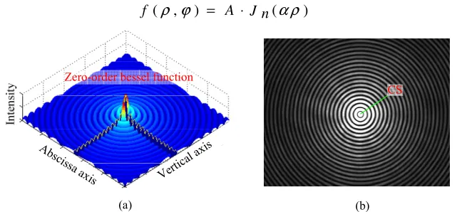
The intensity distribution of an ideal non-diffraction beam follows the zeroth order Bessel function along the radial direction, resulting in a concentric circles fringe, as shown in Fig.1. If the theoretical center position of the non-diffracting beam is [xc,yc], the image f (ρ,φ) of the captured
non-diffracting beam can be expressed as
( , ) ( )
f ρ ϕ = A ⋅ J n α ρ (1)
(b)
Verti cal a
xis
Ab scissa a
xis
(a)
Zero-order bessel function
[image:2.612.147.471.552.701.2]CS
Where A and α are constant and decided by the generated method of non-diffracting beam, ρ is the polar radius distance to the center spot’s coordinate [xc,yc] of non-diffraction grayscale, φ is the
polar angle, as shown in Fig. 2(a).
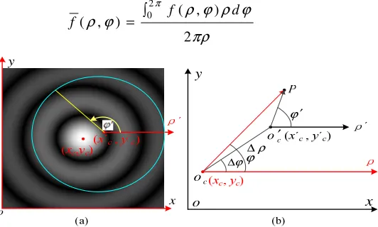
Filtering operations are carried out using the ring in the center spot of the non-diffracting beam to obtain
2
0 ( , )
( , )
2
f d
f
π
ρ ϕ ρ ϕ ρ ϕ
πρ ∫
= (2)
[image:3.612.174.440.146.306.2]o x y ρ ∆ ϕ ∆ ϕ ′ ϕ x y o c o c o′
Figure 2. Polar coordinate transformation: (a) the image of the non-diffracting beam was expanded in the position of ideal center and out of it; (b) the relationship of the polar coordinate in the
common center position and out of it.
If the theoretical center position of the non-diffracting beam is [xc ,yc], the image f (ρ, φf) of the
non-diffracting beam can be expressed as
(
)
( , ) ,
f ρ ϕ = f ρ ϕ (3)
From the correlation operation f (ρ, φf) withf (ρ, φf), we get the normalized dimensionless
coefficient Q(xc ,yc)
2 2 0 1
1 2
2 2
2 2 2 2
0 1 0 1
( , ) ( , )
( , ) 1
( , ) ( , )
c c
r
f f d d
r Q x y
r r
f d d f d d
r r
π
π π
ρ ϕ ρ ϕ ρ ϕ
ρ ϕ ρ ϕ ρ ϕ ρ ϕ
⋅ ∫ ∫ = = ⋅ ∫ ∫ ∫ ∫
(4)When the origin of the polar coordinates [xc, yc] deviate from the common center and move to
[x'c, y'c], as shown in Fig.2(b), according to the polar coordinates translation transformation, we
obtain
(
)
(
)
2 2 2
2 cos( )
sin( ) sin tan
cos( ) cos
f
f f
f
ρ ρ ρ ρρ ϕ ϕ
ρ ϕ ρ ϕ
ϕ
ρ ϕ ρ ϕ
′ ′ ′ = + ∆ + ∆ − ∆ ′ ′ + ∆ ∆ = ′ ′ + ∆ ∆
(5)Where (∆ρ, ∆φ) is the position of origin o'c in polar coordinate ocρ, and assuming that the polar
axis is parallel,
(
)
(
)
1
2 2 2
c c c c
x x y y
ρ ′ ′
∆ =
− + −
, tan 1 c cc c y y x x ϕ − ′ − ∆ = ′ −
. With the approximatecos( )
ρ
≈ρ
′+ ∆ρ
ϕ
′− ∆ϕ
(6)And then the distribution of non-diffraction grayscale can be described as
(
)
{
}
0
( , ) cos
f′ ρ ϕ′ ′ ≈ A J⋅ α
ρ′+ ∆ρ ϕ′− ∆ϕ
(7)Substituting equation (7) into equation (2), we get
(
)
{
}
2
0 0 cos
( , )
2
A J d
f
π
α ρ ρ ϕ ϕ ϕ
ρ ϕ
π
′ ′ ′
⋅ + ∆ − ∆
∫
′ ′ ′ =
(8)From the correlation operation f′(ρ ϕ′, ′) with f′(ρ ϕ′, ′), we get the normalized dimensionless
coefficient Q x
(
c′,yc′)
,let χ ϕ( )
′ = ∆ρcos(
ϕ′− ∆ϕ)
( )
( )
(
)
2 2 0 1 0
1
2 2
2 2 2 2 2
0 1 0 0 1
( , )
,
c c
r
J d d
r Q x y
r r
J d d f d d
r r
π
π π
αρ χ ϕ ρ ϕ
αρ χ ϕ ρ ϕ ρ ϕ ρ ϕ
′+ ′
∫ ∫
′ ′ =
′+ ′ ⋅ ′ ′ ′
∫ ∫ ∫ ∫
[image:4.612.107.487.258.495.2](9)
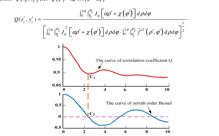
Figure 3.The curve of the correlation coefficient Q with the offset center position ∆ρ.
According to the Cauchy-Schwarz inequality, and from equation (9), the dimensionless coefficient Q is at a maximum and close to or equal to 1, only when the center-coincidence is also the ring-filtering center, or Oc coincides with the common center Oc´of the non-diffracting image.
Analysis of equation (9) and Fig.3 shows that the value of the normalized dimensionless coefficient Q(xc´, yc´) has a peak value (close or equal to one) when the ring-filtering central coordinates[xc´,
yc´] coincide with the defined common central coordinates [xc , yc]. Additionally, Q is a monotonic
function only with the bullseye offset level ∆ρ within the interval [0, 2.405]. A digital integration method was used to solve for the monotone interval, since the Bessel function is a non-integrable equation. Thus, we find the position of the peak value Q(xc´, yc´)in the zeroth order region of the
Bessel function, which means that the center of the non-diffracting beam has been determined.
Algorithm
Using the principles outlined above, an iteration algorithm is designed as follows:
(1) For a given non-diffracting beam patternf( , )ρ ϕ with an assumed initial center, a centrobaric
2 2
0 1 0
1 2 1 2
0 0
( , ) cos ( , ) sin
( , ) ( , )
f d f d
x y
f d f d
π π
π π
ρ ϕ ρ ϕ ϕ ρ ϕ ρ ϕ ϕ
ρ ϕ ϕ ρ ϕ ϕ
∫ ∫
′ = ′ =
∫ ∫ (10)
(2) Ring-filtering is performed for the non-diffracting image with the coordinate as the center.
2
0 1( , )
( , )
2
f d
f
π
ρ ϕ ρ ϕ ρ ϕ
πρ ∫
= (11)
where 2 2
1 1
(x x) (y y)
ρ= − ′ + − ′ is the polar radius and covers the non-diffracting image.
(3) Calculating the correlation of f( , )ρ ϕ with f( , )ρ ϕ , the correlation coefficient
1, 1
( )
Q x′ y′ in
positionx y1′, 1′is obtained.
(4) Steps (2)~(3) are repeated for different intervals of polar radii to obtain a series of arrays
1, 1
( )
Q x y
i ′ ′ , and the peak value of Qi and its corresponding coordinate positionx11′,y11′ ,x12′ ,y12′ … 1N, 1N
x y
′ ′
are found.
Central spot
C
o
rr
e
la
ti
o
n
c
o
e
ff
ic
ie
n
t
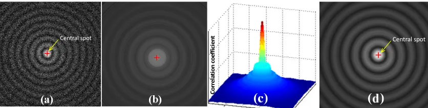
[image:5.612.99.517.294.400.2]Central spot
Figure 4. Calculation procedure of the central spot of non-diffracting beams by digital ring-filtering and circle-matching: (a) original photograph of a non-diffracting beam with variance 0.1 Gauss noisef
(
ρ ϕ,)
; (b) non- diffracting image processed using ring-filtering deviating from the centerspot; (c) correlation coefficient
1, 1
( )
Q x′ y′ calculated in the neighboring interval
1, 1
x y
′ ′ ; (d)
ring-filtering produced in the center spot x y0, 0.
(5) The average of the common center of the non-diffracting imagex y0, 0is computed.
0 2 0 2
1 1
y
N N
i i
i i
x
x
N
y
N
= =
′
′
∑
∑
=
=
(12)Following the above steps, the corresponding results at each stage are shown in Fig. 4.
Numerical Analyses of Noise Sensitivity for the Algorithm
In practice, a non-diffracting beam is influenced by three basic kinds of factors. The first is random light intensity distribution that is generated by laser speckle and electronic noise produced by the image sensor. The second is machining error in the fabrication of the axicon lens, which leads directly to fringe deformation. The third is environmental noise from background illumination, such as pepper and salt noise, etc.
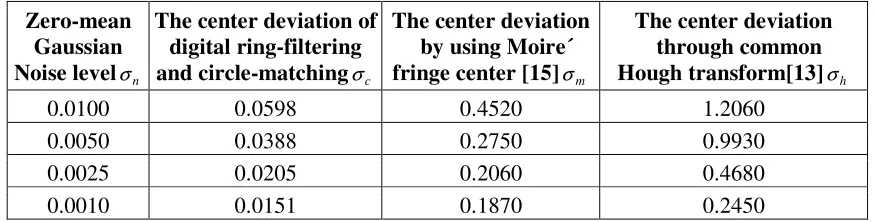
and added it to the measurement image. Finally, the central spot of the non-diffracting image was iteratively calculated. Table 1 lists the simulated results of noise effects for the different algorithm.
Table 1.Numerical simulation of noiseeffectsa in different algorithm.
Zero-mean Gaussian Noise levelσn
The center deviation of digital ring-filtering and circle-matchingσc
The center deviation by usingMoire´ fringe center [15]σm
The center deviation through common Hough transform[13]σh
0.0100 0.0598 0.4520 1.2060
0.0050 0.0388 0.2750 0.9930
0.0025 0.0205 0.2060 0.4680
0.0010 0.0151 0.1870 0.2450
a
c
σ ,
m
σ and
h
σ is the deviation between the calculated position and the designed centre,
respectively, and their units are pixel.
Note that the radial intensity distribution of a non-diffracting beam is roughly inversely related to the radius from the central position, meaning that the intensity of the zeroth order area is much greater than that of the outer fringes. Consequently, when the center intensity is uniform to 1, Gaussian noise with variance σn=0.1 already leads to the gray non-diffracting image which is
heavily polluted. Even so, the digital simulation experiment indicates that the error of the computed center position is less than 0.1 using the method outlined in this paper, which means that the deviation is far less than the size of one sensor element of image sensor. The resolution of the correlation-coefficient based ring-filtering method with subpixel accuracy steady connectivity than other methods, such as digital moiré fringe-scanning method, common Hough transform or centrobaric method, and etc.
Conclusion
Using ring filtering and correlation coefficient calculating, the common center of a non-diffracting beam that is a concentric circle fringe can be determined with subpixel accuracy despite a noisy background. Because of the use of all non-diffracting image data in the process of ring filtering and correlation coefficient calculating, one can achieve not only subelement resolution but also an anti non-circular fringe and concentric circle recognition. The proposed method is a key technique for the application of a non-diffracting beam as a natural reference in engineering.
Acknowledgment
This work is supported by the National Natural Science Foundation of China (Grant no. 61505169), and also was supported by Key projects in Sichuan province department of education (No. 15zd1114), and the natural science foundation of Southwest University of science and technology (No. 14zx7160), and was supported by the Key Project of Fundamental Co-construction of Sichuan Province in China (No. 13zxzk06).973 of Ministry of Science and technology of China (Grant no. 2013CB035405).
References
[1] K.C. Fan and Y. Zhao, Laser straightness measurement system using optical fiber and modulation techniques Int J Mach Tools Manuf, 40, 2073-2081, 2000.
[3] S.T.Lin, A laser interferometer for measuring straightness Opt Laser Technol, 33, 195-199, 2001.
[4] B.Y. Chen, B. Xu, L.P. Yan, Zhang Enzheng and LiuYanna. Laser straightness interferometer system with rotational error compensation and simultaneous measurement of six degrees of freedom error parameters Opt. Express, 23, 9052-9073, 2015.
[5] Durnin J .Diffraction-free beams Phys. Rev. Let, 58, 1499-1501, 1987.
[6] Durnin J. Exact solutions for nondiffracting beams I. The scalar theory. J. Opt. Soc. Am. A, 4, 651-654, 1987.
[7] G.L. Ma and B. Zhao, Y.Y. Fan, Non-diffracting beam based probe technology for measuring coordinates of hidden parts Opt Lasers Eng, 51585-591, 2012.
[8] G.L. Ma and B. Zhao, .Polar transformation-based phase-scanning method for centering a non-diffracting fringe image Opt Commun, 325, 47-53, 2014.
[9] B. Zhao and Z. Li, Diffraction property of an axicon in oblique illumination Appl. Opt. 37, 2563-2568, 1998.
[10] X.B. Zhang, B. Zhao and Z. Li, Measurement method of spatial straightness error using non-diffracting technology J Opt A Pure Appl Opt, 6, 121–126, 2004.
[11] L.P. Zhou, B.Zhao and Z. Li, Theory and Generation of Non diffracting Bessel Beams Optics and precision engineering, 4, 14-19(In Chinese), 1997.
[12] G.L. Ma, G.Y. Zeng and B. Zhao, Arago-Poisson diffraction spot observed in the shadow area of an axicon lens Journal of Optics, 16, 1-6, 2015.
[13] Y.Liu and S. Zhou, Detecting Point Pattern of Multiple Line Segments Using Hough Transformation Semiconductor Manufacturing, 2813-24, 2015.
[14] J.P. Wu, K. Chen and X.H. Gao, Fast and accurate circle detection using gradient-direction-based segmentation J Opt Soc Am A, 30, 1184-1192, 2013.
[15] B. Zhao, Digital Moiré Fringe-Scanning Method for Centering a Circular Fringe Image Appl. Opt, 43, 2833-2839, 2004.
[16] Y. Fan and B. Zhao, Coordinate measurement of hidden parts using an attitude angle sensor and a laser rangefinder Opt Eng, 53, 124101-124101, 2014.
[17] Juárez-Reyes, Salvador Alejandro, Ortega-Vidals Paula and Silva-Ortigoza Gilberto. Wavefronts, light rays and caustic associated with the refraction of a spherical wave by two interfaces: The axicon and the plano-convex parabolic lenses J. Opt. 17, 065604, 2015.