HEWLETT-PACKARD COMPANY Roseville Networks Division
8000 Foothills Boulevard
UP 9000 Series 200 Computer Systems
HP 98624A
HP-IB Interface Card
FliDW
HEWLETT
~~
PACKARD
Installation Note
Printing History
Printing History below identifies the Edition of this Manual and any Updates that are included. Periodically, update packages are distributed which contain replacement pages to be merged into the manual, including an updated copy of this Printing History page. Also, the update may contain write-in instructions.
Each reprinting of this manual will incorporate all past updates; however, no new information will be added. Thus, the reprinted copy will be identical in content to prior printings of the same edition with the user-inserted update information. New editions of this manual will contain new information, as well as updates.
ii
98624-90000
First Edition . . . .. June 1981 Second Edition . . . June 1985
NOTICE
The information contained in this document is subject to change without notice.
HEWLETT-PACKARD MAKES NO WARRANTY OF ANY KIND WITH REGARD TO THIS MATERIAL, INCLUDING, BUT NOT LIMITED TO, THE IMPLIED WARRANTIES OF MERCHANTABILITY AND FITNESS FOR A PARTICULAR PURPOSE. Hewlett-Packard shall not be liable for errors contained herein or for incidental or consequential damages in connection with the furnishing, performance or use of this material.
This document contains proprietary information which is protected by copyright. All rights are reserved. No part of this document may be photocopied, reproduced or translated to another language without the prior written consent of Hewlett-Packard Company.
UP 98624A
UP-IB Interface Card
Installation
The HP 98624A is an HP-[B Interface Card for HP 9000 Series 200 Computers. (HP-IB is Hewlett-Packard's implementation of IEEE 488-1978.) This note describes the procedure for installing the 98624A.
Installing Interface Cards in the Series 200 Backplane
The backplane of a Series 200 computer can contain from 2 to 16 card slots (depending on the model of computer). These card slots come in pairs; each cover plate on the back of the computer covers one such pair of slots. The lower slot of each pair can accept any Series 200 card (interface, memory, or DMA); the upper slot can accept only memory and DMA cards. Thus interface cards must be inserted into the lower slot of a pair.
To install an interface card in the Series 200 backplane, follow these instructions:
1. Set the switches on the card according to the instructions in the section on Configuring the Interface Card.
2. Turn the computer off.
3. Interface cards must go into any of the slots just below a pair of cover bolt holes. Remove the metal backplane covers one by one until you find an empty slot just below a pair of cover bolt holes.
4. The metal plate on the interface card takes the place of a backplane cover. A memory or DMA board may be installed in the slot above the interface card.
5. Slide the interface card into the slot, component side up, until it bottoms against the backplane connector board. Then tighten the thumbscrews until they are finger tight.
6. [f there are no empty slots just below a cover bolt hole pair, you must rearrange the memory boards to accommodate the interface card. Remove any memory board in a slot below a bolt hole pair and re-install it in an empty slot above a bolt hole pair. It is not necessary to change the address of the memory board, as the computer CPU automatically finds the board at its new location.
7. If there are no empty slots, a memory board or interface card must be removed and left out if the new interface card is to be installed. If a RAM memory board is left out, make sure it has the lowest address.
8. Connect the computer to the desired peripheral using an appropriate cable.
Configuring the Interface Card
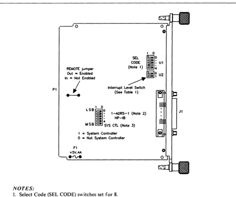
Figure I shows the location of all the configuring switches on the 98624A, in the default (factory set) configuration. In this configuration, the interface card "wakes up" as follows:
I. Not System Controller 2. Interrupt Level 3 3. Select Code 8 4. Primary Address 0
If the default configuration is acceptable, check to make sure that all the switches are set according to the diagram. If you wish to reconfigure the interface, refer to the accompanying drawing and the HP-IB section of your I/O Programming Manual.
2
PI
NOTES:
o
1 0 REMOTE jumper
Out - Enabled In • Not Enabled
CODE SEL ; 0
2: :
Ul (Note 1) :§:4
~
Interrupt Level Switch (See Table 1)
I
---
1 0LSBIO
C I · 1 -AORS-l (Note 2)2: :
HP-IBC l 4
M S
e
C I SYS CTL (Note 3) I=
System Controllero •
Not System Controller Fl+5V .... A
e-ru-e
Igl~
U21. Select Code (SEL CODE) switches set for 8.
Jl
2. Address Switches (l-ADRS-l) set for power-up primary HP-IB address of the card. If you want this card to perform the functions of the computer's internal HP-IB, we recommend that you set the address to 21 if the card is the system controller, or 20 if the card is not the system controller. The driver interprets an HP-IB address of 31 as an address of O.
[image:4.618.55.538.226.628.2]3. The board is not set for system controller.
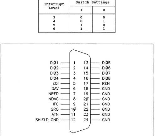
Table 1. Interrupt LeJ1el Switch
Interrupt
Level
3
4
5 6
DI~l
DI~2
DI~3
DI~4
EOI
DAV
NRFD
NDAC
IFe
SRQ
ATN
SHIELD GND
switch settings
1 0 0 1 1
~
1
13
2
14
3
15
4
16
5
17
6
18
7
19
8
2~
9
21
1~
22
1 1
23
12
24
l--/
0 0 1 0 1DI~5
DI¢6
DI~7
DI¢8
REN
GND
GND
GND
GND
GND
GND
GND
[image:5.611.71.565.87.522.2]B
A
U17
12 -<..1 ~H-+-+_+--1
~--,2~-I-+-+-+-1
U4_~
10PI-16 ~---7C<J~ 2 ~ 00 8 U16 U22
P 1-15 6 1 8 1-"'3-->., '--___________________________ ---,-+ ______________ +4 ____ --+-7~B--".2 ~
PI-IB 5 2jY A 13'" i 4
PI-17 4 3 lC I +5V U2
, - - - 1 r 1 -+5V
6 ~O 9 5 114 U22
Ut6
~~3~4-+-~ L -_ _ _ _ _ _ _ _ _ _ _ _ _ _ _ _ ~7
U16 REMOTE
~~6~~~+-~---~---N
~~I-~'I"\ BOO BOI B02 B03 B04 805 808 807
~
rr
9 CONTROL ~ ~Rl 817613415211 ~ ,7 34 B 15217116
150 1 U23 A 244
l~lbl.!.19--- ~~~
Ule Ay 2441
L...,.,="T""".;y"..,...,...--2,....JGr
r----4
12 9 14 7 16 5 lB 3 12 9 14 7 16 5 16 3
PI-77~~---~2~Al U27Bll~I~8~ ____________________________ -+~~~I~ ____________ ~4_+_+-~~~---~--~---+-+-~~~- .--1Q 07 PI-7B 3 A2 B.~1~7---~~1-+---_+-+-r~~1-+-+---4--_+---~~~1-+-+-~~ ______ ~1~1 06
PI-79 4 A3 B 16 12 05
PI-80 5 44 B 15 13 04
PI-81 6 A5 8 14 14 03
PI-82 7 A6 B 13 15 02
PI-83 8 A7 B 12 16 01
P 1-84 9 AB 245 B II 17 DO
G DIR
T9
1,---1 _ _ _ +-++-+---_U2:,,,,,'~;
I
EN3t-L-Ilfl£.,
PI-I <E-____ +-__ .!o..I.!jl 01 EN414 I I J
PI-2 8 02 ENI 13 1
PI-3 2 13 I~9~1~---+---4_--+---~~~4_+---________ .!o..d1 ACCRQ
+'iV
5 4 1213 I 129 147 165 183
1
20 10 30 4~K 9 1 diG Y
1
U9 175 1 ~~--:.::.lg'dI]12G U13 A 244
2G4G3GjG I I
7 1510f2 4 B 11 6 13 2 1~5
L--4~4-~---.--J
U16
31 ~03
~04
PI-4 5 14 126 2 ACCGR
I r---_+--+-~---~--+_---_+~~~~--4_---~8~RS2
~---' I 7 RS 1
I I 6 RSO
PI-51 >---+---~6~12 0 14 9 Ull 10 5 ~ 3 CE
TNT
U5
TMS9914A
L
OAVJ--C-7---~....,. JI-6
'J6 NOAC.f.=5----~_3> JI-8
NRFO 6 JI-7
EOl 8 JI-5
ATN 9 J1-ll
SRCl 10 J1-10
75162 REN~ ( " J!-!7
OI01~3~8~---~19~01 TE
IFC 4 J1-9
DC 1 12 h I -~
OI02 37 18 02 U3 0103 36 17 U::l
0104 35 16 04 0105 34 15 05 0106 33 14 06 0107 32 13 07 75160
OIOB 31 12 08
OAV NoAC NRFo EOI ATN SQR REN IFC 8Al BA2 BA3 8A4 8R/W m:rrs
PI-50 4
1IU250::~
II
~
:
~~IN
PI-52 8 13 011,,1"'6'__ ____ -' L.J..Q U15 13 3 PI-53 1114 0147'--.----0_____ 502 W ~ o---! lC
A B ' -_ _ "I/I_....,R~E.;;.S.;;.E.;..T _ _ _ _ _ _ _ _ _ _ _ _ _ _ - '
P 1- 45 13 I 5 04l-'9~-4---+--~---!---, 1 ~ 2C 1 t:>12--- r_+-+---.--J118
J
19PI-43 2 16 6 14 2Y I
P
ig 1 rN EN 244 0 lB ,..£ ~8'---+-+~-+--~-"-"2<:t2G i>"4'----+-+--+--+---+---=-<:11G U12ot>-Z---11. 12 ~ S10 9 1 6
U 11 ' - - - ' jY 2 b-=5'----______ --.J
S02 13 ~ U 11 J--=-1 __ -+--+-______________ +_~ 155 REF. ITEM +5 GNo
8A1S BA17 BA18 BA19 BA20 BA21 BA22 BA23 502
~ ENt14 11
01~~-r---4--~---~4---+_~-4--~----~---~
l4Pl~2--~---+__+_+---~~---~_4_+~--_4---I~---+_+_~8 5~~Z
I 5
PI-46>---~
U21
SOO 9 8
Lr-ll
D CK 94 D +-__ +---,1:.:2'-10 U 10
15 Q
3 D
13 0
175 CL +5V +5V GNO GNO GNo GNO GNO GNO
I! I! I! I!
Ul U2 U3 U4 U5 U6 U7 UB U9 Ul0 Ul1 U12 U13 U14 PI-85~1
PI-86 +5V
+ Cl C2 Cl0
T22Uf T01U!f.01Uf
PI-13,
14~----~----~--~-PI-21, 22 PI-35, 36 >---PI-39, 40
PI-47, 4B >---Pl-S1, S2>---GNO PI-75,7S
~ P 1-37 »---f.-=-1-'\~3
2~~---~
86
**** **** **** -- -- 6-10 21 -- 3, 4
3 20 10
-- 14 7
-- 40 20
1 22 II
2 14 7
17 14 7 B 16 B 7 16 8
7 14 7
15 16 8
10 20 10 6 14 7
REF. **** U15 U16 U17 U18 U19 U20 U21 U22 U23 U24 U25 U26 U27
ITEM +5 GNo
**** **** ****
11 14 7
14 14 --19 -- 7-12 20 20 10
6 16 8
8 14 7 12 14 7 13 18 6 9 16 14 20 14 20 20 20 10 7 10 10 10 JI-19 JI-20 JI-21 JI-22 JI-23 Jl-24
~
JI-18 GNO GNo GNO GNO GND GND GNOr---~«_,.) J 1-12 SH I EL 0
J
GNOU
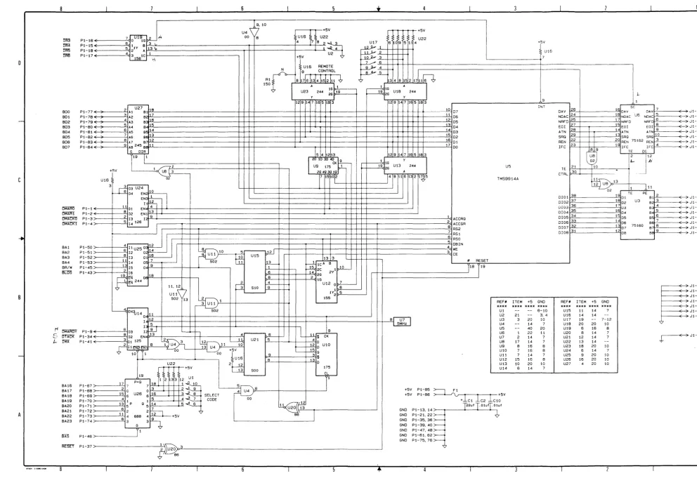
Figure 3. H P 98624A Schematic Diagram
B
[image:7.1228.150.1143.30.711.2]MANUAL PART NO. 98624-90000 E0685 Printed in U.S.A.
June 1985
FliD'l
HEWLETT
a:a11
PACKARD