Systems Reference Library
System Operation Reference Manual
IBM 1440 Data Processing System
This publication contains the instruction set for the IBM 1440 and the formula for calculat-ing the execution time of each instruction. The operation code for every instruction is given in actual and mnemonic form, with ex-amples of each.
The instructions and applicable timings for the input/output printer on the IBM 1447 Con-sole are discussed.
For general information on units attached to the 1440, refer to the IBM 1440 Bibliography, Form A24-3005. For instructions and applic-able timings for attached units, see:
• Miscellaneous Input/Output Instructions (1440), Form A24-3117.
• Tape Input/Output Instructions (1401, 1440, 1460), Form A24-3069.
• Disk Storage Input/Output Instructions (1401, 1440, 1460), Form A24-3070.
Preface
This publication is a reference text for the IBM 1440
Data Processing System. It provides a detailed
explan-ation of the instructions used by the system to manipu-late data. Detailed explanations of the instructions used with the console input/output printer when it is attached to the system are also included. The reader
should be familiar with the IBM 1440 Systems
Sum-mary, Form A24-3006, and the various publications on
applied programming material, such as Autocoder.
The manual is divided into these sections:
• Introduction
• Arithmetic Operations • Logic Operations • Data-Moving Operations • Miscellaneous Operations • Edit Operation
• IBM 1447 Console Operations
The sections are independent and do not have to be used in the order in which they appear.
The publication is intended for programmers and systems personnel who have a general knowledge of
the IBM 1440 Data Processing System and who require
a reference text for detailed information. It can also be used as a training aid in the instruction of program-mers and operators,
It should be noted that other publications referenced here are, in most cases, prerequisites for a complete understanding of the material presented in this publi-cation.
This publication, Form A24-3116-0, is a major revision and consolidation of the applicable material from:
A26-5666, and includes the applicable material from the following Technical Newsletter:
N24-0062
The original publication and the applicable Technical News-letter are obsoleted by this publication.
This publication, Form A24-3116-0, also obsoletes thc console I/O printer portions of:
A26-5667
Refer to IBM 1440 Bibliography, Form A24-3005, for other publications.
Contents
Introduction ... 5
Stored Program Instructions ... 6
IDM 1441 Processing Unit ... 8
Internal Checking ... 10
Addressing ... 10
Address Modification ... 15
System Operations.... ... ... ... 18
Arithmetic Operations ... 18
Arithmetic Instructions ... 20
Logic Operations ... 24
Logic Instructions ... 24
Data Moving Operations ... 27
Data Moving Instructions ... 27
Miscellaneous Operations ... 32
Miscellancous Instructions ... 32
Edit Operation ... 36
IBM 1447 Console Operations ... 39
Console Instruction Format ... 39
IDM 1447 Console Instructions ... 39
Console I/O Printer Timing ... 41
Appendix ... 42
Index of 1440 Instructions ... 43
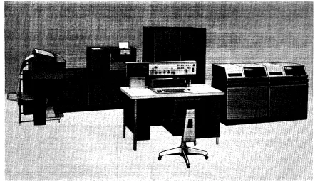
The IBM 1440 Data Processing System (Figure 1) rep-resents a major advance in low-cost data processing
systems. The IBM 1440 offers small companies the
functional capabilities of large data processing sys-tems, but at speeds and costs in keeping with their needs and abilities. The input and output devices of the 1440 enable it to be effective in system areas where there has long been a need for a data processing system but not the volume of work to justify such a system. Processing methods of the 1440 are similar to
those of the IBM 1401 Data Processing System.
The IBM 1440 is a solid-state system with compact components and input/output devices that enable it to be located in an area of approximately 16' x 22'. In addition to its features of compactness and low-cost, the 1440 presents a new concept in data processing with the introduction of the removable disk pack.
In 1953, the introduction of IBM magnetic tape
systems provided data processing systems with the ability to process large volumes of input and output data at very high speeds. Magnetic tape offers the advantage of providing virtually unlimited storage capacity. In 1956, the RAMAC® disk file introduced a new concept in data processing, permitting, as it did, storage of large volumes of data that were accessible in a random sequence.
The IBM 1311 Disk Storage Drive for the IBM 1440 Data Processing System provides virtually unlimited random and sequential access storage. A disk pack containing 2,000,000 characters of information can be removed from the 1440 system and another pack put into its place in one to two minutes. This operator-removable disk pack combines the large-volume and sequential-processing advantages of tape systems with the random-access abilities of a RAMAC file.
The ease of mobility of a disk pack (the weight of the pack is less than 10 pounds) and the simplicity of its removal from the drive means that 2,000,000 char-acters of data can be placed in the system within seconds. Data can be organized in the disk pack in
random or sequential order; regardless of how the
data is located on the disk pack, it can be retrieved by the system in a random or sequential order with equal facility, depending on individual requirements. Up to five disk drives, each equipped with one disk pack, can be attached "on line" to provide 10,000,000
char-IBM 1440 Data Processing System
acters of information available at one time (equiv-alent to 125,000, 80-column punched cards).
The 1440 is primarily a disk-storage oriented system, providing a group of balanced input/output devices
to work in conjunction with the IBM 1441 Processing
Unit and with the IBM 1311 Disk Storage Drive. For
operations that require extensive calculating ability and do not need disk storage, the 1440 can function as a card system.
The IBM 1440 is available in various configurations to satisfy the requirements of individual lJsers. It can be ordered to meet the basic requirements of an ac-counting system, and then increased in size as data
processing requirements increase. If the .1440 is
ex-panded to its maximum size and data processing re-quirements continue to grow, procedures and systems
developed for the IBM 1440 can be readily adapted
for processing on the medium-size IBM 1401 Data
Proc-essing System. With continued expansion and growth,
adaptation to larger equipment such ~s the IBM 1460
and 1410 Data Processing Systems can be'made.
This is why we refer to the 1440 as a member of the 1400-series family.
The Stored Program
The IBM 1440 Data Processing System performs its
functions by executing a series of instructions at high speed. A particular set of instructions, . designed ~o solve a specific problem, is known as a program.
Be-cause the 1440 stores its instructions internally, it is called a stored program system.
The 1440 system normally executes instructions se-quentially. The system can also skip over a particular group of instructions, or otherwise change the se-quence of the program. Branch instructions are pro-vided in the system to make it possible to alter the program and take the next instruction from another area of the stored program. This function also makes it possible to repeat an instruction, or group of instruc-tions, as often as desired.
A series of programmed tests determines the logical path of the program. These tests are made at various points in the program to control the course of pro-gram step execution for specific condItions .that can
Variable Word Length
Stored programming involves the concept of words.
A 1440 word can be a single character, or a group of characters, representing a complete unit of informa-tion. Because IBM 1440 words are not limited to a specific number of storage positions - i. e., have vari-able word length - and because each position of core . storage is addressable, each word occupies only the number of core-storage locations actually needed for the specific instruction or data field.
WORD MARKS
The use of the variable-length instruction and data format requires a method of determining the instruc-tion and data-word length. This identificainstruc-tion is pro-vided by a word mark. Word marks are illustrated by underlining the characters with which they are associated.
The word mark serves several functions:
1. Indicates the beginning of an instruction. 2. Defines the size of a data word.
3. Signals the end of execution of an instruction. The rules governing the use of word marks are:
1. Predetermined locations for word marks are as-signed in planning the program. These predeter-mined word marks are normally expected to remain in these locations throughout the complete pro-gram. The word marks are set into storage loca-tions by a loading routine.
2. Word marks are not moved with data during proc-essing, except when a load instruction (see No.5 below) is used.
3. For an arithmetic operation, the B-field must have a defining word mark, and the A-field must have a word mark only when it is shorter than the B-field. 4. A load instruction moves the word mark and data from the A-field to the B-field, and clears any other word marks in the designated B-field, up to the length of the A-field.
5. When moving data from one location to another, only one of the fields need have a defining word mark, because the move instruction implies that both fields are the same length.
6. A word mark must be associated with the high-order character (operation code) of every instruc-tion.
7. The 4-character BRANCH UNCONDITIONAL instruction, the 7 -character SET WORD MARK, and CLEAR STORAGE AND BRANCH instructions are the only instructions that can be followed by a blank without a word mark. All other instructions must be followed by a word mark.
Two operation codes are provided for setting and clearing word marks during program execution.
Stored
Program Instructions
All machine functions are initiated by instructions from the 1440 stored program. Because the 1440 uses the variable-word-Iength concept, the length of an in-struction can vary from two to eight characters, de-pending on the operation to be performed.
Instruction Format
Mnemonic Op Code A-or I-address B-address d-character
X X XXX XXX X
~1 nemonic. This is the mnemonic operation code that is used by the Autocoder processor program to des-ignate the actual machine operation code.
Op Code. This is always a single character that defines the basic operation to be performed. A word mark is always associated with the operation code posi-tion of an instrucposi-tion.
A-Address. This always consists of three characters. It can identify the units position of the A-field, or it can be used to select an input/output unit (card read-punch, disk storage unit, data transmission unit, paper tape reader, printer, tape punch, etc.).
I-Address. Instructions that can cause program branches use the I -address to specify the location of the next instruction to be executed if a branch occurs.
B-Address. This is a 3-character stvrage address that identifies the B-field. It usually addresses the units position of the B-field, but in some operations (such as move record or input/output operations it speci-fics the high-order position of a record-storage area.
d-Character. The d-character is used to modify an operation code. It is a single alphabetic, numerical, or special character, positioned as the last character of an instruction.
Examples of the five combinations possible in vari-able-length instructions are shown in Figure 2.
Instruction Descriptions
Specific instructions have been described in a standard format:
NUMBER OF
POSITIONS OPERATION INSTRUCTION FORMAT
2 SELECT STACKER Op code d-character
.!5.. 2
4 BRANCH Op code I-address
.! 400
5 BRANCH IF Op code I-address
INDICATOR ON .! 625
7 ADD Op code A-address
A 072
8 BRANCH IF Op code I-address
CHARACTER EQUAL ~ 650
Figure 2. IBM 1440 Instruction Formats
Instruction Format. This is the format of the particular instruction described. The mnemonic operation code used in the IBM Autocoder is given.
Function. This is the function of the instruction.
Word Marks. This is the effect of the word marks with regard to data fields.
Timing. This is the formula to be used in calculating the timing of the instruction. Key to abbreviations used in the formulas is shown in Figure 3.
Notes. These are special notations or additional infor-mation pertaining to the operation.
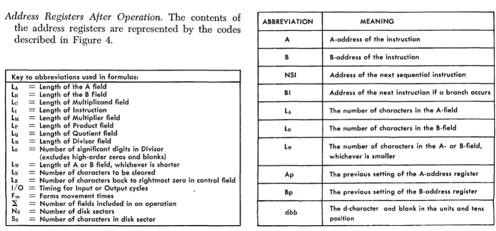
Address Registers After Operation. The contents of the address registers are represented by the codes described in Figure 4.
Key to abbreviations used in formulas: LA Length of 'the A field LB Length of the B Field La Length of Multiplicand field LI Length of Instruction LM Length of Multiplier field Lp Length of Product field LQ Length of Quotient field LR Length of Divisor field
Ls Number of significant digits in Divisor (excludes high-order zeros and blanks) Lw Length of A or B field, whichever is shorter Lx Number of characters to be cleared
Lz Number of characters back to rightmost zero in control field
1/0
=
Timing for Input or Output cycles Fro = Forms movement times~ = Number of fields included in an operation Ns Number of disk sectors
Ss
=
Number of characters in disk sectorFigure 3. Timing Formula Coding
d-r.haracter /
B-address
423
B-address d-character
080 4
Example. A practical application of the instruction is described and shown as a label for the 1440 Auto-coder language. With the label is the actual machine address in parentheses. It is not necessary for the programmer to know the actual address of a label when writing the program. The processor program assigns the actual address during the program as-sembly.
Assembled Instruction. This is the actual machine lan-guage instruction that is assembled by the Auto-coder processor program from the symbolic entries shown in the example.
ABBREVIATION MEANING
A A-address of the instruction
B B-address of the instruction
NSI Address of the next sequential instruction BI Address of the next instruction if a branch occurs LA The number of characters in the A-field
LB The number of characters in the B-field Lw The number of characters in the A- or B-field,
whichever is smaller
Ap The previous setting of the A-address register Bp The previous setting of the B-address register
dbb The d-character and blank in the units and tens
position
[image:7.613.65.570.469.705.2]Figure 5. IBM 1441 Processing Unit
IBM 144
J
Processing Unit
The IBM 1441 Processing Unit (Figure 5) is the con-trolling center of the IBM 1440 Data Processing System. The processing unit can be divided into two sections: 1. The arithmetic-logical section
2. The control section
The arithmetic-logical section performs such op-erations as addition, subtraction, transferring, com-paring, and storing. By adding the multiply-divide special feature, the 1441 can perform direct multipli-cation and division. This section also has logical ability - the ability to test various conditions encoun-tered during processing and to take the action called for by the result.
The control section directs and coordinates the entire system as a single multipurpose machine. These functions involve controlling the input/output units and the arithmetic-logical operation of the processing unit, and transferring data to and from storage. This section directs the system according to the procedure originated by its human operators.
Magnetic Core Storage
The IBM 1441 Processing Unit houses the magnetic-core storage area (Figure 6) that is used by the 1440 system for storing the instructions and data. The data in each core-storage position is available, in 11.1 micro-seconds and the design of the core-storage 'control cir-cuits makes each position individually addressable. This means that an instruction can designate the exact storage locations that contain the data needed for that step.
The physical make-up of each core-storage location enables the IBM 1441 to perform arithmetic operations directly in the storage area. (This is called add-to-storage logic.)
Language
In the punched-card area of data processing, the lan-guage of the machine consists of holes punched in a card. As data processing needs increase, the basic card language remains the same. But in the transition from unit-record systems to the IBM 1440 Data Processing System, and from there to other computer systems, an-other faster, more flexible machine language emerges.
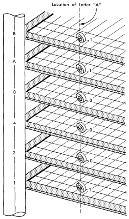
Just as each digit, letter in the alphabet, or special character is coded into a card as a punched hole or a combination of punched holes, it is coded into mag-netic storage as a pattern of magnetized spots.
Figure 7. The Letter A Represented in Binary-Coded-Decimal Form in Core Storage
Many different code patterns can be set up. The internal code used in the IBM 1440 Data Processing System is called binary-coded decimal (Figure 7). All data and instructions are translated into this code as they are stored.
The numbers 0 through 9 are represented by a single bit, or a combination of bits designated 1, 2, 4, 8. Disregarding the C- or check bit, bits 2 and 8 stand for 0, bits 1 and 2 for 3, bits 1 and 4 for 5, bits 2 and 4 for 6, bits 1, and 2, and 4 for 7, and bits 1 and 8 for 9. o Letters and special characters. are represented by a combinations of numerical bits (8421) and zone bits (BA). B- and A-bits, in combination, correspond to the 12-zone punch. The B-bit corresponds to the 11-zone punch, and the A-bit to the O-11-zone punch. The letter C, for example, which is the third letter in the 12-zone of the alphabet (card code 12-3), is a combina-tion of BA21 bits. BA is the same as 12, and 21 is the same as 3.
This covers six of the seven possible bits that are used to represent a character. The seventh bit (C) is a
built-in checking feature that the computer automa-tically supplies.
Note that the check bit is not part of the character configuration when the number of BA8421 bits that represent the character is odd. It appears only for those characters where the number of bits BA8421 is even. The automatic inclusion of the check bit changes the configuration of the character from an even num-ber of bits to an odd numnum-ber of bits. Thus, all char-acters shown in Figure 64 are shown in the odd-parity
mode.
Information introduced into the system is trans-lated to the binary-coded-decimal form for use in all data flow and processing from that point on, until it is translated into printed output as reports and docu-ments are written, or converted to punched-card code, for punched-card output. Converting input data to the 1441 internal code, and subsequently reconverting, is completely automatic.
Processing
Processing is the manipulation of data from the time it is introduced to the system as input until the de-sired results are ready for output. The following func-tions are performed in the IBM 1441 Processing Unit.
Logic
The logic function of any kind of data processing system is the ability to execute program steps; but even more, it is the ability to evaluate conditions and select alternate program steps on the basis of· those conditions.
In unit-record equipment, an example of this logic is selector-controlled operations based on an X-punch or No X-punch, or based on a positive or negative value, or perhaps based on a comparison of control numbers in a given card field.
Similarly, the logic functions of the 1440 system control comparisons, branching (alternate decisions similar in concept to selector-controlled procedures), move and load operations (transfer of data or instruc-tions), and the general ability to perform a compli-cated set of program steps with necessary variations.
Arithmetic
[image:9.618.69.275.68.418.2]Editing
As the term implies, editing adds significance to out-put data by punctuating and inserting special charac-ters and symbols. The 1440 system has the ability to perform this function, automatically, with simple pro-gram instructions.
Internal Checking
Advanced circuit design is built into the 1440 to as-sure accurate results. Self-checking with the system consists of parity and validity checking.
Parity Checking
The IBM 1441 checks characters at various locations in the unit for odd-bit configurations. The 6-bit, bi-nary-coded-decimal internal language used by the ]440 also has a check bit for odd-bit checking pur-poses, and a word-mark bit. The check bit is added to all characters that would otherwise have an even number of bits.
Example: A character P has a binary-coded decimal
equivalent of B 4 2 l. The check bit is added to give this character an odd number of bits (C B 4 2 1).
If the character has a word mark associated with it, the word mark is included in the test for odd-bit parity.
Example: If the character P has a word mark, the check bit is not added because the bit configuration is odd (\VM B 4 2 1).
Whenever a parity error occurs, a console light turns on, indicating the place where the error occurred (see IBM 1447 Console, Form A24-3031).
Validity Checking
Validity checking is performed to detect illogical bit combinations within the systems. The type of validity checks performed are:
1. The output from the adder is checked for a logical numeric code.
2. The operation register is checked so that only valid operation codes are processed.
3. The storage address register is checked to make sure the core-storage addresses are valid addresses within the core-storage address range of that par-ticular processing unit. Depending on the core-storage size, the units and/or hundreds address positions contain zone bits that specify blocks of
addresses. (Refer to Addressing System section for detail information.) These zone-bit combinations are checked to make sure the combinations are addressing an installed core-storage address. A check is made to see if the lower or upper limits of core storage have been passed. This check is called an end-around check and is made at all times except for three special operations. The modi-fication of the low-order position of core storage by - 1, except during a clear storage operation, or the modification of the high-order position of core
stor~ge by
+
1, except during storage scan and storage print out operations, causes an invalid operation and a system stop.4. Of the more than 4,000 bit configurations possible when read from a card, only 64 are recognizable characters. All other bit configurations are con-sidered invalid during the data transfer from the read side of the card read-punch into core storage. A detected check condition turns on the card read validity check light. Depending on the I/O check stop switch setting on the 1447, the system also stops or a program-testable indicator is set ON.
Addressing
Instructions and data used for processing in a 1440 system are kept in the storage area. Each core-storage position in the area has its own unique ad-dress. The IBM 1441 Processing Unit is available with four different core-storage capacities. The 1441, Model A3, contains 4,000 core-storage positions, and Model A4 contains 8,000 core-storage positions. Model A5 contains 12,000 core-storage positions, and Model A6 contains 16,000 core-storage positions.
Addressing System
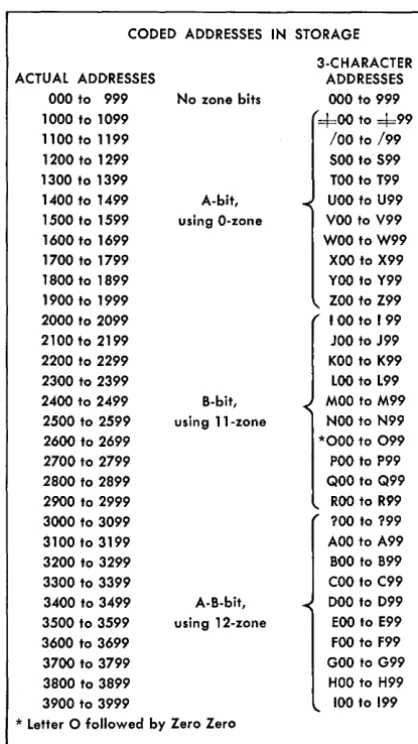
Every core-storage position in the IBM 1440 Data Processing System can be addressed with a 3-character address: To address 16,000 core-storage positions with numbers only, various zone-bit configurations are added over the hundreds position and units position of the address.
CODED ADDRESSES IN STORAGE
3-CHARACTER ACTUAL ADDRESSES ADDRESSES
000 to 999 No zone bits 000 to 999
1000 to 1099 =i=00 to =i=99 1100 to 1199 /00 to /99
[image:11.617.71.280.66.438.2]1200 to 1299 SOO to S99 1300 to 1399 TOO to T99 1400 to 1499 A-bit, UOO to U99 1500 to 1599 using O-zone Voo to V99 1600 to 1699 WOO to W99 1700 to 1799 XOO to X99 1800 to 1899 YOO to Y99 1900 to 1999 ZOO to Z99 2000 to 2099 100 to 199 2100 to 2199 JOO to J99 2200 to 2299 KOO to K99 2300 to 2399 LOO to L99 2400 to 2499 B-bit, MOO to M99 2500 to 2599 using ll-zone NOO to N99 2600 to 2699 *000 to 099 2700 to 2799 POO to P99 2800 to 2899 QOO to Q99 2900 to 2999 ROO to R99 3000 to 3099 ?OO to ?99 3100 to 3199 AOO to A99 3200 to 3299 BOO to B99 3300 to 3399 COO to C99 3400 to 3499 A-B-bit, DOO to D99 3500 to 3599 using 12-zone EOO to E99 3600 to 3699 FOO to F99 3700 to 3799 GOO to G99 3800 to 3899 HOO to H99 3900 to 3999 100 to 199 * Letter 0 followed by Zero Zero
Figure B. Core-Storage Address Coding
ZONE BITS OVER ACTUAL ADDRESSES HUNDREDS POSITION
0000 to 0999 No Zone Bits 1000 to 1999 A-Bit (Zero-Zone) 2000 to 2999 B-Bit (ll-Zone) 3000 to 3999 AB-Bits (l2-Zone)
4000 to 4999 No Zone Bits
5000 to 5999 A-Bit (Zero-Zone) 6000 to 6999 B-Bit (ll-Zone) 7000 to 7999 AB-Bits (12-Zone)
8000 to 8999 No Zone Bits 9000 to 9999 A-Bit (Zero-Zone) 10000 to 10999 B-Bit (ll-Zone) 11000 to 11999 A B-Bits (12-Zone)
12000 to 12999 No Zone Bits 13000 to 13999 A-Bit (Zero-Zone) 14000 to 14999 B-Bit (ll-Zone) 15000 to 15999 AB-Bits (12-Zone)
Figure 9. 1440 Addressing System
core-storage positions (2000-2999). Both the A- and the B-bit over the hundreds position of the address specify another group of 1,000 core-storage positions (3000-3999). By using these zone-bit combinations, 4,000 positions of core storage can be addressed with a 3-character address (Figure 8).
The same principle used to specify the various 1,000-blocks of core storage is also used to specify core-storage blocks of 4,000 positions. The zone-bit configuration over the units position specifies which block of 4,000 core-storage positions is being ad-dressed.
No A- or B-bit over the units position specifies the 4,000-block in core storage that contains positions 0000-3999. An A-bit over the units position specifies the 4,000-block in core storage that contains positions 4000-7999. A B-bit over the units position specifies the 4,000-block in core storage that contains positions 8000-11999. Both the A- and the B-bit over the units position specifies the 4,000-block in core storage that contains positions 12000-15999. By combining the 3-digit address with zone-bit combinations over the hundreds and/or units position, it is possible to ad-dress 16,000 core-storage positions (Figure 9).
Data-Field Addressing
A data field in core storage is addressed by specifying the low-order (units) position of the field in the A-or B-address of the instruction .. The data field is read from right to left until a word mark in the high-order position is sensed.
ZONE BITS OVER
UNITS POSITION 3-CHARACTER ADDRESSES
No Zone Bits 000 to 999 No Zone Bits ::fOO to Z99 No Zone Bits 100 to R99 No Zone Bits ?OO to 199
A-Bit (Zero-Zone) 00=1= to 99Z
A-Bit (Zero-Zone) =t=0=t= to Z9Z A-Bit (Zero-Zone) 10=1= to R9Z
A-Bit (Zero-Zone) ?o=l= to 19Z
B-Bit (ll-Zone) OO! to 99R B-Bit (ll-Zone) =1=01 to Z9R B-Bit (ll-Zone) 101 to R9R B-Bit (ll-Zone) 101 to 19R
Instruction addressed by high-order position
STORAGE
400 401 402 403 404 405 ADDRESS
INSTRUCTION ~ 5 4 2 5 6
'
-The word mark associated with the next sequential in-struction (NSI) stops the reading of this inin-struction.
STORAGE
ADDRES~
DATA
~
t'
6 537 538
0 2
539 540
5 3
y -A-field
Word mark identifies high-order position of A-field.
A-address
f
B~~
~E
B-address
STORAGE ADDRESS 553 554 555 556 557 5
--- .
DATA Q 4 6 0 1 2
5 1 1- -.-559 .. --- " - -5 l E o --- -.. 561 -.
---3 1 ~
y B-field
Word mark identifies high-order position of B-field.
Figure 10. Data and Instruction Addressing
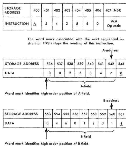
Instruction Addressing
An instruction in core storage is addressed by giving the high-order (operation code) position of the instruc-tion. All operation codes must have a word mark. (This word mark is normally set by the loading routine when the instructions are loaded.) The machine reads an instruction from left to right until it senses the word mark associated with the next sequential instruction. The final instruction in the program must have a word mark set at the right of its low-order position. (The word mark is not needed if the instruction is UNCON-DITIONAL BRANCH, SET WORD MARK, or CLEAR STORAGE.)
Example: Instruction address 400 (Figure 10)
con-tains the operation code for the following instruction:
Op Code A
A-address 542
B-address 560
When this instruction is executed, the data in the A-field is added to the data in the B-field:
0025347 04601231 . -04626578
Core-Storage Area Assignment
There are two areas in core storage that are used for specific purposes. Core-storage positions 001-081 are used in conjunction with a program-load operation and core-storage positions 087-089, 092-094, and 097-099 are used as three index registers when the indexing and store address register special feature is used, All other core-storage positions are always available for normal use, and the areas just mentioned can be used for other system operations when they are not being used as specified.
1440 Register Operation
The IBM 1440 Data Processing System operates on and processes data to produce a desired result by cxecuting a series of instructions. A series of instruc-tions designed to solve a problem is known as a
program. Because these instructions are retained in
core storage, it is more properly called a stored pro-gram.
The processing unit must interpret an instruction and perform the function prescribed by the instruction. To do this, various types of devices that are capable of receiving information, storing it, and t(ansferring it as directed by control circuits are used. These de-vices are known as registers. The 1440 has seven regis-ters, four are address registers and three are character registers (Figure 11).
j - - j
~ Core f----..- B A ~
Storage Register -.. Register
I
-
-Storage Op
Address
-
RegisterRegister
~
t
I-Address A-Address B-Address Register Register Register
~
,
[image:12.617.44.290.81.366.2] [image:12.617.306.551.468.696.2]ADDRESS REGISTERS
There are four address registers in the IBM 1441 Proc-essing Unit. One register controls the program se-quence, and two other registers control the data trans-fer from one storage location to another. The fourth register specifies which storage location is active dur-ing a particular storage cycle.
I-Address Register. The 1- (Instruction) address regis-ter always contains the storage location of the next instruction character to be used by the stored pro-gram. The number in this register is increased by one as the instruction is read from left to. right.
A-Address Register. The A-address register contains the storage address of the data in the A-address portion of an instruction. Normally, as the instruc-tion is executed, the number in this register is de-creased by 1 after each storage cycle that involves the A-address.
NOTE: If the A-address portion of the instruction does not contain a core-storage address (for example % Gx) the con-tents of the A-address register are not altered as the instruc-tion is executed.
B-Address Register. This register contains the storage location of the data in the B-address portion of an instruction. Normally, as a storage cycle involving the B-address is executed, the storage address in the B-address register is decreased by 1.
Storage-Address Register. The storage-address regis-ter always contains the address of the core-storage position that will be involved in any data movement during that particular machine cycle.
CHARACTER REGISTERS
The A- and B-character registers and the Op-register are single-character registers used to store data during the execution of an instruction.
Op-Register. The Op- (Operation) register stores the operation code of the instruction in process for the duration of the operation. The operation code is stored in BCD code, including the check bit but excluding the word mark.
B-Register. Each character leaving core storage enters the B-register. The character is stored in 8-bit form (BCD code, check bit, and word mark). The B-register is reset and filled with a character from core storage on every storage cycle.
A-Register. The A-register is reset and filled with the character from the B-register during each storage cycle that involves the A -address, and during all
instruction cycles except the first and last 1- (Instruc-tion) cycle of each instruction. Data is stored in 8-bit form
NOTE: Information can be written back into core storage directly from either the A- or B-register.
Figure 12 shows the I-phase of an operation and gives a detailed schematic for loading a 7-character instruction in the operation-code register, in the A-and B-registers A-and in the 1-, A-, A-and B-address registers. Eight storage cycles are required to load the complete instruction in the register. Each stor-age cycle requires .0111 ms.
NOTE: The A- and B-address registers contain 3-character addresses. The addresses shown in this schematic are 4-digit addresses because the storage display lights on the console show 4-digit addresses. Refer to Figure 8 for the relationship between 3- and 4-digit addresses.
Chaining Instructions .
In some programs, it is possible to perform a series of operations on several fields that are in consecutive storage locations. Some of the basic operations, such as· add, subtract, move, and load, can be chained so that less time is required to perform the operations, and space is saved in storing instructions. Here is an example of the chaining technique: assume that four 5-position fields stored in sequence are to be added to four other sequential fields. This operation could be done using four 7 -character instructions:
A 700 850 A 695 845 A 690 840 A 685 835
At the completion of the first instruction, the A-address register contains 695 and the B-A-address regis-ter contains 845. These are the same numbers that are in the A- and B-addresses in the second instruction. (Executing the second and third instructions also re-sults in A- and B-addresses that are the same as the A -and B-addresses of the third and fourth instruc-tions.) Eighty storage cycles would be required to execute these instructions, thus using up .888 ms. Also, 28 storage positions are required to store these instruc-tions.
By taking advantage of the fact that the A- and B-address registers contain the necessary information to perform the next instruction, this same sequence of operations can be executed as follows:
~ 700 850
CYCLE OPERATION
I-Op The operation code enters the B-register and the Op-register.
H
1-2
1-3
1-4
Because this is the first I-cycle, the A-register is undisturbed.
The A-address register is reset to blanks during the first part of the cycle for all instructions. The B-address register is reset to blanks during the first part of the cycle for all operations except Move, Load, Store A- and Store B-address Register opera-tion. During the 1-1 cycle, the second instruction character (first character of the A-address) enters the thousands and hundreds positions of the A- and B-address registers and the A-register by the way of the B-register.
The third character of the instruction enters the tens posi-tion of the A- and B-address registers, and the A-register through the B-register.
The fourth instruction character enters the units position of the A- and B-address registers, and the A-register through the B-register.
The B-address register is reset at the beginning of this cycle. The fifth instruction character (first character of the B-address) enters the hundreds position of the B-address register, and the A-register through the B-register.
Instruction
l
AI
5I
6I
7I
TJ
1I
21
s
1
Location 119711981199\20012011202j 2031204\I Register B Register A Register
101119171
W
GJ
Cyde 1OP Register A Address Register B Address Register
W
\ ?(? I?(?I
I ?111?(? 1I Register B Register A Register
\OPI
918 \~
o
Cycle 2OP Register A Address Register B Address Register
10151blb \
~J
I Register B Register A Register
1°1119191
GJ
GJ
Cycle 3OP Register A Address Register B Address Register
W
10(5!6Ib \ 1015161 b II Register B Register A Register
1 °121°10 I
[2]
G
Cycle 4OP Register A Address Register B Address Register
W
1 01516171 10151617 1I Register B Register A Register
I
°1 21°(1 ][2J
~
Cycle 5OP Register A Address Register B Address Register 1 0/51617 \
Dliciil
~----+---.---~---~
1-5
1-6
1-7
The sixth instruction character goes to the tens position of the address register, and the A-register through the B-register.
The seventh character of the instruction (last character of the B-address) enters the units position of the B-address register and the A-register through the B-register.
The first character of the next instruction enters the B-register only. Because this is the last I-cycle for this instruc-tion, the A-register and the Op-register, the A- and B-address registers are undisturbed. The detection of a word mark associated with this character signals the ma-chine that this is the Op code for the next instruction. The loading operations stops, and the instruction that was just loaded is executed. Note that the I-address register con-tains the address of the high-order position of the next sequential instruction.
Figure 12. Instruction Loading Schematic
I Regisfer
10 1210121
OP Register
I Regisfer
10,2,0,3
I
OP Register
I Register
1°121° 141
OP Register
W
B Register A Register
[iJ
[2J
Cycle 6A Address Register B Address Register
I °1516171 /113111 b
I
B Register A Register
I2J
o
Cycle 7A Address Register B Address Register
/°/
51617 1 /1,3,1/2I
B Register A Register
Cycle 8 A Address Register B Address Register
[image:14.621.51.549.62.697.2]Connecting instructions together in this manner is
called chaining. The first add instruction contains both
the A- and B-addresses. The following three instruc-tions contain only the operation code for those in-structions. The A- and B-addresses are the results left in the A- and B-address registers from the previous instruction. This type of operation requires 62 storage cycles, and takes .688 ms to execute. Storing these chained instructions requires only ten storage posi-tions.
The ability to chain a series of instructions does not depend on the use of the same operation code. Chained instructions may have various Op codes. To be operated on, the A-fields must be in sequence, and
the B-fields must be in sequence. Example:
A 900 850
.M.
A
M
Assume that the data fields are each ten characters long:
The ten characters at location 900 were added to 850. The ten characters at location 890 were moved to 840. The ten characters at location 880 were added to 830. The ten characters at location 870 were moved to 820.
The description of each instruction includes the contents of the address registers after the operation has been performed. Figure 4 shows the abbreviations that indicate the contents of these registers.
By using this information, the programmer can de-termine the status of the registers and decide whether chaining is practical in specific cases.
NOTE: Instructions that don't contain core-storage addresses cannot be chained. For example, M % Gn xxx R is a READ CARD instruction. The card read-punch is signaled as the machine reads the instruction. Although the A-address register contains % 7n after the operation, chaining is impossible because the machine does not select the unit from the contents of the A-address register.
Most single-address instructions Op code and an A-address) cause the A-address to be inserted in both the A-address and B-address registers (for example, A xxx. However, executing a MOVE, LOAD, or a STORE B-ADDRESS REGISTER instruction does not disturb the B-address register, and permits the programmer to use the previous contents of that register as part of the instruction.
All no-address instructions (Op code and I -address) depend on whether the indexing and store address register special feature is installed on the system:
l. With the special feature installed, the B-address register contains the address of the next sequential instruction, if a branch occurs.
2. Without the special feature installed, the B-address register is cleared to blanks whenever a branch occurs.
Address Modification
It becomes necessary in some 1440 programs to per-form the same operations repetitively, with a change only in the A- or B-address. Changing of an address while retaining the rest of the instruction is called
address modification. Address modification can result
in savings in the number of program steps and in the number of storage requirements. In some cases, the program itself determines if, and how, addresses are to be changed to perform the correct program steps for conditions arising during data processing.
The methods that can be used to modify addresses on a specific system depend on the core-storage ca-pacity of that system.
On 1440 systems equipped with 4,000 positions of core storage, address modification is accomplished by either using modulus 4 arithmetic or installing the indexing and store address register special feature.
On 1440 systems equipped with more than 4,000 positions of core storage, the two previously men-tioned methods of address modification can be used.
Also, these systems have a MODIFY ADDRESS instruction
that greatly simplifies address modification.
Modulus 4 Arithmetic Method
When modifying addresses by modulus 4 arithmetic, the modified address should be located in the same 4,OOO-block of core storage as the original address. This is because a zone-bit overflow of over three in the hundreds position of the address cannot be trans-ferred to the units position of the address.
To set up a workable modulus 4 system, these digi-tal values are assigned the four possible zone-bit con-figurations that appear in the hundreds position:
No A-, No B-bit = 0 A-bit = 1 B-bit
=
2 A- and B-bit=
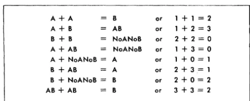
3A+A B or 1 + 1 = 2
A+B AB or 1+2=3
B + B NoANoB or 2+2=0
A + AB NoANoB or 1+3=0
A + NoANoB = A or 1+0=1
B + AB A or 2+3=1
B + NoANoB = B or 2+0=2
AB + AB B or 3+3=2
Figure 13. A-Bit and B-Bit Values
four. For example, a value of five is represented as a value of 1 (Figure 13).
Address modification to a higher address in the 000-999 address range is:
Increase address 472 by 345 472
+
345 = 817This is a normal add operation with no overflow in-volved.
Address modification to an address greater than looO is:
Increase address 912 by 314
912
+
314 = 1226 or 8 268 = A2 (overflow in high-order position sets an A-bit
using modulus 4 arithmetic and turns on the
arithmetic overflow indicator).
Increase address 1754 (X 54) by 1204 (804)
1754
+
1204 = 2958 X54+
804 = R58 X = (A7)8 = (A2)
Using the fUles of modulus 4 arithmetic, A
+
A = B-bit, the new address is:958 with a B-bit over the high-order position (B9
=
R)or R58 (2958).
To decrease an address, a different means must be used. Modulus 4 arithmetic operates for addition only. Decreasing an address requires the addition of a com-plement, rather than doing a conventional subtract operation.
In systems equipped with 4,000 core-storage posi-tions, the 16,000's complement of the decrement figure is added to the address to be modified (modulus 16 arithmetic).
Decrease address 879 by 148 879 - 148 = 731
4th 1,000-block of a 4,000-block
~
!
!
f
4th 4,000-block//
16,000 - 148
=
15,852 (852 or H5B)16,000's complement of 148
FIELD B
879
B B
A A
\ I
FIELD A
B B
A A
\ I
852852
_---1
B A
/
731 Result after overflow (arithmetic overflow indicator set ON)
The add operation is performed as shown. The A-field figure is added to the B-field figure. The digital result is 731 and the arithmetic overflow indicator is set ON. Because an add operation has taken place, the units position ends up with a plus sign (an A- and a B-bit). The arithmetic overflow in the hundreds posi-tion adds an A-bit to the A- and B-bits already there, resulting in a zone-bit configuration of no A- and no B-bit (see Figure 13). The A-bit addition increases the zone-bit value to 16. A value of 16, according to modu-lus 16 rules, has a new address value of 0 (000-999 core-storage address block). This means that 731 is the actual address.
Modulus 4 arithmetic is normally used in 1440 systems that contain only 4,000 core-storage positions. With care, this address modification method could be used on systems with more core-storage capacity, but its usefulness is negligible because 1440 systems with more than 4,000 core-storage positions are equipped with the MODIFY ADDRESS instruction.
Modify Address Instruction Method
[image:16.621.48.294.66.166.2]Modify Address (Two Addresses)
Instruction Format.
Mnemonic
MA
Op Code
#
A-address
xxx
B-address
xxx
Function. This instruction causes the 3-character field,
specified by the A-address (A-field), to be add~d to the 3-character field specified by the B-address (B-field). The result is stored in the B-field. The three numerical portions and the zones of the units and hundreds positions of the B-field make up the 3-character result. For example:
3-Character Actual
Location Contents Address Address
A-address A-field 100 100
B-address B-field L2F 14326
B-field M2F 14426
Word Marks. Word marks are not affected, and are
not required to define the A- or B-fields.
If
word marks are present, they are ignored and remain un-changed in both fields.Timing. T = .0111 (Lr
+
9) ms.Note: Rules for the addition of zone bits are the same as in modulus 4 arithmetic, with one addition. This instruction makes it possible to reflect the hundreds position zone-bit overflow in the units position when the address is modified to a higher 4,000-block of core storage. When a zone-bit overflow occurs during the hundreds position modification, an additional cycle is executed to adjust the units position zone-bit configuration.
Address Registers After Operation.
I-Add. Reg. A-Add. Reg. B-Add. Reg.
NSI A-3 B-1 or B-3
Example. Add the 3-character address labeled ADDA
(0985) to the 3-character address labeled ADDB (1313), Figure 14.
Autocoder
I'
lobelOPERAND
:~
~
.
:
Assembled Instruction: # 985 T13
Figure 14. Modify Address (Two-Addresses)
Modify Address (One Address)
Instruction Format.
Mnemonic
MA
Op Code
#
A-address
xxx
Function. This format of the MODIFY ADDRESS instruc-tion causes the 3-character field, specified by the A-address, to be added to itself. The result is stored in the A-field.
Word Nlarks. Word marks are not required to define
the A-field. If they are present, they are ignored and remain undisturbed in the A-field.
Timing. T
=
.0111 (Lr+
9) ms.Address Registers After Operation.
I-Add. Reg. A-Add. Reg. B-Add. Reg.
NSI A-3 A-lor A-3
Example. Double the address labeled ADDC (2956),
and store the result at ADDC (Figure 15).
Autocoder
I.. lobel ~perati~ OPERAND
t==!~:=~'5~M~A~J~~'~b~=C::s==~~o==~~O~=~4:0==~:~==~~
Assembled Instruction: # R56Figure 15. Modify Address (One-Address)
Indexing Method
Any 1440 system can modify addresses by installing the indexing and store address register special feature. A complete description of this feature can be found in Special Features, Form A26-5669.
System Operations
The operations performed by an IBM 1440 Data
Proc-essing System can be arranged into these general classifications:
I. Arithmetic operations 2. Logic operations 3. Data-moving operations 4. Miscellaneous operations 5. Edit operation
6. IBM 1447 Console operations
Arithmetic Operations
The IBM 1440 Data Processing System adds and
sub-tracts, by applying the add-to-storage method of op-eration. The two factors to be combined are added within core storage without the use of special accumu-lators or counters. Because any storage area can be used as an accumulator field, the capacity for perform-ing arithmetic functions is not limited by standard-size accumulators or by a predetermined number of accum-ulators within the system. In arithmetic operations, the 1440 system considers blanks and zeros the same. An unsigned field is considered positive by the system.
All arithmetic functions are performed under com-plete algebraic sign control. The sign of a factor is determined by the combination of zone bits in the units position of the fields specified by the instruction being executed.
Figure 16 shows the four possible combinations of zone bits and the values of the signs they represent. The standard machine method of signing a field is to indicate a positive factor with A- and B-bits (12-zone), and to indicate a negative factor with a B-bit (II-zone).
The arithmetic operations in the IBM 1440 Data
Processing System are performed by using one of two
SIGN
Plus Plus Minus Plus
BCD CODE BIT CONFIGURATION
No A· or B·Bit A· and B·Bits B·Bit Only A·Bit Only
Figure 16. Sign Bit Equivalents
CARD CODE CONFIGURATION
No Zone 12 Zone 11. Zone OZone
TYPE
A·FLD. B·FLD. TYPE OF ADD SIGN OF OF
SIGN SIGN CYCLE RESULT
OPER.
+
True Add ++
A - Comp/. Add Sign of Greater
0+
0 + Comp/. Add Value
-- True Add
-S - True Add
-U +
--
f-----"-~.--B + Comp/. Add Sign of Greater
T - .••.... _-_ ..
-R
-Comp/. Add Value A - -_ .... - _ .. _.- -~---~.-""-"---
---~.----.--C +
T True Add +
~-Figure 17. Types of Add Cycles and Sign of Result for Add and Subtract Operations
types of add cycles incorporated in the system. The two types of add cycl~s are:
1. true add
2. complement add
The type of add cycle performed depends on the arithmetic operation and the signs and values of the two factors involved (Figure 17).
True Add
A true-add cycle is specified when the total number of minus signs is an even number (0 or 2). The signs con-sidered are the signs of the factors and the sign of the operation.
The sign of the result after a true-add cycle carries the original sign of the B-field when either an add or a subtract operation is performed (Figure 18).
Complement Add
[image:18.615.312.530.130.319.2] [image:18.615.55.275.625.709.2](+
B)+
(--I-A)=
+
RFIELD B FIELD A
0065
+
0017+
~~.~---~I
Result 0082
+
(- B)
+ (-
A) = - RFIELD B FIELD A
0016 -
0009-0009~.~---~1 Result 00'2'5
-(- B) - (+A) = - R
FIELD B FIELD A
0025 - 0011
+
~~.~---~I
Result
0036-(--I-B) - (-A) = --I-R
FIELD B FIELD A
0036
+
0062-~~.~---~I
Result 0098
+
Figure 18. True-Add Cycle Examples
(- B) + (+A) = ± R
FIELD B FIELD A
0036 - 0017
+
9982 -+--9982 _ _ _ --'I
Initial Carry Result 9019 - Carry
(Recomplementing Unnecessary)
(+B)
+
(-A)=
± RFIELD B FIELD A
0055
+
0034-9965 ~ 9965 - - - - . I I
Result
po2l
+
Initial Carry Carry
(Recomplementing Unnecessary)
(+ B) - (+A)
=
± RFIELD B FIELD A
0085
+
0073+
9926 ~ 9926 ---'I
1 Initial Carry Result 00IT I
+
Carry(Recomplementing Unnecessary)
( - B) - (-A)
=
± RFIELD B FIELD A
0078 -
0056-9943 -+--9943 - - - -.... 1
Result 0022 -I
Initial Carry Carry
(Recomplementing Unnecessary)
Figure 19. Complement-Add Cycle Examples
B-field. The presence of a carry indicates that the result in the B-field is a true figure (Figure 19). The original sign of the B-field is the sign of the result.
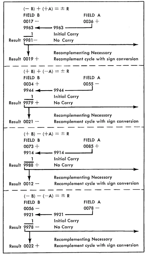
If there was no carry from the high-order position of the B-field, the result in the B-field is not a true figure. A recomplement cycle is performed to convert the result to a true figure. In an add operation that results in a negative figure, the sign of the result is always changed during a recomplement cycle, (Figure 20). The system generates the new sign automatically. A positive factor is indicated by the presence of an A-and B-bit over the units position of the factor. After a complement-add cycle, the sign of the result carries the sign of the greater value factor.
( - B) + (+A)
=
± RFIELD B FiElD A
0017 - 0036
+
9963 ~ 9963 - - - -.... 1
___ 1 Initial Carry Result 9981- No Carry
~'~l---Re-c-o-m-p-Ie-m-e-n-ti-n-g-N-e-Ce-s-s-ar-y---~~
Result 0019
+
Recomplement cycle with sign conversion(+
B)+
(-A)=
± RFIELD B FIELD A
0034
+
0055-9944 ~ 9944 - - - -.... 1 1
Result
9979 +
'l
Result 0021
-Initial Carry No Carry
Recomplementing Necessary
Recomplement cycle with sign conversion
(+ B) - (+A) = ± R
FiElD B FIELD A
0073
+
0085+
9914...-9914---.. 1
Result
ma
+
't
Result 0012
-Initial Carry No Carry
Recomplementing Necessary
Recomplement cycle with sign conversion
( - B) - (-A)
=
± RFIELD B FIELD A
0056 -
0078-9921 ~ 9921 ----~I
1 Initial Carry Result 9978 - No Carry
'l
Result 0022
+
Recomplementing Necessary
Recomplement cycle with sign conversion
[image:19.612.63.558.53.706.2] [image:19.612.326.559.286.693.2]Arithmetic Instructions
Add (Two Fields)
Instruction Format.
Mnemonic
A
Op Code
A
A-address B-address
xxx xxx
Function. The data in the A-field is added
algebrai-cally to the data in the B-field. The result is stored in the B-field.
Word Marks. The B-field must have a defining word
mark, because it is this word mark that actually stops the add operation.
The A-field must have a word mark, only if it is shorter than the B-field. In this case, the transmis-sion of data from the A-field stops after the A-field word mark is sensed. Zeros are then inserted in the A-register until the B-field word mark is sensed.
If the A-field is longer than the B-neld, the high-order positions of the A-field that exceed the limits imposed by the B-field word mark are not processed. For overflow conditions and considerations, assume that the A-field is the same length as the B-field.
(See Address ~lodification.)
Timing.
1. If the operation does not require a recomplement
cycle:
T = .0111 (LI
+
I+
LA+
LB ) ms.2. If a recomplement cycle is taken: T = .0111 (LI
+
I+
LA+
3 LB ) ms.If the multiply-divide special feature is installed, the 1440 timing for a recomplement cycle is:
T = .0111 (LI
+
1+
LA+
2 LB ) ms.Notes.
1 Sign control (see Figure 17):
If a recomplement cycle is taken, the sign of the B- (result) field is changed and the result is stored in true form.
2. Zone hits:
If the fields to be added contain zone bits in other than the high-order position of the B-field and the sign positions of both fields, only the digits are used in a true-add operation. B-field zone bits are removed except for the units and high-order positions in a true-add operation. If a complement add takes place, zone bits are removed from all but the units positions of the B-field.
3. Overflow indication:
If an overflow occurs during a true-add operation, the overflow indicator is set ON, and the overflow indications are stored over the high-order digit of the B-field. When the A-field exceeds, or is equal to, the B-A-field length, and the A-A-field
position that corresponds to the high-order B-field position contains a zone bit, this zone bit is added to any zone bits present in the high-order B-field position.
Condition Result
First overflow A-bit Second overflow
Third overflow Fourth overflow
B-bit A- and B-bits No A- or B-bits
For subsequent overflows repeat conditions 1 through 4. Overflow indication does not occur for a I-position field. The BRANCH IF ARITHMETIC OVERFLOW INDICATOH ON, B (III) Z, instruction tests and turns off the overflow indicator, and branches to an instruction or group of instructions if an overflow condition occurred. There is only one overflow indicator in the system. It is turned off either by executing a BRANCH IF ARITHMETIC OVERFLOW INDICATOR ON instruc-tion or pressing the start reset key on the 1447 operator panel.
Overflow indication does not occur for a I-position field.
Address Registers After Operation.
I-Add. Reg. A-Add. Reg. B-Add. Reg.
NSI A-Lw B-LB
Example. Add CURERN (0506) to YTDGRO (0708),
Figure 21.
Autocoder
L
label .~rati~ OPERANDI"-r<-_=====. =:
==~'~:'
:===::rc:C=-,.,,'U:R.:E.~~~N.:;,:Y=!T~~""'"",G:£:Q:~~:!!!==-!----'4"'-O._=~
Assembled Instruction: A 506 708Figure 21. Add (Two Fields)
Add (One Field)
Instruction Format.
Mnemonic
A
Op Code
A
A-address
xxx
Function. This format of the ADD instruction causes
the data in the A-field to be added to itself.
Word Marks. The A-field must have a defining word
mark. It is this word mark that stops the add opera-tion. This instruction must be followed by a word mark in the position after the A-address.
Timing. T
=
.0111 (LI+
1+
2 LA) ms.Address Registers After Operation.
I-Add. Reg. A-Add. Reg. B-Add. Reg.
Example. Add to itself the data at EXEMPT (0981),
Figure 22.
Autocoder
~
labelI:
Assembled Instruction: A 981 Figure 22. Add (One Field)
Subtract (Two Fields)
Instruction Format. Mnemonic
S
Op Code
S
A-address
xxx
OPERAND
~. I :
B-address
xxx
Function. The numerical data in the A-field is
sub-tracted algebraically from the numerical data in the B-field. The result is stored in the B-fleld. Refer to Figure 17 for the sign that results from a specific subtract operation.
Word Marks. A word mark is required to define the
B-field. An A-field requires a word mark, only if it is shorter than the B-field. In this case, the A-field word mark stops transmission of data from the A-field.
Timing.
1. If the operation does not require a recomplement
cycle:
T = .0111 (LI
+
1+
LA+
LB ) ms. 2. Subtract - recomplement cycle necessary:T = .0111 (LI
+
1+
LA+
3Ln) ms.H the multiply-divide special feature is installed, the 1440 timing for a recomplement cycle is:
T = .0111 (LI
+
1+
LA+
2LB ) ms.Note. If a recomplement cycle is taken, the sign of the
B-(result) field is changed, and the result is stored in true form.
Address Registers After Operation.
I-Add. Reg. A-Add. Reg. B-Add. Reg.
NSI A-Lw B-Lw
Example. Subtract CUFICA (00753) from CURGRO
(0896), Figure 23.
Autocoder
OPERAND
:~
I~
~ label
L .:
Assembled Instruction:! 753 896
Figure 23. Subtract (Two Fields)
Subtract (One Field)
Instruction Format. Mnemonic
S
Op Code
S
A-address
xxx
Function. The data at the A-address is subtracted from
itself. If the A-field sign is mihus, the result is a minus zero. If the A-field sign is plus, the result is a plus zero.
Word Marks. The A-field must have a defining word
mark. This instruction must be followed by a word mark in the position after the A-address.
Timing. T = .0111 (LI
+
1+
2LA) ms.Address Registers After Operation.
I-Add. Reg. A-Add. Reg. B-Add. Reg.
NSI A-LA A-LA
Example. Subtract from itself the field labeled LIMIT
(units position is 0395), Figure 24.
Autocoder
t;
labelAssembled Instruction:! 395
Figure 24. Subtract (One Field)
Zero and Add (Two Fields)
Instruction Format. Mnemonic
ZA
Op Code
?
A-address
xxx
B-addres$
xxx
Function. This instruction functionally adds the A-field
to a zeroed B-field. Technically, this is accomplished
positions of the B-field are set to zero if the B-field is larger than the A-field. The data from the A-field moves directly from the A-register to storage. Zone bits are stripped from all positions except the units position. Blanks in the A-field are stored as blanks the B-field.
Word Marks. A word mark is required for definition of the B-field. It is required in the A-field, only if
it is shorter than the B-field. If the A-field is shorter than the B-field, all extra high-order B-field posi-tions contain zeros. But the transmission of data from A stops when the A-field word mark is detected.
Timing. T = .0111 (Lr
+
1+
LA+
LB ) ms.Note. The sign of the result always has both A- and B-bits if it is positive. If the sign is negative, it has only a B-bit.
Address Registers After Operation.
I-Add. Reg. A-Add. Reg. B-Add. Reg.
NSI A-Lw B-LB
Example. Zero WHTAX area (0796-0802) and add new TAX (0749-0754) to WHTAX (Figure 25).
Autocoder
OPERAND
..
10~I. • ~
Assembled Instruction: 1 754 802
Figure 25. Zero and Add (Two Fields)
Zero and Add (One Field)
Instruction Format. Mnemonic
ZA
Op Code ?
A-address xxx
Function. This format of the ZERO AND ADD instruction is used to strip the A-field of all zone bits, except in the units (sign) position. The A-field sign is retained.
If the field plus sign bit configuration is not an A-and B-bit, it is changed to the A- A-and B-bit con-figuration.
Word Marks. The A-field must have a word mark in its high-order position.
Timing. T = .0111 (LI
+
1+
2LA ) ms.Address Registers After Operation.
I-Add. Reg. A-Add. Reg. B-Add. Reg.
NSI A-LA A-LA
Example. Strip zone bits from TOTAL (0560) area (Figure 26).
Autocoder
Assembled Instruction: 1 560 Figure 26. Zero and Add (One Field)