2016 6th International Conference on Information Technology for Manufacturing Systems (ITMS 2016) ISBN: 978-1-60595-353-3
1 INSTRUCTION
Sensor is as a kind of test equipment, which can forecast information and use a certain rule to output electrical signals or other information, so as to meet the requirements of information transmission, processing, storage, display, record and control and so on. With sensing technology developed rapidly in recent years, the study of new theory, new materials and new technology in sensors is more thoroughly and widely. New varieties, new structures, new applications sensors are constantly emerging. Magnetically controlled shape memory alloy (MSMA) is kinds of alloy materials with reversible characteristics, which typical representative is Ni2MnGa [1]. Based on the research of MSMA
inverse characteristics, high strain features and high response frequency of this material can be fully displayed.
The previous model of MSMA sensor consists of four parts: core, exciting coil, detecting coils, pre-pressure systems [2, 5]. In this paper, the sensor structure has partly optimized. The output voltage of the sensor is analyzed when removing the pre-pressure systems. The rationality and correctness of the sensor structure are verified by experiments. On the basis of experimental data, the mathematical model of the sensor without pre-pressure is derived by the parameter identification algorithm, and comparison experimental data and calculated value, the correctness, feasibility of the model and the parameter identification algorithm are proved.
2 SENSOR STRUCTURE
The structure of MSMA sensor is shown in Figure 1. The research is done to optimize the sensor pre-load pressure systems. Recovering MSMA element deformation can be achieved by spring provides a pre-pressure. At the same time, the spring will make the output displacement of the exciter decreasing, so as the induction voltage of the sensor is reduced .In addition, when exciter provides high frequency external force; it cannot play a role in restoring the deformation of MSMA element because it is restricted by the inherent frequency of the spring. In order to overcome these adverse effects and obtain higher induced voltage, the force that spring exerts to material should be removed so that the exciting force is applied to the material directly.
The MSMA material size of 2.5mm×5 mm×20mm is used in this experiment. Permanent magnet and excitation coil can provide required magnetic field for the sensor. Changing the current can control the magnetic field of the excitation coil. Exciting force is applied on the material through movable rod and make the material has a certain deformation, so that sensor’s magnetic flux is changed. Hall sensor measures the magnetic field in the air gap of the core, eddy sensor detects the displacement of MSMA element, and force sensor measures the exciting force.
Study on the Model Parameter Algorithm of the MSMA Sensor
Jun
Lu, Lin Gao, Qingyang Yu, Litian Wu
School of Automation and Electrical Engineering, Shenyang Ligong University, Shenyang, Liaoning, China
Figure 1. MSMA sensor structure.
[image:2.612.363.511.141.412.2]Induced voltage of structure optimization before and after is shown in Figure 2. It can be seen from the Figure 2, inducted output voltage of optimized sensor increased significantly. Therefore, experimental results verify the feasibility of the sensor partly optimized structure.
Figure 2. Comparison chart of induced voltage.
3 PARAMETER IDENTIFICATION
3.1Chaos particle swarm optimization
Particle swarm optimization (PSO) is a kind of swarm intelligence optimization algorithm, which is proposed by Kennedy and Eberhart in 1995[6]. PSO
algorithm simulates the flying behavior of birds to find food [7]. Generally, randomness motion state is obtained by deterministic equations called Chaos. A variable, which is presents a chaotic state, is called chaotic variable. Chaos optimization algorithm searches the global optimal value by using the chaos variable, without considering the continuity and the differentiable of the optimization problems [8, 9]. In the optimization process, chaos in full accordance with the law of chaotic motion to search. Therefore, it has a greater probability that obtain the optimal solution by using chaos optimization algorithm. The
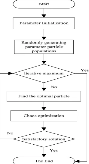
chaotic variables have the characteristics of ergodicity, randomness and regularity. The ergodicity of the chaotic variable is mainly used in this study. Chaotic particle swarm optimization algorithm searches optimum position and generates chaotic sequence based on Chaos variables. The flow chart of chaos particle swarm optimization is shown in Figure 3.
Figure 3. The flow chart of chaos particle optimization algorithm.
3.2 Mathematical model
Neglect the effect of magnetic saturation, hysteresis and eddy current effecting on the magnetic circuit of MSMA sensor. The model of the sensor composed of the exciting coil, permanent magnet and core [10]. Magnetic circuit model [11] of MSMA sensor is shown in Figure 4.
Figure 4. Magnetic circuit model of MSMA sensor.
In the equivalent magnetic circuit model, ФP is
[image:2.612.71.280.339.492.2] [image:2.612.319.551.541.677.2]produced by the permanent magnet and the exciting coil; ФM is the magnetic flux through MSMA
element; ε is the deformation of MSMA element; RmM(ε) is magnetic reluctance after MSMA element
deformation; RmG(ε) is the air gap reluctance value;
Rmσ is magnetic flux leakage reluctance value
through the MSMA element; RmS is internal
reluctance value of the excitation coil .magnetic flux of the induction coil ФM is:
(1)
It can be represented by the general formula: (2)
The coefficients of α, β, γ will be recognized in
(2); BM is the bias magnetic field of MSMA sensor, which is offered by the permanent magnet and the exciting coil.
According to the deformation of MSMA element and the curves of stress and strain, MSMA element stress-strain relationship is linear. The expression can be written as:
(3) Which k and h are uncertain parameters, σ is
pressure that exciter provides。
As the sensor input, the exciter makes the material deformation. The exciting force F is:
(4)
The expression of force and stress can also be written as followed:
(5)
SMSMA is the cross-sectional area of the MSMA
material.
The induction voltage differential equation is:
(6)
Where (3), (4) and (5) are brought into (6), the relationship between the induction voltage and the other parameters can be obtained:
(7)
[image:3.612.322.546.114.184.2]According to the chaotic particle swarm optimization algorithm, each parameter value is shown in Table 1 by chaotic particle swarm optimization algorithm parameter identification.
Table 1. Parameter value by CPSO parameter identification.
parameter value parameter value
k1 13906.48 k4 6424.11
k2 216.32 k5 407.15
k3 146.66
The parameters after identification are brought to (7). The induced voltage Ue without pre-pressure is:
2
13906.48 cos
407.15 216.32
146.66 64 sin
24.1
( 1)
M m
e
m
MSMA M
MSMA
B F t
U N F t S B S ω ω
ω
⋅ ⋅ ⋅ − − + − ⋅ − = (8)Coefficients used in CPSO parameter identification are as follows: individual learning factor c1=2; social learning factor c2=2; particle
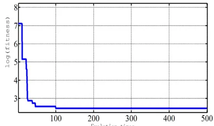
swarm scale is 100; iteration number is 500; chaotic optimization 200. Chaos particle swarm algorithm is used to identification five parameters. Classical logistic chaotic signal generator is used to generate chaotic sequence, return to the original solution space by inverse mapping, the adaptive value of the ergodic feasibility position on the chaotic variable is calculated by the fitness function. Figure 5 is the evolution curve of chaos particle swarm optimization algorithm with 5 controlling parameter. It can be seen from Figure 5 that the CPSO has obviously convergence effect, it can adapt to recognizing parameters on the experimental.
Figure 5. Evolutionary curve of chaos particle optimization algorithm.
4. EXPERIMENTAL VERIFICATION
The model can calculate the induced voltage value and get the changing waveform under the condition of different external conditions (biased magnetic field) and excitation force (amplitude and frequency). The optimum solution obtained by [ ( ) ( )]
( ) ( ) S mS
M
mG mM m mS mC
mG mM m
R
R R R
R R
R R R
σ σ
ε
ε
ε
ε
Φ Φ = + + + + +M
B
Mε β
α
ε γ
+
Φ =
+
t FF = m sin
ω
M S M A
F =
σ
⋅SM M
e
d d d
U N N
d t d d t
ε ε Φ Φ = = ⋅ 1 5 2 2 3 4 cos sin ( ) M m e m MSMA M MSMA
k B F t
U N k
k F t
S k B k
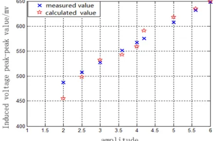
[image:3.612.324.544.489.619.2]chaotic particle swarm optimization algorithm and measured value are shown in Figure 6. It can see that the error between the optimal solution and the experimental data is smaller, and the average error of the calculated output is 2.5%.
Figure 6. Comparison calculated value and measured value.
Comparison calculated value with (5) and experimental data under the same experimental condition, when the frequency, biased magnetic field and amplitude changes separately, the results are shown in Figure 7, 8, 9 respectively.
Figure 7. Comparison calculated value and the experimental data when Frequency changes.
Figure 8. Comparison calculated value and experiment data when biased magnetic field changes.
Figure 9. Comparison calculated value and experimental data when amplitude changes when amplitude changes.
The error between experimental and calculated value is in an acceptable range. In the same experimental condition, when the three variables of frequency, biased magnetic field and amplitude variation simultaneously, the result is shown in Figure 10, the calculated values have better agreement with the experimental data.
Figure 10. Comparison calculated value and experiment data when biased magnetic field, frequency and amplitude change simultaneously.
4. CONCLUSION
[image:4.612.63.292.112.267.2] [image:4.612.318.541.333.456.2] [image:4.612.56.278.367.521.2] [image:4.612.58.279.557.712.2]5. ACKNOWLEDGMENT
The research work reported in this paper is supported by the National Nature Science Foundation of China under the fund of 51377110.
REFERENCES
[1]Ullakko K, J HuangK, Kantner C, Kantner, et al. 1996. Large Magnetic-field-induced Strains in Ni2MnGa Single Crystals. Appl Phys Lett, 69 (13): 1966-1968.
[2]Lu Jun, Li Min, Wang Fengxiang. 2014. Theoretical and experimental vibration sensor based on MSMA inverse characteristics. Transactions of china electro-technical society. 29(5):233-238.
[3]Lu Jun, Yang Kuan, Wang Fengxiang. 2013. Model and experiment characteristic on vibration sensor of magnetically controlled shape memory alloy. Electric Machines and Control, 18 (3): 20-24.
[4]Lu Jun, Li Xia, Wang Zhongma. 2015. Signal Process and Fault Detection of MSMA Vibration Sensor Based on
Wavelet Analysis. Transactions of china electro-technical society. 30(10): 354-360.
[5]Wang Fengxiang, Li Wenjun, Zhang Qingxin, Wu Xinjie, Li Chenxi. 2005. Study on a differential actuator if magnetically controlled shape memory ally. Proceedings of the CSEE. 25(18): 135-139.
[6]Eberhart R. Kennedy J. 1995. A new optimizer using partial swarm theory .Proof of the sixth international conference on Micro Machine and Human Science, Nagoya, Japan.39~43.
[7]Kennedy J, Eberhart R C. 1995. Particle swarm optimization. Proof the First IEEE International Conference on Neural Networks. 1942-1948.
[8]Gao Fei, Tong Hengqing. 2006. Parameter estimation for chaotic system based on particle swarm optimization [J].ACTA PHYSICA SINICA. 55(2):577-582.
[9]Gao Ying, Xie Sheng Li. 2004. Chaos Particle Swarm Optimization Algorithm. Computer Sciences. 31(8): 13-15.
[10]Peng Zhiming, Jin Xuejun, Xu Zuyao.2004. Research progress of Ni2MnGa magnetic field induced shape memory alloys. Functional Materials. 35 (02): 135-138.