University of Huddersfield Repository
Charitopoulos, Romanos and Sibley, Martin J.N.
Experimental coder/decoder of dicode pulse position modulation.
Original Citation
Charitopoulos, Romanos and Sibley, Martin J.N. (2009) Experimental coder/decoder of dicode
pulse position modulation. In: Proceedings of Computing and Engineering Annual Researchers'
Conference 2009: CEARC’09. University of Huddersfield, Huddersfield, pp. 124129. ISBN
9781862180857
This version is available at http://eprints.hud.ac.uk/id/eprint/6877/
The University Repository is a digital collection of the research output of the
University, available on Open Access. Copyright and Moral Rights for the items
on this site are retained by the individual author and/or other copyright owners.
Users may access full items free of charge; copies of full text items generally
can be reproduced, displayed or performed and given to third parties in any
format or medium for personal research or study, educational or notforprofit
purposes without prior permission or charge, provided:
•
The authors, title and full bibliographic details is credited in any copy;
•
A hyperlink and/or URL is included for the original metadata page; and
•
The content is not changed in any way.
For more information, including our policy and submission procedure, please
contact the Repository Team at: [email protected].
EXPERIMENTAL CODER/DECODER OF DICODE PULSE POSITION
MODULATION
R. A. Charitopoulos, M. J. N. Sibley
University of Huddersfield, Queensgate, Huddersfield HD1 3DH, UK
ABSTRACT
Dicode Pulse Position Modulation has been proposed as an alternative coding scheme which has many advantages over previous Pulse Position Modulation formats. As it is a new coding scheme, few analyses and less experimental results have been published. For the first time, the original design of an experimental Dicode Pulse Position Modulation coder and decoder and experimental results are presented in this paper. These circuits are the basic tools needed for any further investigation of this format.
Keywords: Coder, Decoder, Dicode Pulse Position Modulation (DiPPM)
INTRODUCTION
Many Pulse Position Modulation (PPM) formats have been investigated in the past such as Multiple Pulse Position Modulation (MPPM) [1-2], Differential Pulse Position Modulation (DPPM) [3-4] and many related modulation coding schemes such as Pulse Interval Modulation (PIM) [5], Digital Pulse Interval Modulation (DPIM) [6] and Dual Header Pulse Interval Modulation (DH-PIM) [7]. Analysis has shown that although each code has many advantages compared to Pulse Code Modulation (PCM), it does so at the expense of bandwidth. This makes them attractive for use in glass fibre or directed line of sight networks where bandwidth is not at a premium. Unfortunately glass optical fibre cable is expensive and is not suitable for everyday use such as networks. On the other hand, Plastic Optical Fibre (POF) is inexpensive but suffers with a low bandwidth making it unattractive for use with PPM schemes.
Digital PPM (DigPPM) had been proposed in the past [8-11] as the best coding scheme for optical communication, compared to the other PPM formats. Unfortunately the format of digital PPM means that although the scheme offers a sensitivity advantage over standard PCM, it does so at the expense of a large bandwidth expansion factor resulting in a final data rate that can be prohibitively high. This led to the investigation of various other PPM schemes. One of those was Dicode PPM – ISI guards, which was proposed by M.J.N. Sibley [12] as a more advantageous format than DigPPM. More theoretical analysis has been followed on Dicode PPM scheme by the same author [12-15].
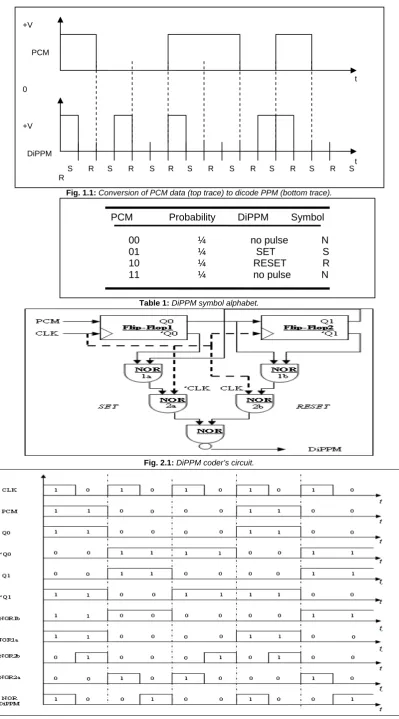
In 2006, R.A. Cryan and M.J.N. Sibley [16] presented Dicode PPM (DiPPM) in a different form. They considered reducing the impact of intersymbol interference on dicode PPM by proposing an alternative detection strategy to the slope detection technique normally employed in PCM systems. By moving from slope detection to central decision detection, they showed that the DiPPM receiver can be significantly simplified with equivalent sensitivity performance in the higher fibre bandwidths and considerably enhanced performance at the lower bandwidths. Hence, DiPPM at its final version, is very easy to implement as it uses two slots to transmit one bit of PCM and, unlike DigPPM, the DiPPM system achieves a better sensitivity than PCM at a slot rate of twice the original PCM data rate [12-16]. The data is coded as follows: a PCM transition from zero to one produces a pulse in slot S and a one to zero transition generates a pulse in slot R (fig. 1.1). No pulses are transmitted when the PCM data is constant at either 1 or 0.
Table 1 shows the dicode PPM symbol alphabet. As the symbols are four, each symbol has a probability of ¼. However, the probability of a no pulse sequence (N) is ½ as it occurs with both 00 and 11 PCM sequence. The S symbol has the same probability as the no pulse (N), because there are only two possible PCM sequences (00 or 01) after an R pulse has been transmitted. A typical dicode PPM sequence would be S, xN, R with probability of ¼,
(
1
/
2
)
x and ½ respectively.results [20-23]. For the first time the hardware DiPPM coder and decoder will be presented and analysed in this paper, which are the basic investigation tools of the DiPPM scheme.
DiPPM CODER/DECODER
As no version of the DiPPM coder and decoder construction has been reported in the past, these two parts had to be implemented to allow for further investigation of DiPPM scheme,. As the bit rate of the data to be coded was at a high frequency (100 -120 Mbit/s) [20-23], logic components from the F100K ECL family were used.
2.1 DiPPM Coder
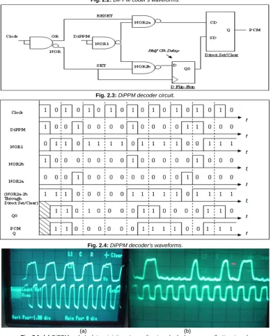
The DiPPM coder is the part of a DiPPM system that formats any PCM sequences into sequences that contain the DiPPM alphabet symbols (Table 1). The logic components that have been used to complete this DiPPM coder are two Flip-Flops and five NOR gates (figure 2.1). Flip-Flop 1 and Flip-Flop 2 form a two bit store, the outputs of which are used to produce the SET and RESET sequences.’Q0 and Q1 are passed through a NOR gate (1a) to produce the SET sequence and the pair Q0 and ‘Q1 produce the RESET sequence through the NOR gate (1b). The use of the CLK and the NOT CLK signal is necessary to retime the DiPPM SET and RESET sequences. The DiPPM SET and RESET sequences are produced by the two NOR gates (2a and 2b). A NOR gate combines these two sequences and produces the final DiPPM sequence
2.2 DiPPM Decoder
The DiPPM decoder converts the DiPPM coded signal back to PCM format. The DiPPM decoder’s parts are a NOR/OR gate, three NOR gates, a D Flip-Flop and a Direct Set/Clear component as figure 2.3 shows. In common with the DiPPM coder, the clock and NOT clock signal have to be used. These were generated by passing the clock signal through a NOR/OR gate. The DiPPM input signal to the decoder was inverted by a NOR gate prior to being gated with the clock and Not clock to produce the SET and the RESET sequence independent from the other one. The Direct SET/Clear component is the component that will produce the PCM signal by giving a high amplitude when the sequence SET is one, and zeros when the RESET sequence is 1. But even when the SET and RESET sequence are independent, it can be seen by figure 2.4 that they are not producing the correct decoding. Thus, a half clock period delay has to be introduced with the use of a D-type Flip-Flop. A synchronisation fault exists in the DiPPM decoder because the SET signal passes through one more component than the RESET signal, before both reach the Direct Set/Clear component.Thus, a delay has been added from the D Flip-Flop component at the SET sequence.
DISCUSSION
3.1 Measurements from the DiPPM Coder
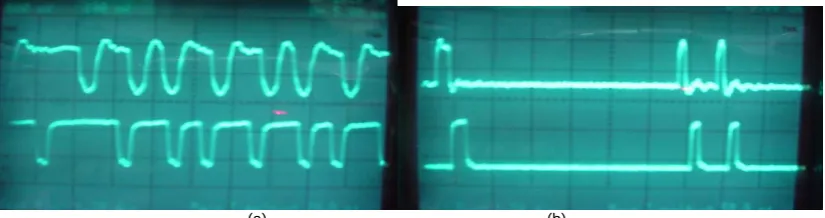
Running the system with a deterministic PCM input (1, 0, 1, 0, 1…) the output DiPPM sequence is shown at figure 3.1a in comparison with clock sequence. The DiPPM deterministic sequence has been perfectly synchronised with the clock. Figure 3.1a clearly shows that the DiPPM SET (10) gives a bit (1) at the beginning of a period clock and the DiPPM RESET (01) gives its bit (1) at the half of the clock period as expected (Table 1.A). Taking the same measurements as previous, but with Pseudo-random Binary Sequence (PRBS) PCM input signal to the DiPPM coder, the outcome sequence of the last is as shown in figure 3.1b.
3.2 Measurements and confirmation of DiPPM Decoder
The output of the DiPPM decoder, when its input signals are a deterministic DiPPM and the clock, is given in the figure 3.2a.
The PCM formatted output of the DiPPM decoder is perfectly synchronised with the clock. As was expected the start edge of every pulse starts when the clock period starts. Figure 3.2(b) shows the DiPPM PRBS input of the decoder compared with the DiPPM decoder’s output. From the comparison of the waveforms it can be seen that the DiPPM sequence has been decoded correctly back to the PCM form. The delay that appears between those two sequences is a result of the delay in the decoder.
CONCLUSIONS
In this paper, the construction of a DiPPM coder and decoder has been presented for the first time. Theoretical representations of DiPPM coder and decoder waveforms and practical outputs have been given. The two most basic parts of the DiPPM system, coder and decoder, have been developed and further investigation on DiPPM scheme can be achieved with the use of them.
REFERENCES
1. M.J.N. Sibley: ‘Analysis of multiple pulse position modulation when operating over graded-index plastic optical fibre’, Iee Proc.-Optoelectron., Vol. 151, No. 6, Dec. 2004
2. K. Nikolaidis M.J.N. Sibley: ‘Investigation of an optical multiple PPM link over a highly dispersive optical channel’, IET Optoelectron., 2007, 1, (3), pp. 113-119.
3. R.E. Peile: ‘Error correction, interleaving and differential pulse position modulation’, International Journal of Satelite Communications, vol. 6, no. 2, pp. 173-187, 1988.
4. Da-shan Shiu, Joseph M. Kahn:’ Differential pulse-position modulation for power-efficient optical communication’, IEEE Trans. On Comm, Vol.47, no. 8. August 1999.
5. S.D. Marougi, K.H. Sayhood: ‘Noise performance of pulse interval modulation systems’, International Journal of Electronics. Vol. 55, no. 4, pp 603-614, 1983.
6. ,Z. Ghassemlooy, A.R. Hayes and B. Wilson: ‘Reducing effects of intersympol interference in diffuse DPIM optical wireless communication’, IEE Proc-Optoelectron, Vol. 150, No. 5, October 2003.
7. N.M. Aldibbiat, Z. Ghassemlooy and R. Mclaughlin: ‘Dual header pulse interval modulation for dispersive indoor optical wireless communication systems’, IEE Proc. Circuits Devices Syst., 2002, 148, (3), pp.187-192.
8. Elmirghani, J.M.H., Cryan, R.A., Clayton, F.M.: ‘Spectral characterization and frame synchronisation of optical fibre digital PPM’, Electron. Letters, Vol. 28, No 16, 1992.
9. Garrett I.:’ Digital Pulse-position modulation for Transmission over Optical Fiber Channels with Direct and Heterodyne Detection’, IEEE Trans. Comm. Vol COM-31, pp.518-527, 1983.
10. N. Calvert: ‘Digital Pulse Position Modulation’, PH.D. Thesis, C.N.A.A., 1988
11. M.N. Calvert, M.J.N. Sibley, R.T. Unwin: ‘Experimental optical fibre digital pulse-position modulation system’, Electonics Letters, no. 24, pp. 129-131, 1988.
12. Sibley, M.J.N.: ‘’Dicode pulse-position modulation: a novel coding scheme for optical-fibre communications,’’ IEE Proc., Optoelectron., 2003,150, (2), pp. 125-131.
13. Sibley, M.J.N.: ‘’Suboptimal filtering in zero-guard, Dicode PPM system operating over dispersive optical channels,’’ IEE Proc., Optoelectron., 2004,151, (4), pp. 237-243.
14. Sibley, M.J.N.: ‘’Analysis of dicode pulse position modulation using a PINFET receiver and a slighty / highly dispersive optical channel,’’ IEE Proc., Optoelectron., 2003,150, (3), pp. 205-209.
15. M.J.N. Sibley: ‘Performance analysis of a dicode PPM system, operating over plastic optical fibre, using maximum likelihood sequence detection’, IEE Proc.-Optoelectron., Vol. 152, No. 6, December 2005.
16. R.A. Cryan and Sibley, M.J.N.: ‘’Minimising intersymbol interference in optical-fibre Dicode PPM systems,’’ IEE Proc., Optoelectron., 2006,153, (3), pp. 93-99.
17. R.A. Cryan: ‘Spectral characterisation of dicode PPPM Format’’, electronics letters, 3rd February 2005, Vol. 41, No. 3.
18. M. Menon and R.A. Cryan:’Optical Wireless Communications Utilizing a Dicode PPM Pin-BJT Receiver’ Microwave and optical techn. Letters/Vol. 45, No. 4, May 20 2005
19. I.H. Al-Suleimani, A.J. Phillips and M.S. Woolfson:’ Performance evaluation of optically preamplified dicode pulse position modulation receivers’, Eur.Trans. Telecom. 2008: 19:47-52, 25 May 2007. 20. Romanos Charitopoulos, M.J.N. Sibley: ‘Power Spectral Density of Dicode Pulse Position Modulation’,
School of computing and Engineering Researchers’ Conference, University of Huddersfield, Dec 2006. 21. R.A. Charitopoulos, M.J.N. Sibley: ‘Dicode Pulse Position Modulation Coder Simulation’, School of
computing and Engineering Researchers’ Conference, University of Huddersfield, Dec 2007.
22. R.A. Charitopoulos, M.J.N. Sibley: ‘Experimental Verification of the Power Spectral Density of Dicode PPM’, submitted for publication at IEE Proc.-Optoelectron.
Fig. 1.1: Conversion of PCM data (top trace) to dicode PPM (bottom trace).
Table 1: DiPPM symbol alphabet.
PCM Probability DiPPM Symbol
00 ¼ no pulse N 01 ¼ SET S 10 ¼ RESET R 11 ¼ no pulse N
S R S R S R S R S R S R S R S R
+V
PCM
0
+V
DiPPM
t
t
Fig. 2.2: DiPPM coder’s waveforms.
Fig. 2.3: DiPPM decoder circuit.
Fig. 2.4: DiPPM decoder’s waveforms.
(a) (b)
Fig. 3.1: (a) DiPPM coder’s deterministic outcome (top trace), clock sequence (bottom trace). (b) DiPPM coder’s PRBS outcome (top trace), clock sequence (bottom trace).
(a) (b)
(a) (b)
[image:7.595.94.507.73.182.2]