2017 2nd International Conference on Computer, Mechatronics and Electronic Engineering (CMEE 2017) ISBN: 978-1-60595-532-2
The Development of Winding Machine Capable of Winding
Special-shaped Coil Used for Electromagnetic Levitation Knitting
Xiu-sheng XU, Xiao-guang WU
*, Chi ZHANG, Bo YUAN and Xian-ze CUI
School of Mechanical Engineering and Automation, Wuhan Textile University, Wuhan, Hubei 430073, China
*Corresponding author
Keywords: Winding machine, Special-shaped coil, Motion control card, Interface program based on Windows platform.
Abstract. A miniature winding machine was designed and made for winding special-shaped coil used for driving knitting needle used in the test prototype of electromagnetic levitation circular knitting machine. The machine adopts USB1020-Altai independent four axis motion control card and 42 stepper motor as its hardware drive system, and at the same time, through the Qt Creator
interface program based on Windows platform as its control system. The using shows that the winding machine has the advantages of accurate wiring, high winding quality and wide application range. The main technical indexes, structure, working principle and control system of winding machine are introduced.
Introduction
With the successful application of electromagnetic levitation technology in train, more and more areas are exploring how to introduce the high-tech, maglev knitting technology is one of them, the so-called maglev knitting technology using electromagnetic force to drive the needle up and down movement to replace the traditional mechanical connecting rod drive.
On the one hand, the circular knitting machine needle in the upper and lower movement process of hooking yarn, yarn should not only be accurately hooked without any damage, but also needle need to cooperate with the sinker to complete circle action, only in this way can have good woven gauze consistent sparsity and smoothness of the needle, so need to maintain a stable and uniform in the upper and lower movement process of hooking yarn [1,2], through the stress analysis, it is easy to know that the electromagnetic coil of driving needle must be not common cylindrical shape, but irregular curve shape, by using Maxwell software analysis, the required shape of the coil can be obtained. On the other hand, most of the winding machines in the market are prone to uneven cable winding for micro wires [3](especially around the wires below 0.15mm).
In view of the above two problems, this paper developed a kind of winding machine for special-shaped and micro wire coil. It can wind different coil according to the inputting coil file and has the characteristics of high precision of winding displacement, more importantly, the coils made of it are arranged neatly and its outer surface is smooth.
Main Technical Performance
Table 1. Main working performance of winding machine. Applicable wire size 0.1-1mm
Applicable winding
length ≤90mm
Applicable coil diameter ≤50mm positioning accuracy 0.0025mm
Winding speed 1-5cycles per second
Rated voltage DC 24V
Rated power 100W
Structure and Working Principle
Structure
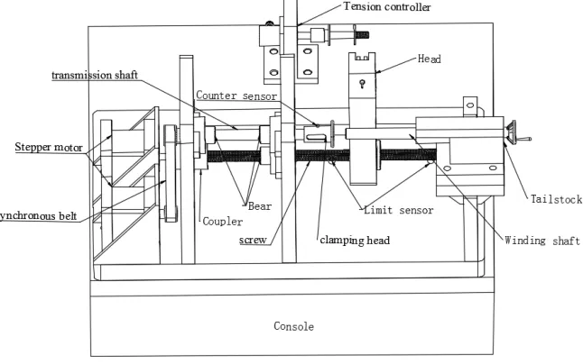
Generally speaking, the winding is realized by two actions, the kinking and winding displacement and its coordination action [4]. As shown in Figure 1 is the structural sketch of this miniature winding machine. The main working parts consists of winding displacement stepper motor, winding displacement screw, pendulum head, winding stepper motor, synchronous belt, transmission shaft, winding shaft, tailstock, coupler and bear, in addition, there are Tension controller, control display part and sensor feedback unit.
[image:2.612.146.469.465.667.2]The accuracy of the winding displacement is very important to the quality of winding, so the winding displacement screw is directly connected with the stepper motor through the coupler, thus avoiding the deviation caused by the transmission mechanism. The pendulum head that lead the wire is fixed with flange nut that compose screw-driven with winding displacement screw, so as to achieve the function of wire arranging. The winding stepper motor drive the transmission shaft by the connection of synchronous belt, and the transmission shaft drive the winding shaft by their D-shape fit, so as to achieve the function of wire kinking. Some sensors are arranged at the corresponding position of winding displacement screw to perform zero return and limit action, and a sensor is arranged on the clamping head part of the transmission shaft to count the turns.
Figure 1. Structure diagram of winding machine. Working Principle
so as to drive the pendulum head to a line diameter distance, the winding portion and the winding displacement portion are repeated at such a pace that the final coil can be got.
Before starting the work, first of all, the tension controller should be transferred to the corresponding tension state according to the type and thickness of the wire, which is crucial to a tight coil. Next, the winder returns to zero (the pendulum head goes back to its starting position), then insert the wire head through the pendulum head into the clamping head of transmission shaft, as shown in Figure 2, turn the tailstock to extend the winding shaft and press the wire head, last the machine can began to work. But before the formal start of the winding, the transmission shaft will automatically turn around a half of a circle, this is done to plug the wire into the slot and to eliminate the slack.
[image:3.612.171.437.238.365.2]Winding speed can be adjusted according to the type and thickness of wire. Generally speaking, the winding speed can be faster when the wire is thick, and it can be adjusted more slowly when it is thin.
Figure 2. Clamping head.
Control System
Hardware Control System
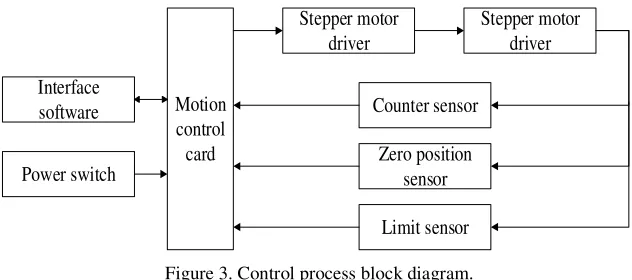
This machine adopts USB1020 Altai independent four axis motion control card and 42 stepper motor as its hardware drive system. The control process block diagram is shown in Figure 3.
Interface software
Power switch
Motion control card
Stepper motor driver
Stepper motor driver
Counter sensor
Zero position sensor
Limit sensor
Figure 3. Control process block diagram.
[image:3.612.146.462.455.595.2]Software Control System
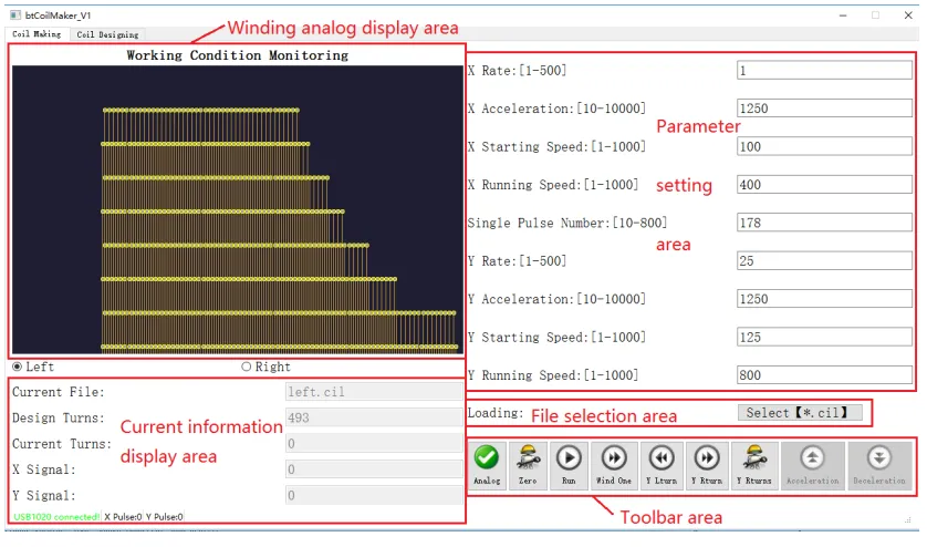
[image:4.612.97.516.134.381.2]In order to operate conveniently, this machine adopts the interface program based on Windows platform written by Qt Creator as its software control system, thus avoiding the traditional electric switch button operation. As shown in Figure 4, the control interface for the software program.
Figure 4. Software control interface.
The software program control interface consists of Parameter setting area, File selection area,
Toolbar area, Current information display area and Winding analog display area. The Parameter
setting area is used to set the velocity and acceleration of winding displacement stepper motor and
winding stepper motor, so as to control the winding speed, its Single coil pulse number refers to the number of pulses driving the winding displacement stepper motor (that is to drive the pendulum head through a line diameter distance) when the winding stepper motor turned a circle, and it is set according to different wire diameter and lead screw. The Coil file selection area is used to load the winding file, the coil file is .Cil format and can be edited by the Notepad tool that comes with the
Windows system. The Winding analog display area mainly displays the winding process. The
Current information display area shows the winding file name, the total number of coils to be
wound, the wound turns and the signal returned by the sensor. The Toolbar area has buttons such as
Analog winding, Start, Stop, and some Single winding buttons, which are used primarily for
debugging during initial coiling.
Summary
The winding machine developed in this paper is capable of winding a special-shaped electromagnetic coil. Due to the application of the stepper motor winding displacement and visual interface technology, it has the advantages of simple structure, convenient operation, high accuracy, high degree of automation, wide range of application, what’s more, it can wind different coil according to the inputting coil file.
Acknowledgement
This research was financially supported by the National Science Foundation of China (51175384) and the Key Laboratory of Digital Textile Equipment Foundation of Hubei Province (DTL2017003 and DTL2017002).
Reference
[1] Dao-yu Wan, Xiao-guang Wu, Chi Zhang, Study on needle electromagnetic force and coil profile optimization of magnetic suspension drive, J. Knitting industry. 8 (2017) 9-12.
[2] Xiao-guang Wu, Chi Zhang, Bo Yuan, Study on the force of magnetic driving needle and the magnetic coupling, J. Knitting industry. 1 (2017) 13-17.
[3] Xian-lun Yuan, Hui-bing Liu, Cheng-chao Liu, Development of micro wire winding machine, J. Modern manufacturing technology and equipment. 4 (2010) 8-9.