University of Huddersfield Repository
Li, Feng, Longstaff, Andrew P., Fletcher, Simon and Myers, Alan
A fast and effective way to improve the merging accuracy of multiview point cloud data
Original Citation
Li, Feng, Longstaff, Andrew P., Fletcher, Simon and Myers, Alan (2011) A fast and effective way
to improve the merging accuracy of multiview point cloud data. In: Proceedings of the 17th
International Conference on Automation & Computing. Chinese Automation and Computing
Society, Huddersfield, UK, pp. 1821. ISBN 9781862180987
This version is available at http://eprints.hud.ac.uk/id/eprint/11500/
The University Repository is a digital collection of the research output of the
University, available on Open Access. Copyright and Moral Rights for the items
on this site are retained by the individual author and/or other copyright owners.
Users may access full items free of charge; copies of full text items generally
can be reproduced, displayed or performed and given to third parties in any
format or medium for personal research or study, educational or notforprofit
purposes without prior permission or charge, provided:
•
The authors, title and full bibliographic details is credited in any copy;
•
A hyperlink and/or URL is included for the original metadata page; and
•
The content is not changed in any way.
For more information, including our policy and submission procedure, please
contact the Repository Team at: [email protected].
A fast and effective way to improve the merging
accuracy of multi-view point cloud data
Feng Li, Andrew Longstaff, Simon Fletcher, Alan Myers
Centre for Precision Technologies, School of Computing & EngineeringHuddersfield University
Queensgate, Huddersfield, HD1 3DH, UK [email protected]
Abstract—In reverse engineering, in order to meet the requirements for model reconstruction, it is often necessary to locate and merge the different-view-measured cloud data in a global coordinate system. Many merging methods have been proposed, the method of three datum points is one of them and the registration precision of model data depends on the precision of three datum points which are selected. This paper introduces a new development of the “centroid of apexes” method instead of the former datum points to improve the three points positioning algorithm, the effectiveness of the methods is validated with experimental results and a revised algorithm is presented.
Keywords-reverse engineering; points registration; coordinate transform; reference marker; 3-D pointsets registration
NOMENCLATURE
p q
Coordinate of feature pointsV W
Vector between pointsv
w
Unit vector
v
w
Unit vector matrixP
Coordinate of any pointR
Rotation matrixT
Translation vector
Absolute error of two edges
Relative errorINTRODUCTION
I.
The applications of three-dimensional (3D) shape measurement are widely used in the fields of industrial design and manufacturing, relic restoration, biomedicine and computer vision. There are various non-contact optical instruments involved in 3D surface measurement which are based on time-of-flight lasers [1], laser scanning [2], stereovision [3], and structured light [4]. These optical instruments can efficiently capture dense point clouds, which reveal the detail surface shape of the object being scanned. However, all of them can only obtain partial area of the object at one standpoint due to obstructions and the limited field of view of the sensor. In order to build a complete 3D model, it needs to collect point clouds acquired from different views. These multi-view scans are represented in their own local coordinate system, and geometrically aligning them to a global coordinate system is called the “registration problem”.
Solutions that are commonly used in practice for registration of multi-view Point Cloud include using datum markers, exploiting mechanical devices like turntables [5] or multi-joint robotic arms [6]. The markers can be planar or solid and are usually adhered on or near the object to be scanned. While the measuring sensor is taking point clouds from a specific view, the 3D coordinates of the markers within the view are obtained at the same time. The relative position and orientation of two scans can be easily determined if only three or more pairs of markers are visible in both views. This registration method is usually fast and reliable. However, except for the preparation work before the measurement, the drawbacks of this strategy include that the areas covered by the markers cannot be digitized reliably. This problem is outstanding especially for objects with small size and abundant details. Moreover, adhering markers on the surface is obtrusive or even prohibited in some applications.
REGISTRATION ALGORITHM BASED ON 3-D POINT
II.
SETS METHOD
Coordinate transformation of 3D graphics includes geometric transformations of translation, proportion, rotation and shear. The data alignments in this paper are only translation and rotation transformation. Since three points can express a complete coordinate, multi-view data transformation will be achieved simply with three different reference points. Besl and Mckay described manifold 3-D shape registration methods, including 3-D point sets, free-form curves and surfaces [7]. Among these methods, the 3-D point sets registration method is used in most places, especially in reverse engineering where the object shape is described as 3-D scan point sets. To carry out 3-D point sets registration, first construct least-square distance object function between the corresponding points, solve the object function based on the quaternions and the singular value decomposition (SVD) the rotation and the translation of the rigid movement [8-10].
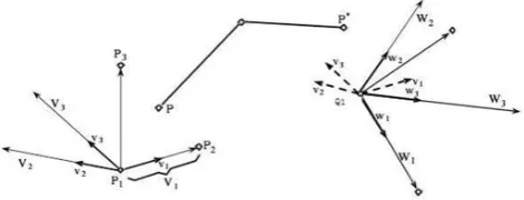
Measurement data registration can be seen as a kind of rigid body movement, so a three-point alignment coordinate transformation method can be used to deal with data registration. Because three points can establish a coordinate, we can set up three datum points of the reference markers at a different view for the data alignment. The data registration of 3D measurement data will be achieved through the alignment of three datum reference marker points. In fact, the data alignment problem is converted to coordinate transformation.
Proceedings of the 17th International Conference on
The method of three-point alignment coordinate
transformation: suppose datum feature points are
p
1,p
2and
p
3. The coordinates of the three datum points in thesecond measurement turn into
q
1,q
2 andq
3. Coordinate transformation can be achieved via three steps as derived by Mortenson and presented here for clarity [11]:1. Transform
p
1 toq
1;2. Transform vector
p
2
p
1
to
q
2
q
1
(taking only the direction into consideration);
3. Transform the plane containing the three points
1
p
,p
2andp
3to the plane containing the three pointsq
1,2
q
andq
3. The algorithm is:Step 1: Set up vector
p
2
p
1
,
p
3
p
1
,
q
2
q
1
and
q
3
q
1
(1)Step 2: Define
V
1
p
2
p
1,W
1
q
2
q
1 (2) Step 3: Set up vectorV
3andW
3
1 3 1 3 1 3 1 3q
q
W
W
p
p
V
V
(3)Step 4: Set up vector V2 and W2
1 3 2 1 3 2W
W
W
V
V
V
(4)Obviously, the vector
V
1,V
2 andV
3 constitute right-handed orthogonal lines, and the vectorW
1,W
2 andW
3also constitute right-handed orthogonal lines. Step 5: Set up unit vector
3 3 3 2 2 2 1 1 1 3 3 3 2 2 2 1 1 1,
,
,
,
W
W
w
W
W
w
W
W
w
V
V
v
V
V
v
V
V
v
(5)Step 6: Transform any point
P
i in the system
v
to the system
w
, with transformation formula:
P
*i
P
iR
T
; (6)Step 7: As
v
and
w
are unit vector matrixes,
w
v
R
,so the unknown rotation matrix about the
w
system is
v
w
R
1 ; (7)Step 8: Define
P
'
1
q
1andP
1
p
1,put them into the equation, then the translation vectorT
is obtained;
v
w
p
q
T
1
1 1 ; (8) Step 9: Equation is rewritten:
1 1 1 1 *q
w
v
p
w
v
P
[image:3.595.306.542.90.180.2]P
; (9)Fig.1 shows a three-point coordinates transformation
Figure 1. Three points to three points transformation.
Using the above re-positioning algorithm and introducing the reference points in the process of measurement, there are at least three pairs of public feature points in the measurement process, the multi-view point cloud can be precisely registered. Through two coordinate transformations based on the positioning points, the registration of two point set can be achieved.
ACCURACY ANALYSIS OF THREE-POINT
III.
POSITIONING METHOD
From the above data transformation method it can be seen that the alignment accuracy of model data depends on the measurement accuracy of three selected reference point. In addition, in the same measurement error circumstances, selection of different reference points will also affect the alignment model data. However if the error is controlled within certain range, such data transformation is able to meet the requirements of modelling and assembly.
Tao [12] proposed multiple measurement of datum points method which used two datum points and centroid as the new triangle to reduce registration error. To analyze the error of two transform method, define the vector difference of the three reference points as:
3 1 2 2 3 2 1 2 2 3 1 1 2 3 1 1 2 1
,
,
;
,
,
q
q
c
q
q
b
q
q
a
P
P
c
P
P
b
P
P
a
When measurement errors exist, because the three non-collinear points determine a triangle, if we take the conversion method based on the three reference points, in fact, it is to ensure the overlap of a point and an edge.Fig.
2 shows the situation that
P
1 andq
1 points overlap,a
1and
a
2 edges overlap and we definea
2 >a
1,c
1>c
2.Figure 2. Three datum-points alignment model.
Define: 2 1 3 2 1 2 2 1
1
a
a
,
b
b
,
c
c
(10)1 2 1
1 2 1 2 1
2 1
1
,
,
3
c
c
c
b
b
b
a
a
a
(11)From equation (11), we can draw the following two conclusions:
(1) When the measurement error is constant, the bigger area of the triangle formed by the three points, then the smaller the relative error, that means the greater distance of reference points, the smaller impact of measuring errors on data alignment;
(2) In the case of normal distribution of measurement errors, the errors of three sides tend to be the same. The relative error should tend to be equal for the same impact of the various points. That is, the selection of reference point should be as close to an equilateral triangle.
METHODS AND EXPERIMENT RESULTS
IV.
Since the error of each reference point can be seen as equal weight value, the relocation errors can be seen as average distributed errors. If we take a feature point of reference marker as the calibration reference point every time, the possibility of occurrence of human errors and accidental errors will increase greatly. Therefore, we can calculate the centroid of the vertices of reference marker and then use the centroid as the reference point to reduce registration errors. Specific methods are as follows:
Take equilateral triangle markers as artificial reference markers, there are three vertices of each reference point, shown in Fig. 3(a) and (b).
[image:4.595.302.546.205.456.2]
(a) The first measurement (b) The second measurement
Figure 3. Three points alignment based on triangle reference markers.
First, take three vertices of reference markers
A
1,B
1,1
C
as benchmark reference points, the corresponding vertices areA
'
1,B
'
1 ,C
'
1 . The coordinates of each vertex is shown in Table 1:TABLE I. VERTEX COORDINATES OF THE SELECTED REFERENCE MARKERS
Unit:mm X Coordinate Y Coordinate Z Coordinate
A1 63.751 52.445 925.525
B1 26.602 -77.182 937.412
C1 121.803 -56.026 958.979
A’1 82.544 47.635 930.928
B’1 60.090 -85.418 947.497
C’1 152.957 -52.739 966.540
We can easily get the lengths of three sides of △
1 1 1
B
C
A
and △A
'
1B
'
1C
'
1respectively,from equation (11), the relative errors can be expressed as:1 1
1 1 1 1 1
'
'
C
B
C
B
C
B
=0.0041,
2 =0.0014,3
=0.0043.Then calculate the centroid coordinates of each vertex of triangle reference markers and use centroids as the new benchmark reference point, vertex coordinates and centroid coordinates are shown in Table 2.
TABLE II. THE COORDINATES OF THE VERTICES OF REFERENCE MARKERS AND THE CENTROIDS
Unit: mm X Coordinate Y Coordinate Z Coordinate
A1 63.751 52.445 925.525
A2 62.908 45.588 926.450
A3 68.714 48.663 927.720
AO 65.125 48.899 926.565
B1 26.602 -77.182 937.412
B2 32.108 -75.148 938.562
B3 27.180 -71.638 936.488
BO 28.630 -74.656 937.487
C1 121.803 -56.026 958.979
C2 116.215 -52.159 956.649
C3 115.439 -58.752 957.885
CO 117.819 -55.646 957.838
A’1 82.544 47.635 930.928
A’2 82.639 41.045 932.060
A’3 88.507 44.432 933.298
A’O 84.563 44.370 932.096
B’1 60.070 -85.418 947.497
B’2 65.673 -82.440 948.553
B’3 59.994 -79.176 946.404
B’O 61.912 -82.345 947.485
C’1 152.957 -52.739 966.540
C’2 146.920 -49.158 964.127
C’3 146.520 -56.128 965.577
C’O 148.799 -52.675 956.415
It is easy to get the lengths of |AOBO|, |BOCO|, |COAO| and |A’OB’O|, |B’OC’O|, |C’OA’O|, calculate their relative errors:
O O
O O O O
C
B
C
B
C
B
'
'
'
1
=0.0027,2
'
=0.0010,
'
3 =0.0012.Compare of the relative errors of two measurements, as shown in Table 3:
TABLE III. THE RELATIVE ERRORS OF TWO MEASUREMENTS
The first measurement The second measurement
1
0.00411
'
0.00272
0.00142
'
0.00103
0.0043
'
3 0.0012 [image:4.595.62.284.423.525.2]points for registration. Therefore, the three points coordinate transformation method can be improved to:
Step 1: Calculate the vertex coordinates of each reference triangle (polygon) markers;
Step 2: Calculate of the centroid coordinates of triangle (polygon) reference markers;
Step 3: Use centroids to form a new of triangle;
Step 4: Turn to the front algorithm step 1, replace the three measurement benchmark points by the new triangle centroids.
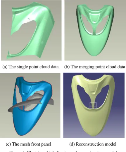
We apply the method to register scan data and reconstruct the electric vehicle shape plastic parts model from clay model in reverse engineering. Fig. 4 shows the electric vehicle front panel reconstruction model.
The first scanning data is chose as the stationary part, the other panel data is transformed to it.
(a) The single point cloud data (b) The merging point cloud data
[image:5.595.71.287.290.551.2]
(c) The mesh front panel (d) Reconstruction model
Figure 4. Electric vehicle front panel reconstruction model.
CONCLUSION
V.
Multi-view data alignment and the relocation is one of fundamental data processing problem in reverse engineering, a variety of methods has been proposed and 3-D point sets positioning method is a simple and practical
one among them. In this paper, we use the centroids instead of original vertices of reference markers to register points cloud data and apply the method to make scan data registration. Compare to other implementations the “centroid of apexes” method is more practical and time-saving. In many case, we can also use feature points on the surface of object directly instead of references markers. Experiment results show that the new method can quickly and effectively improve registration accuracy as well as being easy to use.
REFERENCES
[1] Ullrich, A., et al., Long-range high-performance time-of-flight-based 3D imaging sensors, in 3D Data Processing Visualization and Transmission2002: Padova, Italy. p. 852-855.
[2] Zexiao, X., W. Jianguo, and J. Ming, Study on a full field of view laser scanning system. International Journal of Machine Tools and Manufacture, 2007. 47(1): p. 33-43. [3] Gorpas, D., K. Politopoulos, and D. Yova, A binocular
machine vision system for three-dimensional surface measurement of small objects. Computerized Medical Imaging and Graphics, 2007. 31(8): p. 625-637.
[4] Salvi, J., J. Pagès, and J. Batlle, Pattern codification strategies in structured light systems. Pattern Recognition, 2004. 37(4): p. 827-849.
[5] Li, L., et al., A reverse engineering system for rapid manufacturing of complex objects. Robotics and Computer-Integrated Manufacturing, 2002. 18(1): p. 53-67.
[6] Larsson, S. and J.A.P. Kjellander, Motion control and data capturing for laser scanning with an industrial robot. Robotics and Autonomous Systems, 2006. 54(6): p. 453-460.
[7] P.J. Besl, N.D. McKay, A Method for Registration of 3-D Shapes, IEEE Transactions on Pattern Analysis and Machine Intelligence, vol. 14, no. 2: p. 239-256.
[8] Arun, K.S., T.S. Huang, and S.D. Blostein, Least-Squares Fitting of Two 3-D Point Sets. Pattern Analysis and Machine Intelligence, IEEE Transactions on, 1987. PAMI-9(5): p. 698-700.
[9] Faugeras, O. D., and Hebert, M. The representation, recognition, and locating 3-D objects. International Journal of Robotics Research,1986. 5(3):p. 27–52.
[10] Horn, B. K. P. Closed-form solution of absolute orientation using unit quaternions. Journal of the Optical Society of America A,1987. 4(4): p. 629–642.
[11] Mortenson, M.E., Geometric modeling, 2006: Industrial Press.