© 2016, IRJET | Impact Factor value: 4.45 | ISO 9001:2008 Certified Journal | Page 1004
“Design of Plastic Injection Mold Using Simulation Technique for
Minimizing Defect
”
Mr. Pravin.P.Shinde
1, Mr. Suresh. S. Patil
2, Mr.Sandesh.S.Awati
3Mr.Amarsingh.S. Patil
41 Assistant Professor, Mechanical Engineering Department, P.V.P.I.T. Budhgaon, 2Associate Professor, Mechanical Engineering Department, P.V.P.I.T. Budhgaon, 3Assistant Professor, Mechanical Engineering Department, P.V.P.I.T. Budhgaon 4Assistant Professor, Mechanical Engineering Department, P.V.P.I.T. Budhgaon
---***---Abstract –
This paper deals with the Design of Plastic Injection Mold Using Simulation Technique for Minimizing Defect. In analytical solution Simulation and analysis is carried out with the help of mold flow software. In this work we use Autodesk mold flow software. From the simulation and analysis, the software for flow simulation provides sufficient information regarding filling time, injection pressure, defects like air traps, weld lines, sink mark, warpage etc. With these results, users can avoid the defect of the plastic in actual injection. The analysis will help the to design a mold with minimum modifications and which will also reduce the time and cost.Key Words: Simulation, Moldflow, Housing retainer,
Weld line , Air traps
INTRODUCTION
There are different ways of molding a plastic in to desired shape. Each technique has their own advantages in the manufacturing of specific item. Injection molding is the most common and important of all plastic processing processes. The process is extremely versatile, and can produce very complex shaped parts, with the use of multi-sided molds. Even parts with metal inserts can be produced. The main concept of plastic molding is filling a molten state polymer into the mold cavity, allowed to solidify so that the polymer can take the required shape. To avoid the
high costs and time delays problems associated with the start of manufacturing, it is necessary to consider the combined effects of part geometry, material selection, mold design and processing conditions. Using predictive analysis tools to simulate the injection molding process can evaluate and optimize interactions among these variables during the design phases of a project before production begins, where the cost of change is minimal and the impact of the change is greatest.
COMPONENT DETAIL:
[image:1.595.308.525.516.732.2]© 2016, IRJET | Impact Factor value: 4.45 | ISO 9001:2008 Certified Journal | Page 1005
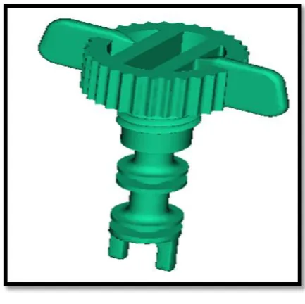
Name of Component: Housing Retainer
Molding type- Multi cavity injection mold
Material- Delrin 500P
This part is fixed at the bottom of the housing containing lubricating oil. Typically, the retainer has external treads that engages with the tapping in the Aluminum housing. The part is required to withstand the torque applied during fitment with the housing. Weld line, Warpage also needs to be controlled. The housing retainer is as shown in fig 1
ANALYTICAL SOLUTION:
The analytical formulation for a problem involves reference to the empirical and pure Engineering practices for arriving at a solution. Typically, empirical formulae that are historically developed for the application can offer a solution for the given problem.
Fig No 2 Process Related For Simulation
3D model and mold design created using CAD software such as CATIA. Meshing is carried out using pre-processor software. Analysis/ Simulation can be performed using suitable software in the CAE domain. The popular software used in the industry can be identified as Moldex / Mold Flow/ Any customized software used by Industry, etc. For the work we use Autodesk mold flow software. Flow chart for general process related for simulation is shown in fig.2
MOLD FLOW ANALYSIS:
Analysis of the product using Autodesk Mold flow (Simulation tool) software helps us validate and optimize plastic parts, injection molds, and the injection molding process. The software guides designers, mould makers, and engineers through simulation setup and results interpretation to show how changes to wall thickness, gate location, material, and geometry affect manufacturability. Simulating the injection molding process reduces the need for costly physical prototypes, avoids potential manufacturing defects and helps deliver innovative products to market faster.
Autodesk Simulation Mold flow helps to simulate the filling and packing phases of the plastic injection molding process, so we can better predict the flow behavior of melted plastics and achieve higher-quality manufacturing.
MOLD FLOW ANALYSIS RESULT:
1st Iteration
© 2016, IRJET | Impact Factor value: 4.45 | ISO 9001:2008 Certified Journal | Page 1006 mm, Gate diameter 1x3mm.The simulation result of
1st iteration is as shown in fig 3
a)
b)
c)
d)
e)
f)
© 2016, IRJET | Impact Factor value: 4.45 | ISO 9001:2008 Certified Journal | Page 1007
Fig.3: Simulation Result a) Temp. At Flow Front b) Sink Mark c) Volumetric Shrinkage d) Shear rate analysis e) Weld Line f)Air Traps g) Warpage
2nd Iteration
Results obtained from first iteration can be further optimized by changing only the gate size. Feeding system is designed with submarine gate having Cold Runner Melt Flow Channel diameter of 5 mm, Gate diameter 1x3.5mm.The simulation result of 2nd iteration is as shown in fig 4 This result are better than one but there is a scope for further optimizing the gate sizes for less defect in the component
a)
b)
c)
d)
e)
© 2016, IRJET | Impact Factor value: 4.45 | ISO 9001:2008 Certified Journal | Page 1008 g)
Fig.4: Simulation Result a) Temp. At Flow Front b) Sink Mark c) Volumetric Shrinkage d) Shear rate analysis e)Weld Line f) Air Traps g) Warpage
3rd Iteration
Since the results obtained in first and second iteration are not satisfactory, feeding system is redesigned. Feeding system is designed with pin point gate having Cold Runner Melt Flow Channel diameter of 5 mm, Gate diameter 1.2x1.5mm.The simulation result of 3rd iteration is as shown in fig 5
a)
b)
c)
d)
© 2016, IRJET | Impact Factor value: 4.45 | ISO 9001:2008 Certified Journal | Page 1009 f)
g)
Fig.5: Simulation Result a) Temp. At Flow Front b) Sink Mark c) Volumetric Shrinkage d) Shear rate analysis e)Weld Line f) Air Traps g) Warpage
Among all this iteration 3rd is the best
iteration. Minimum defects are observed in this iteration also minimum sink mark and warpage observed in iteration three. by considering this iteration the part can be molded without defects and no hesitation with the provided feed system and process conditions. So iteration three is considered for mold design.
The design is validated by producing the component with the help of the designed mold without affecting the component’s functionality. Flow of plastic will be observed. Dimensional accuracy will be measured and checked with the specified dimensions.
Visual and actual inspection will be done while attempting to identify the defects. Further, the component will be checked for fitment in the sub-assembly.
CONCLUSION:
1) The analysis will help the mold designer to design a perfect mold with minimum modifications and which will also reduce the time and cost. Thus analysis/simulation provides an insight into the nature of processing and consequently offers valuable inputs towards the design of the mold.
2) The Design of the Mold and the processing parameters has an influence over the quality of the component produced. hence while designing a mold, the designer needs to take many factors into account such as material, type of gate selection and position of gate, feed system details like gate size, sprue dimension & runner dimension and various defect such as warpage, sink mark, air traps and weld line.etc
3) Thus mold flow software is a preventive and corrective tool, helps the engineer to analyze the process to decrease the cycle time and to improve the Quality of the Product.
REFERENCES:
[1] Tuncay Erzurumlu, Babur Ozcelik “Minimization of warpage and sink index in injection-molded thermoplastic parts using Taguchi optimization method”Materials and Design vol 27, March 2005 pp 853-861
© 2016, IRJET | Impact Factor value: 4.45 | ISO 9001:2008 Certified Journal | Page 1010 element method and its time step strategies for
injection molding simulation” Computers and Chemical Engineering vol 31, December 2006 pp 1407-1418
[3] “Hamdy Hassan, Nicolas Regnier, Guy Defaye “ A 3D study on the effect of gate location on the cooling of polymer by injection molding” International Journal of Heat and Fluid Flow vol 30, June 2009 pp 1218-1229
[4] Wen-Chin Chen a, Gong-Loung Fub,c, Pei-Hao Taib, Wei-Jaw Deng d“Process parameter optimization for MIMO plastic injection molding via soft computing” Expert Systems with Applications vol 36, 2009 pp 1114–1122
[5] M.G.H.M. Baltussen, M.A. Hulsen∗, G.W.M. Peters, “Numerical simulation of the fountain flow instability in injection molding” Journal of Non-Newtonian Fluid Mechanics vol 165, March 2010 pp 631-640
[6] S.Rajalingam, Awang Bono and Jumat bin Sulaiman “A statistical experimental study on shrinkage of injection- molded part” International Journal of Humanities and Management Sciences (IJHMS) Volume 1, Issue 1, 2013 pp 2320–4044
[7] Dr.A. Riaz Ahamed, Dr.A.K. Shaik Dawood, R.Karthikeyan “Designing and optimizing the parameters which affect the molding process using Design of Experiment” International Journal of Research in Mechanical Engineering Volume 1, Issue 2, October
BIOGRAPHIES
Pravin P. Shinde is currently working as Asst. Professor at dept. of Mechanical Engineering P.V.P.I.T. Budhgaon, Sangli. He has completed M.E. in Design Engineering from P.V.P.I.T. Budhgaon, Sangli (2015) and B.E. in Mechanical Engineering from
A.I.T.R.C. Vita, Sangli(2013) and Diploma in Mechanical engineering from P.V.P.I.T. Budhgaon, Sangli (2010).
Suresh S Patil is currently working as Asso. Professor at dept. of Mechanical Engineering P.V.P.I.T. Budhgaon, Sangli, He has completed M.E. in Design Engineering from P.V.P.I.T. Budhgaon, Sangli (1996) and B.E.in
Mechanical Engineering from Karnataka, University Dharwad (1984). He has member of “Tribology society of India”. He has teaching experience for both UG and PG programs.
Sandesh S Awati is currently working as Asst. Professor at dept.of Mechanical Engineering P.V.P.I.T. Budhgaon, Sangli. He has completed M.E. in Design Engineering from
P.V.P.I.T. Budhgaon, Sangli and B.E. in Mechanical Engineering from Pvpit Budhgaon, Sangli(2013).
Amarsingh S Patil is currently working as Asst. Professor at dept. of Mechanical Engineering P.V.P.I.T. Budhgaon, Sangli. He has completed M.E. in Mechanical Design from SIT,