© 2016, IRJET | Impact Factor value: 4.45 | ISO 9001:2008 Certified Journal
| Page 1534
ENCODER ARCHITECTURE FOR LONG POLAR CODES
Laxmi M Swami
1, Dr.Baswaraj Gadgay
2, Suman B Pujari
31
PG student Dept. of VLSI Design & Embedded Systems VTU PG Centre Kalaburagi.
Email: [email protected]
2
Research Guide & Professor VTU PG Centre Kalaburagi,Karnataka,India. Email: [email protected]
3
Assistant Professor VTU PG Centre Kalaburagi, Karnataka, India.
Email:
[email protected]
Abstract:
The polar codes are considered as one of the most favorable error correcting codes because of their channel achieving property. This property helps the polar codes to handle long length codes. Implementation of fully parallel encoder is easy when code length is small, as the code length increases the hardware implementation becomes more complex. To overcome the disadvantage of fully parallel encoder partially parallel encoders were designed. This newly designed encoder handles the long polar codes with less hardware complexity. The proposed encoder can be used in the design of any polar code with any level of parallelism. The main advantage of the proposed encoder is less hardware complexity. The encoder architecture is designed and synthesis is done by using Xilinx12.2.The results are simulated by using ModelSim 10.1d simulating tool.Key words: Polar codes (PC), polar encoder, folding technique, VHDL.
1.
INTRODUCTION
Polar code belongs to linear block error correcting code. Due to less complexity in encoding and decoding algorithm it achieves the capacity of the channel [1]-[3]. For long code lengths the polar codes are considered as the best suitable error correcting codes. Because of this the polar codes are becoming the major error correcting codes in ITC. These codes are used in data storage devices. Error correcting codes protects message in storage system. The size of the message is normally 4096 byte i.e., 32768 bit but in future it is estimated to be stretched to 8192 bytes or 16384 byte. Long polar codes suffer from more hardware complexity and high latency as the message length increases.
The fundamental challenge in the ITC is achieving the capability with practical encoding. This goal is achieved by TC and LDPC. In TC coding randomness is introduced by interleaves and in LDPC by pseudo random connection
among the variable and check nodes. In order to transmit the
data from source to user over a communication channel coding techniques are used in digital communication. According to Shannon Channel capacity means the information transmitted over a channel is noise free information i.e., probability of error is zero. Bit error rate performance of LDPC codes is also nearer to Shannon limit. Polar codes are introduced by Erdal Arikan. Channel polarization phenomenon is used to achieve the encoding and decoding capacity of discrete memoryless channel. For transmitting data, decoding and encoding complexity of polar codes is O (MlogM) where M is code length. As the polar codes belong to the class of linear block codes they are mainly found in good channels with low computing complexity. Arikan had proved that according to the channel polarization phenomenon, as the block length extent to infinity the channel observed by each bit starts to polarize which means each bit approaches either a perfectly reliable channel or a noisy channel. The capacity of channel is mainly achieved by noise free bit channels. The polar codes are constructed from channel polarization phenomenon in which most of the information bits are sent over noiseless bit-channels, which are termed as excellent bit-channels, while remaining bits are set to some known value, say zero. The main advantage of the polar code is we can construct M=2m m>=1 channels that are either better or noisy for communication than the original channel by using polarizing transform on a channel m times.
© 2016, IRJET | Impact Factor value: 4.45 | ISO 9001:2008 Certified Journal
| Page 1535
more hardware. For long polar codes the fully parallelencoder is not suitable because of more hardware requirement. Only one or two bits are applied as inputs to PSN because of its successive decoding nature. Since the polar encoder obtains the input from a storage device, if the bit width of the buffer larger then, PSN is not used for scheming the polar encoders. In order to overcome the limitations of fully parallel encoder and PSN, partially parallel encoders were proposed.
The partially parallel encoder deals with long polar code. The encoding process of the polar codes is characterized by the generator matrix because they belong to class of linear block codes. By applying mth Kronecker to the kernel matrix, the GN (generator matrix) is obtained for the code length of M or 2m [1]. Folding transformation is used to implement the partially parallel encoder. The error correcting codes that achieve the capacity of DMC are the polar codes. The error correction and detection is the main objective of polar code. Polar codes are considered as the most advantageous error correcting codes because of its channel achieving property. For long codes good error correcting performance is achieved by polar codes.
With the projected encoder elevated throughput is obtained through less hardware complexity. The encoder is capable of designing any PC to any level parallelism which reduces delay element. The structural design uses the folding transformation technique to reduce the number of registers (storage device). Power consumption and hardware implementation complexity is reduced due to parallel and pipeline processing.
2. RELATED WORK
E. Arikan [1] had explained channel polarization phenomenon and SC decoding. PCs are created by using channel polarization phenomenon. Due to this channel polarization phenomenon the polar codes can handle long length messages. According to this phenomenon each of the channel approaches either a perfect consistent channel or a totally raucous channel. The main focus is on the Shannon’s capacity achieving concept. According to the capacity achieving concept the probability error of transmitting the information over a channel is approximately considered to be zero. As the polar codes belong to the class of linear codes they are characterized by generator (G) matrix.
I. Talet.al. [2]Explained SCL algorithm. This algorithm is considered as one of the most influential method that helps the polar code to achieve the good error correcting performance. This algorithm is based on likelihood or log likelihood forms. Implementation of the algorithm is more complex because it requires more hardware when these
forms are used. Because of this disadvantage log likelihood ratio based SCL is proposed. K.Chen et.al. [3] Illustrates improved successive cancellation decoding. The improved successive cancelation includes SCL and SCS decoding algorithms. These algorithms were used in path searching process of the code tree. By using these algorithms throughput of finite length PC is improved. The principles of both SCL and SCS are combined to form new algorithm know as successive cancellation hybrid (SCH). When the delay and area complexities are limited the proposed algorithm provides a flexible design. The performance maximum likelihood (ML) is achieved by the improved successive cancelation (ISC) algorithm.ISC is formed by combing of SCL, SCS and SCH.
A.J.Raymond et.al.[4] The primary ECC (Error correcting codes) with an overt construction to achieve channel capacity were discovered by Arikan. The error correction performance decreases as the length of the codes increases. For longer codes length, polar codes are designed by using SC algorithm with low hardware complexity. A new algorithm is explained in this paper which is referred as scalable successive cancellation (Ssc). For computation partial sum model is used in the proposed algorithm. Overlapping of decoding process and frame loading action are supported by designed Ssc decoder. This action reduces the requirement of bit input buffers. For long code length the proposed architecture achieves high throughput and better operating frequency because of its fixed data path. Even though the memory utilization of the designed decoder is high, use of number of logic gates and register utilization is less. The throughput of the decoder is tens of mega bits per second. G.Sarkis et.al. [5] Presented designing of FPD. The output of FPD is high compared to SC decoders. The decoder presented is 8 times faster than the currently existing polar decoder. PC performance rate is good at high SNR regions. This feature of the polar codes makes them suitable for larger data storage application. The advantage of this decoder is that it can store large data. The complexity of polar decoder is less compared to that LDPC decoder. The error correcting capability of the polar decoder is high. B.Yuan et.al. [6] Presented reformulated SC list decoding algorithm. The latency is reduced without effecting performance by reformulated algorithm. Latency reducing hardware architecture for SCL is developed based on proposed algorithm. However, due to the inbuilt serial nature of successive cancellation computation, the SCL decoders suffer from long delay and less output problems similar to premature SC decoders.
© 2016, IRJET | Impact Factor value: 4.45 | ISO 9001:2008 Certified Journal
| Page 1536
intermediate bits simultaneously. This feature reduces thelatency from one cycle to another cycle. This 2 bit reformulated approach is used to design the decoders with multibit inputs. The proposed decoder saves more clock cycles as the code rate increases. And high clock frequency is achieved because the proposed decoder uses the data path balancing technique. Hardware complexity is also reduced by with this proposed technique.
3. POLAR ENCODER
PCs are linear block ECCs. Polar codes were developed by Erdal Arikan. The channel capacity of symmetric binary input and BDMC was first achieved by using polar codes. Channel polarization phenomenon discovered by Arikan [1] is used to construct the polar code.
3.1 CHANNEL POLARIZATION
In order to create code sequences that accomplish the symmetric capacity I (w) of any specified BDMC a method is projected which is called as channel polarization phenomenon. The peak rate achievable by using i/p bits of the channel equiprobably is the symmetric capacity I (w). If channel is having some symmetry properties than the symmetric capacity becomes equal to channel capacity C (w). According to channel polarization it is probable to synthesis N self-governing copies of a given B-DMC with a dissimilar set of N binary i/p channels such that the capability of the latter set approaches either nearer to 1or nearer to 0. For channel coding second set of the data is used. When the data is sent on the channel with full rate channel capacity is nearer to 1 and at 0 rate data is sent through the other channels.
Polar codes belong to linear block codes. In the linear block codes any linear combination of codeword’s is another codeword of the code. The construction of polar codes is done by using polar transformation i.e. channel polarization. The encoding of polar code is characterized by a generator matrix G and it is given as
G=[ ]
Induction is used to define the Kronecker power of G. For any n>1 G 1=G
3.2 EXISTING METHOD
Fully parallel encoder architecture consists of four stages. Inputs are in natural order and output is bit reverse order. Construction of the polar code is done by using generator matrix since they belong to linear block codes. Generator matrix is represented by G. By pertaining nth KP
(Kronecker power) to the kernel matrix F=[ ]
generator matrix GN for code length 2m or M is obtained. Once the generator matrix is known, by using X=uGN here u and x correspond to the information and codeword vectors, correspondingly. In the following explanation codeword vector u is i/p, arranged in natural order and X which is the output codeword vector is arranged in bit reversed order. This arrangement is done in order to simplify the encoding process. The above figure1 represents fully parallel encoder architecture.
Fig-1 Structural design of 16 bit fully parallel encoder
The encoding complexity of the architecture is O(MlogM) for PC of length M. In the above architecture inputs bits are 16 and the corresponding output bits are also 16. Architecture has four stages. In order to process the information total 32 XOR gates are required which is shown in figure1. The entire encoding process is accomplished in only 1 cycle in completely parallel encoder architecture.
© 2016, IRJET | Impact Factor value: 4.45 | ISO 9001:2008 Certified Journal
| Page 1537
length increases. In order to overcome this disadvantage offully parallel architecture we go for partially parallel encoder architecture.
4. PROPOSED ARCHITECTURE
With the reduced hardware complexity an advanced architecture for long polar codes is proposed. The throughput of the proposed architecture is high therefore it can be used to design the architectures with higher level of parallelism. This architecture is best suited for long polar codes. In the proposed architecture folding transformation is used to reduce the hardware complexity.
4.1FOLDING TRANSFORMATION
Many algorithmic processes are time multiplexed into single functional unit such as adders and multiplexers by using a technique called folding transformation. This technique reduces the silicon area or the hardware complexity. A unit time processing to N is formed by folding transform and operation, here N called folding factor. In the transformed system, multiple same operations in the original system are replaced by single operation block. In the folded system a functional block is reused to perform N operations of the original system in N units of time. The control circuits for hardware are designed by using a technique called folding transformation. In this technique similar operations are replaced by a single functional unit. In DSP Data flow graph is used to implement the folding algorithm. The graph consists of functional nodes and edges. Folding set is another input of folding transformation. Operation unit original DFG is mapped with an operation of transformed DFG by the folding sets. The folding sets perform the mapping function. Latency and number of storage elements reduced by using folding sets. Thus we can say that by using folding transformation the design complexity can be reduced.
4.2 ENCODER ARCHITECTURE
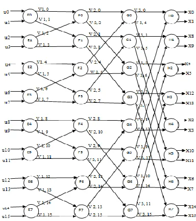
The figure2 shown below is partially parallel encoder architecture. This design is formed by applying folding transformation to fully parallel architecture. This type of illustration is called the DFG representation. Main aim of this design is to reduce the computational complexity and silicon area. The input to the encoder is in natural order and output is in bit reverse order.
Fig -2 DFG of encoder of 16 bit
The structure consists of four stages. Each stage has eight functional units. Every node performs kernel matrix operation. V k, l represents lth edge at the kth stage. The designed encoder is identical to FFT. In case of the polar encoder kernel matrix operation is performed instead of butterfly computation in FFT. The encoder process 4 bits simultaneously at same time. Each function node processes two bits at a time. Thus two nodes are to processes four bits in every stage. In the folding transformation the most important designing factor is finding the folding sets. These sets represent order of the functional nodes. In that order only the operations are executed.
[image:4.612.336.528.96.313.2]© 2016, IRJET | Impact Factor value: 4.45 | ISO 9001:2008 Certified Journal
| Page 1538
stage2 is similar to stage1.Due to this reason the order ofsets in stage2 is same i.e., {F0, F2, F4, F6} & {F1, F3, F5, F7}. The output node E0 is given as input to functional units F0, F1 of stage2. E1 node output becomes input to F0, F1.In this way every output of stage1 is passed as input to nodes of stage2. At the beginning, nodes F0 & F1 are under execution. As the encoding process proceeds each node performs the execution one after the other. The output of this stage serves as input to next stage.
In general i/p s whose indices vary by 2s-1 are processed by functional units of each stage. By using this concept the folding sets of any stage s is determined. Two input data whose indices vary by 4 are processed in stage3. The index difference represents the operational distance of the functional node. For the stage three the operational distance is two because kernel FU executes only two input data at one time. In stage3, inputs to node G0 are V2, 0 and V2, 4 which are outputs of B0 node. Similarly for G1 inputs are V2, 1 & V2, 5. This is continued for all the eight functional units of stage3. For data to be processed by functional unit both the inputs should be valid. The operations in the stage3 are delayed due to late input arrival. The functional units are fully utilized by overlapping the operations with adjacent iterations, this is done by cyclical shifting of the FSs towards right by 1 position. By placing delay of 1 time unit the overlapping concept is achieved. The order of the folding sets in stage3 is given as {G6, G0, G2, G4} & {G7, G1, G3, G5}. In other words it is right shifted version of the previous stage. The operation of the G6 node in present iteration is overlapped with the E0 and F0 in the next iteration.
In stage4 inputs applied to each node differs by indices of 8.The folding sets order is given as {H2, H4, H6, H0} & {H3, H5, H7, H1}. This order is obtained by cyclical shifting the stage3 sets towards right by two positions. Inputs of the node D0 are W3, 0 and W3, 8. Node H1 has inputs V3, 1 & V3, 9. In the same way each and every functional unit has the inputs which are having index difference of 8.
For general consideration, the folding sets are determined by taking level of parallelism into account. In above shown figure level of parallelism is four. Two conditions are required to be considered in order to determine the folding sets operational order of each stage. The first condition is stage s whose index is <=log2p, here p indicates the level of parallelism and then the stage will have the same FS as that of the earlier one. Second condition is if the index is >=log2p, then stage has the folding sets which are cyclic shifted towards right by s-log2p of previous stage i.e. s-1.For second stage, index is 2 which satisfies the first condition i.e., index is equal to
log2p therefore it is having the functional units order same as that of stage1.Second condition is applicable to stage3 and stage4 where index is greater than log2p,due to this reason their functional nodes order is cyclic shifted version of the previous stage.
4.3 RETIMING TENCHNIQUE
Without disturbing i/p and o/p characteristics of the circuits the position of the delay elements is changed by using a technique called retiming technique. For all the edges the condition DF (U V)>=0 must be fulfilled in order to realize the folding system. Before applying retiming, the folding equation DF may have (-ve) values. To satisfy the folding equation, retiming action is applied to beginning DFG before folding when the equation DF has the negative value.
4.4 REGISTER MINIMIZATION
Number of hardware FUs is reduced by a value of N by using folding technique. But this results in increased calculation time by value of N which intern results in a structural design requiring more number of registers. Thus to trim down the number of register this minimization technique was proposed. As the name indicates registers are reduced which results in the compact hardware requirement by any architecture. This technique includes two main processes, they are lifetime analysis and register allocation.
4.4.1 LIFETIME ANALYSIS
Least amount of registers required to realize a DSP algorithm in hardware is computed by using a technique called lifetime analysis. In this method numbers of variables that are live at each unit of time are worked out and highest number live variables are resoluted. For minimizing registers lifetime analysis is used in DSP applications. The life time of variable is defined as the time at which the variable is produced to till the variable is consumed. The variable is live for time period of its production to its consumption, after that variable is dead. If the lifetime of a variable is represented in linear fashion then it is a linear life time chart. Minimum number of register are required if their utmost number of live variables in linear chart.
4.4.2 REGISTER ALLOCATION
© 2016, IRJET | Impact Factor value: 4.45 | ISO 9001:2008 Certified Journal
| Page 1539
one of the above technique. In the proposed architectureforward register allocation technique is used. Variables are allocated the register in a forward manner once they are produced, allocation is continued till death of the variables or last register is reached. Periodic allocation is fallowed. If the variable is alive when it has reached the last register then that variable is allocated to register is backward manner.
Fig-3 Proposed 4stage parallel folded encoder for Polar
codes.
Figure3 consists of 12 delay elements and 8 functional units. Variables are stored in delay elements according to the register allocation table. Two FUs take the incharge of 1 stage. Hardware implementation of first and second stage is since no multiplexers are present in these two stages. In stage3 and stage4 multiplexers are present before the functional unit to configure the inputs. Four samples are processed per cycle by the proposed architecture according to register allocation table. Encoder produces the output in bit reversed order for natural order input. Thus the architecture reduces the number of delay elements. This architecture is suitable for long polar codes rather than short length codes.
5. SIMULATION RESULTS
Fig-4 RTL Schematic of folded polar encoder
Folded encoder architecture processes four inputs at a time. In the above figure Data_1, Data_2, Data_3 and Data__4 represents the inputs. These inputs are of four bits. A, B, C, D represents the outputs. S is the select line of the MUX which is used in the architecture. Reset signal is used to initialize the simulation. With this folded architecture less hardware is required since four inputs are processed at a time. Number XOR gates required and registers required are reduced.
Fig-5 16 bit encoder output
© 2016, IRJET | Impact Factor value: 4.45 | ISO 9001:2008 Certified Journal
| Page 1540
6. CONCLUSION
In this project, encoder architecture is designed by using folding technique. Fully parallel architecture is the conventional architecture, it is easy to design this architecture, but as the code length increases the number of gates required to design increases and hardware complexity also goes high. Therefore partially parallel encoder architecture with parallelism of four is designed, which reduces the hardware complexity and delay. Register allocation and retiming methods are used to shrink the hardware complexity. In the fully parallel structural design number of XOR gates required was 32 in order to design 16 bit encoder. But with the proposed architecture only four XOR gates are required.
REFERENCES
[1] E. Arikan, “Channel polarization: A method for constructing capacity achieving codes for symmetric binary-input memory less channels,” IEEE trans. vol.55, no.7, pp 3051-3073, Jul 2009.
[2] I. Tal and A. Vardy, “Successive Cancellation List Polar Decoder using Log-likelihood Ratios,” IEEE ISIT, pp 1-5, 2011.
[3] K. Chen, K. Niu, and J. Lin, “Improved successive cancellation decoding of polar codes,” IEEE trans. Commun. vol.61, no.8, pp. 3100-3107, Aug 2013.
[4] A. J. Raymond and W. J. Gross, “Scalable successive-cancellation hardware decoder for polar codes,” IEEE GlobalSIP, pp.1282-1285, Dec 2013.
[5] G. Sarkis, P. Giard, A. Vardy, C. Thibeault, and W. J. Gross, “Fast polar decoders: Algorithm and implementation,” IEEE J.Sel. Areas Commun, vol.32, no.5, pp.946-957, may 2014.