© 2015, IRJET.NET- All Rights Reserved
Page 118
Evaluation of Crankshaft Manufacturing Methods - An Overview of
Material Removal and Additive Processes
Prajakta P. Pawar
1, Dr. Santosh D. Dalvi
2, Santosh Rane
3, Dr. Chandra Babu Divakaran
41
Assistant Professor, Mechanical Engg. Department, L.T.C.O.E., Maharashtra, India
2
Assistant Professor, Production Engg. Department, F.C.R.C.E., Maharashtra, India
3
Design Head, NRB Bearing Ltd, Maharashtra, India
4
Assistant Professor, Mechanical Engg. Department, L.T.C.O.E., Maharashtra, India
---***---Abstract -
This article examines the methods ofmanufacturing of crankshaft along with their advantages and disadvantages. There are mainly three traditional methods of manufacturing crankshaft: Forging, Casting and Machining. Various disadvantages occurred while using this processes like waste of material, time requirement, it requires post processes (finishing operations) so become costly. Rapid prototyping is the best alternative to overcome all the disadvantages produced during traditional manufacturing processes. RP includes rapid tooling and rapid manufacturing. By using rapid tooling and technologies we can reduce cost and time. And rapid manufacturing is the process of automated production of any products directly from CAD data. In this paper we review all the traditional manufacturing processes of crankshaft and the alternative source in the form of Rapid manufacturing so the production should be economical in all ways.
Key Words:
Manufacturing, Crankshaft, Rapid
Prototyping.
1. INTRODUCTION
A crankshaft is an important part of an engine. It is the heart of an automotive vehicular system. A crankshaft in an internal combustion engine which converts the linear motion of the piston in to rotary motion of the flywheel. This converted rotary motion is used to drive automobile or any other device. Power from the burnt gases in the combustion chamber is used through the piston, piston pin and connecting rod. A crankshaft has a very wide range of applications from one small single cylinder engine to very large multi cylinder engines.
Amit Patil, Gajanan Datar and Amol Kolhe [10] presented a literature survey on crankshaft with its different applications made up with different materials. It is an important part in various types of engines like aerospace, reciprocating
compressors, marine engine, vehicle engine and also diesel generator.
1.1
Design and Manufacturing Considerations
Crankshaft is a large component which is complex in geometry. As the crankshaft experiences a large no of load cycles during its service life, fatigue performance and durability of this component has to be considered in the design process.
The crankshaft consists of the shaft parts which revolve in the main bearings, the crankpins to which the big ends of the connecting rod are connected, the crank arms or webs which connect the crankpins and the shaft parts. The crankshaft main journals rotate in a set of supporting bearings causing the offset rod journals to rotate in a circular path around the main journal centers. The big ends of the connecting rods contain bearings which ride on the offset rod journals. Shrikant B.Gavs, Pranit M. Patil [11] presents the prototype of mechanism using rapid prototyping processes and concluded that simulation using CAD is a safer way to design any component. The chance of failure is reduced and accuracy obtained is more.
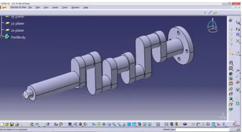
The geometrical model of crankshaft is created in Figure: 1 using CATIA V5 software. CATIA is used as a pre-processor where solid geometry is created using 2-D drawings and created 3-D model is exported as IGS file for next process.
[image:1.595.311.560.592.728.2]© 2015, IRJET.NET- All Rights Reserved
Page 119
Amit Solanki, Ketan Tamboli, M. J. Zinjuwadia [7] studied thedesign considerations and concluded that to apply the selection of material and manufacturing process need comparative study to have cost effectiveness and defects free shape respectively. In crankshaft the crack grows faster on the free surface while the central part of the crack front becomes straighter. The very prevailing mechanism of failure of crankshaft is fatigue. So the accurate stresses are critical input for fatigue. Residual imbalances along with the length of crankshaft are crucial to performance. Also the stress and strain analysis must be conducted due to the nature of load applied on crankshaft.
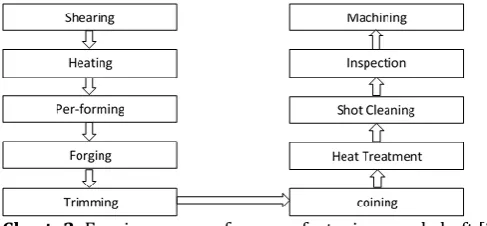
There are mainly three processes which are used for crankshaft manufacturing for metals: forging, casting, and machining. Forging is nothing but shaping of metal by plastic deformation. There are three typical stages of crankshaft forging.
Chart -1: Stages of crankshaft forging
In forging deformation is induced in each stage to ensure metal flow in to the die cavity in both top and bottom dies. The workpiece moves in a particular direction in each stage with a specific velocity. Metal flow pattern fills the complete die cavity as shown in the following chart to produce a sound forging. This process is followed by no of post processes like machining, heat treatment also.
Chart -2: Forging process for manufacturing crankshaft [2]
Casting is basically pouring the molten metal forproducing desired product. Metal is first heated at required temperature and then poured into the mould. After knockout finishing is done by machining. Crankshafts made of casting have lowest strength and it tend to be brittle. So it can be strengthened by some post-processes heat treatment and surface treatment processes.
Chart -3: Casting process for manufacturing crankshaft [4]
Machining is a material removal process from a billet with a required diameter. In this process the part is machined from a billet. This method provides flexibility of design. The billet process makes it much easier to locate the counterweights and journals webs exactly where the designer wants them to be. This process required tooling like Lathe machine, Shaper, Precision Drills, Milling machine.
Chart -4: Machining process for manufacturing crankshaft
1.2 Performance comparison of competing
manufacturing techniques
[image:2.595.35.279.518.631.2]Performance of traditional processes are compared on the basis of affecting parameters like type of material required cost of material, total time required for complete process including labour cost. By comparing all the parameters the best traditional method will be selected for manufacturing.
Table -1: Parametric comparison of processes
Sr No
Parameter
Method
Material Time Material Cost
Labour Cost
1 Forging Forged steel
Less High Less
2 Casting Cast Iron
More Less More
3 Machining Alloyed Steel
More More Less
2.
Need for Rapid Prototyping
© 2015, IRJET.NET- All Rights Reserved
Page 120
by using RP techniques. It is an automated fabricationprocess hence it requires less human interference. As the product is directly fabricated from CAD data; the product development cycle time reduces also process planning is eliminated. Zero tool costs reduces lead times and considerable gain in terms of product design. Also no tooling or fixtures required so the set up will be much easier and also lowers the overhead cost.
A survey of performance based rapid prototyping techniques is done by Deepika Jijitiya and Prabhu Lal Verma [9] and presented that the Rapid is a relative term, it may seem slow but it is much faster than the traditional processes. Currently RP can be used with some material limitations.
2.2 Prototyping and its Types
As its name suggests, the primary use of rapid prototyping is to quickly make prototypes for communication and testing purposes. Prototypes dramatically improve communication because most people, including engineers, find three-dimensional objects easier to understand than two-dimensional drawings. Such improved understanding leads to substantial cost and time savings. As Pratt & Whitney executive Robert P. Delisted noted: "We’ve seen an estimate on a complex product drop by $100,000 because people who had to figure out the nature of the object from 50 blueprints could now see it. Effective communication is especially important in this era of concurrent engineering. By exchanging prototypes early in the design stage, manufacturing can start tooling up for production while the art division starts planning the packaging, all before the design is finalized.
2.3 Rapid Prototyping, Rapid Manufacturing and
Rapid Tooling
Rapid prototyping is widely used in the automotive, aerospace, medical, and consumer products industries. Although the possible applications are virtually limitless, nearly all fall into one of the following categories: prototyping, rapid tooling, or rapid manufacturing.
The RP technique is most suitable for manufacturing of a customized or a single product.
Rapid prototyping process are divided into two fundamental process steps:
1. Generation of the mechanical layer information
2. Generation (production) of the physical layer model
The rapid prototyping techniques are classified as per addition of material, type of material, state of material used etc.
[image:3.595.310.559.150.309.2]In Figure 2 available RP processes are categorized by the base metal used for process like solid (sheets), liquid, and powder.
Fig 2: Classification of RP processes [5]
3. Durability Assessment of Crankshaft
The process parameters affects the durability of crankshaft. The evaluation was done by Zoroufi, M. and Fatemi, A. [4] incorporates material and component testing, stress and strain analysis, and fatigue or fracture analysis. Material testing incorporates hardness, monotonic, cyclic, impact, and fatigue and fracture test on specimens made from base materials. Component testing incorporates fatigue test under bending, torsion, or combined both loading conditions. Dynamic stress and strainanalysis is important to conduct due to nature of load applied on the component.
Henry et al. [3] presented a procedure to assesscrankshaft durability. The process includes four steps. The first step is modelling and load preparation that includes mesh generation, calculation of internal static loads (mass), external loads (gas and inertia) and torsional dynamic response due to rotation. The second step is the finite element method calculations including generating input files for separate loading conditions. Third step is the generation of boundary conditions file. And the final step involves the fatigue safety factor determination.
© 2015, IRJET.NET- All Rights Reserved
Page 121
6
. Cost Analysis
A cost estimation of crankshaft is calculated by Nallicheri rt al. [1] Dividing the cost of crankshaft into variable and fixed cost, they evaluate and compare the production cost of crankshaft. The common variable cost elements are cost of material, direct labour and energy. The common elements of fixed cost are cost of main machine, auxiliary equipment, tooling, building, overhead labour and maintenance. The choice of a cost effective production route for crankshaft is dependent upon two factors; first is production volume and second is the requirements of the engine.
Hoffmann and Turonek [2] analysed the cost reduction opportunities for forged steel crankshaft, with raw material cost, fatigue strength and machinability as a primary factors evaluated. In this study, a cost model supported by fatigue and machinability area and was utilized to select the lowest cost among all materials.
Sunil Jauhar, K. M. asthankar, A.M. Kuthe [8] studied the application of rapid manufacturing techniques to save the time as well as cost of manufacturing for critical automobile components. RP is an ideal method for the components which are complex in shape because it substantially compresses the time for developing prototypes and tooling, also for jig and fixtures.
7. Discussion and Conclusion
This paper provides an overview of RP technology in brief and emphasizes on their ability to shorten the product design and development process.
Classification of RP processes and details of few important processes is given. The description of various stages of data preparation and model building has been presented. An attempt has been made to include some important factors to be considered before starting part deposition for proper utilization of potentials of RP processes.
Rapid prototyping will not make machining obsolete, but rather complement it.
REFERENCES
[1] Nallicheri rt al, "Material Alternatives for the Automotive Crankshaft; A Competitive Assessment Based on Manufacturing Economics," SAE technical paper No 910139, Society of Automotive Engineers., 1991.
[2] Hoffmann and Turonek, "“High Performance Forged Steel Crankshafts - Cost Reduction Opportunities," SAE Technical Paper No. 920784 Society of Automotive Engineers., 1992.
[3] Henry, "Crankshaft Durability Prediction - A New 3-D Approach," SAE Technical Papar No. 920087, Society of Automotive Engineers, 1992.
[4] FATEMI, "A LITERATURE REVIEW ON DURABILITY EVALUATION OF CRANKSHAFTS INCLUDING COMPARISONS OF COMPETING MANUFACTURING PROCESSES AND COST ANALYSIS," in 26th Forging Industry Technical Conference, chicago, 2005. [5] R. L. Ju¨rgen Stampfl, "New Materials for Rapid
Prototyping Applications," WILEY-VCH Verlag GmbH & Co. KGaA, Weinheim, pp. 1253-1256, 2005.
[6] Dilip Sahebrao Ingole, "Rapid prototyping – a technology transfer approach for development of rapid tooling," Rapid Prototyping Journal Emerald Group Publishing Limited, vol. 13, no. 3, pp. 280-290, 2009. [7] Amit Solanki, Ketan Tamboli, M. J. Zinjuwadia
"Crankshaft Design and Optimization- A Review," in National Conference on Recent Trends in Engineering & Technology, Gujarat, 2011.
[8] Sunil Jauhar, K. M. asthankar, A.M. Kuthe "Cost benefit analysis of Rapid Manufacturing in Automotive Industries," Advances in Mechanical Engineering and its Applications (AMEA), vol. 2, no. 3, pp. 181-188, 2012.
[9] Deepika Jijotiya and Dr. Prabhu Lal Verma, "A Survey of Performance based Advanced Rapid Prototyping Techniques," Scholars Journal of Engineering and Technology (SJET), pp. 4-12, 2013.
[10]Amit Patil, Gajanan Datar, Amol Kolhe "CRANKSHAFT FAILURE DUE TO FATIGUE—A REVIEW," International journal of mechanical engineering and Robotics research, vol. 3, no. 1, pp. 166-172, 2014.
[11]Shrikant B. Gawas Mr. Pranit M. Patil, "Prototype of Mechanisms using Fused Deposition Modelling Process," INTERNATIONAL JOURNAL OF ENGINEERING SCIENCES & RESEARCH TECHNOLOGY, pp. 438-442, 2014.
© 2015, IRJET.NET- All Rights Reserved
Page 122
BIOGRAPHIES
Prajakta P Pawar is a Research Scholar in the department of Mechanical Engineering at L.T.C.O.E Navi Mumbai with specialization in Manufacturing. Prajakta Pawar is a professional member of IIIE.
Dr. Santosh D. Dalvi is PhD in Mechanical Engineering and currently working as Assistant Professor at F.C.R.C.E. Mumbai. Dr. Santosh Dalvi is interested in energy efficiency, energy conservation and energy management. Dr. Dalvi is Professional member of ISTE, IIIE, and NBT.
Mr. Santosh Rane is Currently working in NRB Bearing Ltd. as a Design Head and having 13.5 years industry experience. Mr. Rane currently works on Design and development of bearings for on road and off road vehicle powertrain.
![Fig 2: Classification of RP processes [5]](https://thumb-us.123doks.com/thumbv2/123dok_us/8210153.818167/3.595.310.559.150.309/fig-classification-of-rp-processes.webp)
