© 2016, IRJET | Impact Factor value: 4.45 | ISO 9001:2008 Certified Journal | Page 1652
Collision Aware Application Specific Path Controller for FANET with
Variance Method
Poonam
1, Navjot Kaur
21
M.Tech (CSE),Doaba Group of Colleges, Kharar
2
M.Tech (CSE, HOD),Doaba Group of Colleges, Kharar
Abstract: The flying ad-hoc networks (FANET) are utilized
in the various types of applications, such as weather, military, information retrieval, geographic information systems (GIS), surveillance of disaster hit area, etc. The groups of unmanned aerial vehicles, also called flying nodes or crafts, are used for such applications. The flying nodes or crafts, when take the flight, need to consider multiple factors altogether for the information collection for the targeted applications. The major factors are the path planning, collision avoidance, target coverage and remaining fuel or battery power. The path planning for the target coverage is calculated entirely based upon the remaining power or fuel and target locations. The takeoff and landing positions are taken as the pre-decided data for the topological scenario. The path planning methodology requires the information about the 3-D coordinates of the crafts, which also include the height of the flight as the third dimension. The flying node flight must be arranged in the collision free manner, which requires the number of computations altogether, which computes the current point to target point path by analyzing the remaining power, path length, points of collisions, etc. In this paper, the proposed FANET control system has been designed for the complete control of the crafts during the flights. The points of collisions, takeoff and landing are selected on the basis of multifactor input data after the abundance of the calculation altogether. The proposed model has been tested with many performance parameters and it has performed perfectly well in the terms of time complexity, number of bypass decisions, etc. The proposed model has outperformed the existing models for the collision free routing in the FANETs.
Keywords: FANET Routing, Craft collision control, Adaptive path planning, collision free routing.
I.
I
NTRODUCTIONAn unmanned aerial vehicle (UAV), commonly known as a drone and also referred to as an unpiloted aerial vehicle and a remotely piloted aircraft (RPA) by the International Civil Aviation Organization (ICAO), is an aircraft without a
human pilot aboard. ICAO classifies unmanned aircraft into two types under Circular 328 AN/190:
Autonomous aircraft – currently considered unsuitable for regulation due to legal and liability issues.
Remotely piloted aircraft – subject to civil regulation under ICAO and under the relevant national aviation authority.
© 2016, IRJET | Impact Factor value: 4.45 | ISO 9001:2008 Certified Journal | Page 1653 the environment, which results in even harder stochastic
control problems.
Path planning for small Unmanned Aerial Vehicles (UAVs) is one of the research areas that has received significant attention in the last decade. Small UAVs have already been field tested in civilian applications such as wild-fire management, weather and hurricane monitoring and pollutant estimation where the vehicles are used to collect relevant sensor information and transmit the information to the ground (control) stations for further processing. Compared to large UAVs, small UAVs are relatively easier to operate and are significantly cheaper. Small UAVs can fly at low altitudes and can avoid obstacles or threats at low altitudes more easily. Even in military applications, small vehicles are used frequently for intelligence gathering and damage assessment as they are easier to fly and can be hand launched by an individual without any reliance on a runway or a specific type of terrain.
Even though there are several advantages with using small platforms, they also come with other resource constraints due to their size and limited payload. As small UAVs typically have fuel constraints, it may not be possible for an UAV to complete a surveillance mission before refueling at one of the depots. For example, consider a typical surveillancemission where a vehicle starts at a depot and
is required to visit a set of targets. To
complete this mission, the vehicle may have to start at the depot, visit a subset of targets and then reach one of the depots for refueling before starting a new path. One can reasonably assume that once the UAV reaches a depot, it will be refueled to full capacity before it leaves again for visiting any remaining targets. If the goal is to visit each of the given targets at least once, then the UAV may have to repeatedly visit some depots in order to refuel again before visiting all the targets.II. LITERATUREREVIEW
2014 Manyam, Satyanarayana G. et. al. [1] have proposed the routing algorithm for two Unmanned Aerial Vehicles with communication constraints. Contact with UGS is strictly maintained, which allows the UGS act as beacons for relative navigation eliminating the need for dead reckoning. This problem is referred to as the Communication Constrained UAV Routing Problem (CCURP). To solve the CCURP, shortest paths between targets are computed by means of a graph transformation. Given the shortest paths between targets, two solution methods are presented. 2014 Sundar, Kaarthik, and Sivakumar Rathinam [2] have proposed an algorithms for routing an unmanned aerial vehicle in the presence of
refueling depots. The objective of the problemis to find a path for the UAV such that each target is visited at least once by the vehicle, the fuel constraint is never violated along the path for the UAV, and the total fuel required by the UAV is a minimum. 2014 Hernandez-Hernandez, Lucia, Antonios Tsourdos, Hyo-Sang Shin, and Antony Waldock [3] have worked on multi-Objective UAV routing method. The purpose of the study, presented in this paper, has been to apply a multi-objective graph-based method for plan routes of a simulated UAV taking into account scenarios with danger zones or prohibited areas, characteristic of civil airspace, as well as areas with time and speed restrictions and some negotiable “safe corridors”. 2010 Klein, Daniel J., Johann Schweikl, Jason T. Isaacs, and Joao P. Hespanha. [4] have worked on UAV routing protocols for sparse sensor data exfiltration. The problem addressed in this paper is data exfiltration from a collection of sensors that are unable to establish ad-hoc communication due to their widespread deployment, geographical constraints, and power considerations. Sensor data is exfiltrated by one or more uninhabited aerial vehicles (UAVs) that act as data mules by visiting each sensor in order to establish a communication link.
2008 Ny, Jerome Le, Munther Dahleh, and Eric Feron [5] have done their research on multi-UAV dynamic routing with partial observations using restless bandit allocation indices. Motivated by the type of missions currently performed by unmanned aerial vehicles, we investigate a discrete dynamic vehicle routing problem with a potentially large number of targets and vehicles.
III. EXPERIMENTALDESIGN
© 2016, IRJET | Impact Factor value: 4.45 | ISO 9001:2008 Certified Journal | Page 1654 by the collision free path planning mode for FANETs under
the proposed model.The fuel-out situation must be avoided under the path planning models for the FANETs. The fuel-out situation will become the reason of the air craft crashes, hence to avoid the crashes, the regular fuel tracking and path planning updation is very much required under the proposed model. The proposed model has been designed for the optimal path planning under the multivariate path calculation. The alternate trip is also accounted if something happened over the path, such as long bypass due to the collision avoidance, fuel leakage, etc, which re-accounts the path calculation factoring for the purpose of successful flight.
The distance is the primary factor for the path evaluation. The distance between the two physical points is usually calculated using the location coordinates. The 3-D path planning requires the three numbers of coordinates, which includes the latitude (X), longitude (Y) and elevation of flight (Z). In this paper, the proposed model utilizes the distance for the path planning, collision avoidance and other such applications, which requires the adaptive distance calculation for the optimal path planning, collision prediction, backup path planning, etc. The hurdles are detected over the paths by using the regular object distance mapping as well as the other flying object positions. The collision prediction and hurdle detection method categorizes the hurdles in the form of moving or static hurdles. The proposed model evaluates the possibility for the hurdles and updates the path according on every moment. The distance between the two points is calculated by using the 3-D coordinates as explained in the
path
planning method. The following equation is
utilized for the calculation of the adaptive distance:
Distance =
Where the X1, Y1 and Z1 represents the location coordinates of the one node, which denotes the latitude, longitude and elevation of the point or air crafts. The X2, Y2 and Z2 represents the points of the other node.The course of the movement is the continuous process for the evaluation of the position coordinates, even if the hurdles exist or not over the given path. The collision prediction is incorporated by monitoring and analyzing the intersection points between the flights of the crafts and the arrival of the air craft nodes on those points according to the timeline. The time of arrival on the intersection points for the two or more aircrafts predict the collisions, which must be avoided by making the slight changes into the path of one of the aircrafts flying towards the same
destination. The proposed model is entirely based upon the collision prediction for the purpose of computing the solution to avoid the collision predicted by the system. The following algorithm defines the course of action for the whole path planning methodology for the application specific path panning with collision awareness system:
Algorithm 1: Collision Prediction based Path Planning Algorithm (CP-3)
1. The simulation begins
2. Nodes start their communication module.
3. The aircraft node searches for the ground controller units (GCU).
4. The request is forwarded to the GCU. 5. The GCU replies with the acknowledgement. 6. Node replies with its current location coordinates. 7. The GCU updates the node information.
8. GCU assign the membership to the node requesting for membership.
9. GSU request other nodes in the cluster.
10. The node are request to update the locations periodically (in the period of ten to one thousand milliseconds)
11. Request the FANET nodes to return their current locations.
12. The node positions are extracted in the X, Y and Z arrays.
13. Evaluate the course of movement of each node in the FANET cluster.
14. Notify the points of intersection for the two or more nodes.
15. Calculate the time of the arrival for each of the aircraft on every intersection.
16. If two or more aircrafts arrival time matches by the variance
© 2016, IRJET | Impact Factor value: 4.45 | ISO 9001:2008 Certified Journal | Page 1655 b. Compute the requirement of the variance
in the flight path.
c. Apply the variance on each aircraft other than the nearest node.
17. Continuously detect the course of action.
18. The course of action will return the distant steady objects in the path.
19. The distance is calculated from the steady hurdle object.
20. The variance is computed to avoid the hurdle. 21. Apply the variance to the aircraft.
22. Update the path information of the given aircraft.
IV. RESULTANALYSIS
The results analysis is the analysis of the proposed model on the basis of various performance parameters. The performance parameters are the specified entities which defines the result of the implemented model. The performance parameters have to be selected on the basis of the nature of the project, algorithms being used and the testing data. The result analysis of the proposed model has been entirely based upon the various network performance parameters. The network performance parameters of throughput, delay, network load, packet delivery ratio and data drop rate has been obtained from the proposed model simulation.
Throughput
Throughput or Network throughput is the ratio of total amount of data (which receives by the receiver from the sender) to the time it takes for the receiver to receive the last packet. It is represented in bytes per second or packets per seconds.
Throughput= Eq. (1)
Where, t = Time interval
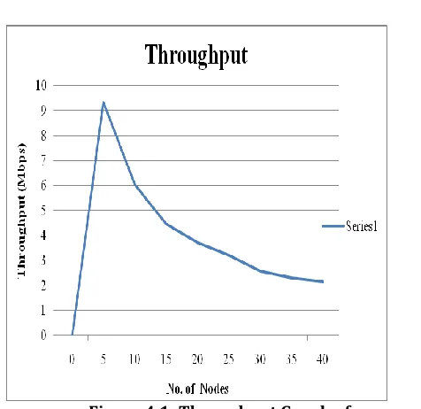
Figure 4.1: Throughput Graph of proposed model simulation
[image:4.612.321.559.93.324.2]The throughput graph has been obtained from the simulation parameters. The throughput as shown in the Figure 4.1 has been recorded on the interval on every 0.5 seconds for the proposed UAV path planning simulation. The maximum throughput has been recorded nearly at 9.0 Mbps which show efficient and high performance of the FANET path planning method.
End to End Delay
The end-to-end delay is the time from the generation of a packet by the source up to the destination reception, so this is the time that a packet takes to go across the network. This time is expressed in seconds (sec).
Delay= Eq. (2)
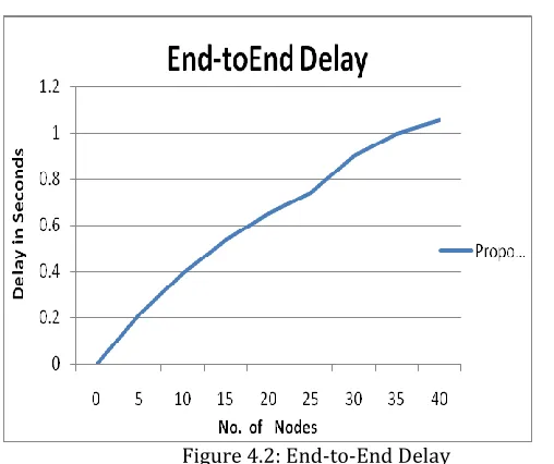
© 2016, IRJET | Impact Factor value: 4.45 | ISO 9001:2008 Certified Journal | Page 1656 Figure 4.2: End-to-End Delay
The end to end delay has been recorded in the form of increasing curve as shown in the Figure 4.2. The latency increases with the rise in the traffic volumes. The traffic volumes have been increased gradually with the increase in the attacker nodes.
Network Load
Network Load is the amount of data (traffic) being carried by the network at a particular time. The network load varies from time to time. It is represented in bytes per second or packets per seconds.
Network Load= Eq. (3) Where, t = Time Interval
Figure 4.3: Network Load
The network load is the indicator of the resource engagement. The higher resource engagement increases the computational delay, which directly affects the performance of the VANET model as shown in the Figure 4.3.
5.2.1 Packet Delivery Ratio
Packet delivery ratio is calculated by dividing the number of packets received by the destination through the number of packets generated or sent from the source. It describes the loss rate. The Performance is better when packet delivery ratio is high.
PDR= Eq. (4)
[image:5.612.35.289.100.313.2]© 2016, IRJET | Impact Factor value: 4.45 | ISO 9001:2008 Certified Journal | Page 1657
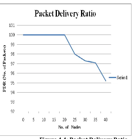
Figure 4.4: Packet Delivery Ratio
The packet delivery ratio is the parameter to indicate the successfully propagated data in comparison with the data volumes from the sender’s node. The higher packet delivery ratio indicates the high trust factor of the given network as shown in the Figure 4.4. The higher packet delivery ratio indicates the high trust factor of the given network as shown in figure 4.4. The PDR has been recorded more than 95% in the proposed model simulation.
V. CONCLUSIONANDFUTUREWORK
The existing algorithm approximates the path but the path direction is according to the line of path connecting the grid points in the graph grid for path selection. The existing routing algorithm and collision avoidance method does not evaluate the 3-D positioning of the UAVs. The proposed algorithm has calculated the shortest UAV path with the collision free environment for the establishment of the FANET cluster, which has been programmed to direct the UAV to fly from one point to other point as straight as maximum possible. Also the proposed path planning solution with collision avoidance ability based model evaluates the 3-D position of the UAVs, which has been programmed to allow them to overpass the UAVs without being confused with the points of collision. The points of collision has been clearly defined and avoided in the proposed model. The proposed model has been tested for the its performance using the many performance parameters. The proposed model has been evaluated for its efficiency and found approximately 20% efficient in lowering the possibility of collision across the cluster, and
improves the overall reaction time by 15% on an average. Hence, this signifies the robustness of the proposed model in providing the collision free environment for the proposed model path planning method for the FANETs under the proposed model.
REFERENCES
[1] Manyam, Satyanarayana G., Sivakumar Rathinam, Swaroop Darbha, David Casbeer, and Phil Chandler. "Routing of two Unmanned Aerial Vehicles with communication constraints." In Unmanned Aircraft Systems (ICUAS), 2014 International Conference on, pp. 140-148. IEEE, 2014.
[2] Sundar, Kaarthik, and Sivakumar Rathinam. "Algorithms for routing an unmanned aerial vehicle in the presence of refueling depots." (2014): 1-8.
[3] Hernandez-Hernandez, Lucia, Antonios Tsourdos, Hyo-Sang Shin, and Antony Waldock. "Multi-Objective UAV routing." In Unmanned Aircraft Systems (ICUAS), 2014 International Conference on, pp. 534-542. IEEE, 2014. [4] Klein, Daniel J., Johann Schweikl, Jason T. Isaacs, and Joao P. Hespanha. "On UAV routing protocols for sparse sensor data exfiltration." In American Control Conference (ACC), 2010, pp. 6494-6500. IEEE, 2010.
[5] Ny, Jerome Le, Munther Dahleh, and Eric Feron. "Multi-UAV dynamic routing with partial observations using restless bandit allocation indices." In American Control Conference, 2008, pp. 4220-4225. IEEE, 2008.
[6] Karaman, S., and E. Frazzoli. "Linear temporal logic vehicle routing with applications to multi‐UAV mission planning." International Journal of Robust and Nonlinear Control 21, no. 12 (2011): 1372-1395.
[7] Quintero, Steven AP, Francesco Papi, Daniel J. Klein, Luigi Chisci, and João Pedro Hespanha. "Optimal UAV coordination for target tracking using dynamic programming." In Decision and Control (CDC), 2010 49th IEEE Conference on, pp. 4541-4546. IEEE, 2010.