Optimization Technique for Power Quality Improvement
Using DSTATCOM
Vasanthavalli.C
*, Vellaisamy.S
*** Post -Graduate scholar, Department Of Power Electronics And Drives, SCAD College of Engineering and Technology, Tirunelveli.
**
Professor, Department Of Electrical and Electronics Engineering, SCAD College of Engineering and Technology, Tirunelveli.
Abstract- An implementation of a three phase distribution static compensator (DSTATCOM) using a control algorithm for its functions under nonlinear loads such as load balancing and reactive power compensation for power factor, and zero voltage regulation. A control algorithm is used for the extraction of the fundamental weighted value of active and reactive power components. Using digital signal processor the DSTATCOM is developed and its performance of DSTATCOM is found to be satisfactory for various types of loads.
Index Terms- Control algorithm, harmonics, load balancing, power quality, weights.
I. INTRODUCTION
he quality of available supply power has a direct economic impact on industrial and domestic sectors which affects the growth of any nation [1]. This issue is more serious in electronic based systems. The level of harmonics and reactive power demand are popular parameters that specify the degree of distortion and reactive power demand at a particular bus of the utility [2]. The harmonic resonance is one of the most common problems reported in low and medium-level distribution systems. It is due to capacitors which are used for power factor correction (PFC) and source impedance [3]. Power converter-based custom power devices (CPDs) are useful for the reduction of power quality problems such as PFC, harmonic compensation, voltage sag/swell compensation, resonance due to distortion, and voltage flicker reduction within specified international standards [4]–[6]. These (CPDs) include the distribution static compensator (DSTATCOM), dynamic voltage restorer, and unified power quality conditioner in different configurations [7]–[9]. Some of their new topologies are also reported in the literature such as the indirect matrix converter based active compensator where the dc-link capacitor can be removed [10]. Other new configurations are based on stacked multicell converters where the main features are on the increase in the number of output voltage levels, without transformer operation and natural self-balancing of flying capacitor voltage, etc. [11]. The performance of any custom power device depends very much upon the control algorithm used for the reference current estimation and gating pulse generation scheme.
Many non model and training-based alternative control algorithms are reported in the literature with application of soft computing technique such as neural network, fuzzy logic and adaptive neuro-fuzzy, etc. [17]–[20]. Adaptive learning, self organization, real-time operation, and fault tolerance through
redundant information are major advantages of these algorithms. A neural network-based control algorithm such as the Hopfield-type neural network is also used for the estimation of the amplitude and phase angles of the fundamental component both with highly distorted voltage by the assumption of known power frequency. An improved adaptive detecting approach for the extraction of the error signal with variable learning parameters can be chosen for fast response to improve tracking speed and for a low value in a stable period to improve accuracy. Wu et al have proposed a new control algorithm based on inverse control with a neural network interface which was applied for the instantaneous calculation of switching on–off time in a digital environment. A survey on iterative learning control (ILC) is presented by Ahn et al., and it is classified into different subsections within the wide range of application. The main idea of ILC is to find an input sequence such that the output of the system is as close as possible to a desired output. Control algorithms reported in available texts such as the quantized Kernel least mean square algorithm , radial basis function (RBF) networks, and feed forward training can also be used for the control of CPDs. An immune RBF neural network integrates the immune algorithm with the RBF neural network. This algorithm has the advantages in the learning speed and accuracy of the astringent signal. Therefore, it can detect the harmonics of the current timely and precisely in the power network [28]. A multilayer perceptron neural network is useful for the identification of nonlinear characteristics of the load. The main advantage of this method is that it requires only waveforms of voltages and currents. A neural network with memory is used to identify the nonlinear load admittance. Once training is achieved, the neural network predicts the true harmonic current of the load when supplied with a clean sine wave. Its application with SRF theory is described by Mazumdar
et al. Feedforward back propagation (BP) artificial neural network (ANN) consists of various layers such as the input layer, hidden layer, and output layer. It is based on feedforward BP with a high ability to deal with complex nonlinear problems. The BP control algorithm is also used to design the pattern classification model based on decision support system. The standard BP model has been used with the full connection of each node in the layers from input to the output layers.
Some applications of this algorithm are as to the identification of user faces, industrial processes, data analysis, mapping data, control of power quality improvement devices, etc. The control of power quality devices by neural network is a latest research area in the field of power engineering. The extraction of harmonic components decides the performance of compensating devices. The BP algorithm which trained the sample can detect the signal of the power quality problem in real
time. Its simulation study for harmonic detection is presented in [20].
Many neural network-based algorithms are reported with theoretical analysis in single phase system, but their implementation to DSTATCOM is hardly reported in the available literature. In this paper, a BP algorithm is implemented in a three phase shunt connected custom power device known as DSTATCOM for the extraction of the weighted value of load active power and reactive power current components in nonlinear loads. The proposed control algorithm is used for harmonic suppression and load balancing in PFC and zero voltage regulation (ZVR) modes with dc voltage regulation of DSTATCOM. In this BP Algorithm, the training of weights has three stages. It includes the feedforward of the input signal training, calculation and BP of the error signals, and upgrading of training weights.
It may have one or more than one layer. Continuity, differentiability, and non decreasing monotony are the main characteristics of this algorithm. It is based on a mathematical formula and does not need special features of function in the learning process. It also has smooth variation on weight correction due to batch updating features on weights. In the training process, it is slow due to more number of learning steps, but after the training of weights, this algorithm produces very fast trained output response. In this application, the proposed control algorithm on a DSTATCOM is implemented for the compensation of nonlinear loads.
II. SYSTEMCONFIGURATIONANDCONTROL
ALGORITHM
A voltage source converter(VSC)-based DSTATCOM is connected to a three phase ac mains feeding three phase linear/nonlinear loads with internal grid impedance which is shown in Fig. 1. The performance of DSTATCOM depends upon the accuracy of harmonic current detection. For reducing ripple in compensating currents, the tuned values of interfacing
inductors (
L
f) are connected at the ac output of the VSC. Athree phase series combination of capacitor (
C
f)and aresistor(
R
f )represents the shunt passive ripple filter which is connected at a point of common coupling (PCC) for reducing the high frequency switching noise of the VSC. The DSTATCOMcurrents (
i
Cabc) are injected as required compensating currents tocancel the reactive power components and harmonics of the load currents so that loading due to reactive power component/harmonics is reduced on the distribution system. For the considered three phase nonlinear load with approximately 24kW, the compensator data are given in Appendix A.
Fig. 1.Schematic diagram of VSC-based DSTATCOM.
Fig. 2 shows the block diagram of the BP training algorithm for the estimation of reference source currents through the weighted value of load active power and reactive power current components. In this algorithm, the phase PCC voltages (), source
currents (
i
sa,
i
sb,
i
sc), load currents (i
La,
i
Lb,
i
Lc) and dc busvoltage (
v
dc) are required for the extraction of reference sourcecurrents.
There are two primary modes for the operation of this algorithm: The first one is a feedforward, and the second is the BP of error or supervised learning.
A. Estimation of Weighted Value of Average Fundamental Load Active and Reactive Power Components
A BP training algorithm is used to estimate the three phase weighted value of load active power current components
(
w
ap,
w
bp,
w
cp) and reactive power current components(
w
aq,
w
bq,
w
cq) from polluted load currents using theThe detail application of this algorithm for the estimation of various control parameters is given as follows.
cp lc bp Lp ap La o
Lap
w
i
u
i
u
i
u
i
(1)
cp lc bp Lp ap La o
Lbp
w
i
u
i
u
i
u
i
(2)
cp lc bp Lp ap La o
Lcp
w
i
u
i
u
i
u
i
(3)
Where Wo is the selected value of the initial weight
and(
u
ap,
u
bp,
andu
cp)are the in-phase unit templates. In-phase unit templates are estimated using sensed PCC phase voltages(
v
sa,
v
sb,
v
sc). It is the relation of the phase voltage and theamplitude of the PCC voltage (
v
t). The amplitude of sensedPCC voltages is estimated as
2
(
)
/
3
2 2 2
sc sb sa
t
v
v
v
v
(4)
The in-phase unit templates of PCC voltages
cp bp
ap
u
andu
u
,
,
are estimated as [13]
t
sa ap
v
v
u
t sb bp
v
v
u
t sc cp
v
v
u
(5)
The extracted values of
I
Lap,
I
Lbp,
I
Lcp are passed through a sigmoid function as an activation function, and the outputsignals (
z
ap,
z
bp,
z
cp) of the feedforward section are expressed as)
(
Lapap
f
I
Z
(6)
)
(
Lap bpf
I
Z
(7)
)
(
Lap cpf
I
Z
(8)
The estimated values of (
z
ap,
z
bp,
z
cp) are fed to a hidden layer as input signals. The three phase outputs of this layer(
I
Lap1,
I
Lbp1,
I
Lcp1) before the activation function are expressed as
I
ap1
w
01
w
apZ
ap
w
bpZ
bp
w
cpZ
cp (9)
I
bp1
w
01
w
bpZ
bp
w
cpZ
cp
w
apZ
ap (10)
I
cp1
w
01
w
cpZ
cp
w
apZ
ap
w
bpZ
bp (11)Where(
w
01,w
ap,
w
bp,
w
cp) are the selected value of theinitial weight in the hidden layer and the updated values of three
phase weights using the average weighted value (
w
p) of the active power current component as a feedback signal, respectively. The updated weight of phase “a” active powercurrent components of load current “
W
ap” at the nth samplinginstant is expressed as
where
w
p(n) andw
ap1(n) are `the average weighted value of the active power component of load currents and the updated weighted value of phase “a” at the nth sampling instant, respectively and wap1(n) and zap(n) are the phase “a”fundamental weighted amplitude of the active power component of the load current and the output of the feed forward section of the algorithm at the nth instant, respectively. f(Iap1) and μ are represented as the derivative of Iap1 components and the learning rate. Similarly, for phase “b” and phase “c,” the updated weighted values of the active power current components of the load current are also expressed as same. The extracted values of
Iap1, Ibp1, and Icp1 are passed through a sigmoid function as an activation function to the estimation of the fundamental active components in terms of three phase weights wap1, wbp1, and
wcp1 as
(
)
)
(
)
(
1 1 1 1 1 1 cp cp bp bp ap apI
f
w
I
f
w
I
f
w
B. Amplitude of Active Power Current Components of Reference Source Currents
An error in the dc bus voltage is obtained after comparing
the reference dc bus voltage
(
)
*n
v
dc and the sensed dc busvoltage
v
dc of a VSC, and this error at the nth sampling instantis expressed as
v
de(
n
)
v
dc(
n
)
v
dc(
n
)
(13)
This voltage error is fed to a proportional–integral (PI) controller whose output is required for maintaining the dc bus voltage of the DSTATCOM. At the nth sampling instant, the output of the PI controller is as follows:
(n) dc v id K 1)} (n dc v (n) dc {v pd K 1) (n dp w (n) dp
w
(14)
Where
k
pd andk
id are the proportional and integral gainconstants of the dc bus PI controller.
v
de(n) andv
de (n − 1) arethe dc bus voltage errors in the nth and (n − 1)th instant, and
dp
w
(n) and
w
dp(n − 1) are the amplitudes of the active power component of the fundamental reference current at the nth and (n − 1)th instant, respectively. The amplitude of the active powercurrent components of the reference source current (
w
spt) is estimated by the addition of the output of the dc bus PI controller(
w
dp) and the average magnitude of the load active currents(
w
Lpa) as
C. Amplitude of Reactive Power Components of Reference Source Currents
An error in the ac bus voltage is achieved after comparing
the amplitudes of the reference ac bus voltage
v
*t and thesensed ac bus voltage
v
t of a VSC. The extracted ac bus voltageerror
v
te at the nth sampling instant is expressed as
v
te(n)
v
t(n)
v
t(n)
(16)
The weighted output of the ac bus PI controller
w
qq for regulating the ac bus terminal voltage at the nth sampling instant is expressed as(n) te v it K 1)} (n te v (n) te {v pt K 1) (n qq w (n) qq
w
(17)
where
w
qq(n) is part of the reactive power component of thesource current and it is renamed as
w
qq.k
pt andk
it are theproportional and integral gain constants of the ac bus voltage PI controller. The amplitude of the reactive power current
components of the reference source current
w
sqt is calculated bysubtracting the output of the voltage PI controller
w
qq and theaverage load reactive currents
w
Lqa as
w
spt
w
qq
w
Lqa (18)D. Estimation of Reference Source Currents and Generation of IGBT Gating Pulses
Three phase reference source active and reactive current components are estimated using the amplitude of three phase (a, b, and c) load active power current components, PCC voltage in-phase unit templates, reactive power current components, and PCC quadrature voltage unit templates as
i
sap
w
sptu
api
sbp
w
sptu
bpi
scp
w
sptu
cp (19)
i
saq
w
sqtu
aqi
sbq
w
sqtu
bpi
scq
w
sqtu
cp (20)The addition of reference active and reactive current components is known as reference source currents, and these are given as
saq sap
sa
i
i
i
*
i
sb
i
sbp
i
sbq *
i
sc
i
scp
i
scq *(21)
signals are amplified through PI current regulators; their outputs are fed to a pulse width modulation (PWM) controller to generate the gating signals for insulated-gate bipolar transistors (IGBTs) S1 to S6 of the VSC used as a DSTATCOM.
III. SIMULATIONRESULTSANDDISCUSSION
MATLAB with SIMULINK and Sim Power System toolboxes is used for the development of the simulation model of a DSTATCOM and its control algorithm. The performance of the BP algorithm in the time domain for the three phase DSTATCOM is simulated for PFC and ZVR modes of operation under nonlinear loads. The performance of the control algorithm is observed under nonlinear loads.
A. Performance of DSTATCOM in PFC Mode
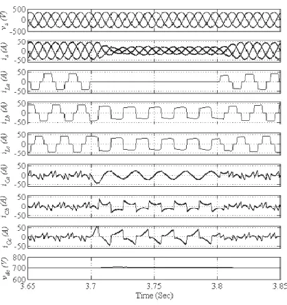
The dynamic performance of a VSC-based DSTATCOM is studied for PFC mode at nonlinear loads. The performance indices are the phase voltages at PCC (Vs), balanced source
currents (
i
s), load currents (i
La,
i
Lb,
i
Lc), compensator currents(
i
Ca,
i
Cb,
i
Cc), and dc bus voltage (v
dc) which are shown in Fig.3 under varying load (at t = 3.7 to 3.8 s) conditions.
B. Performance of DSTATCOM in ZVR Mode
In ZVR mode, the amplitude of the PCC voltage is regulated to the reference amplitude by injecting extra leading reactive power components. The dynamic performance of DSTATCOM in terms of PCC phase voltages (Vs), balanced source currents, load currents , compensator currents, amplitude of voltages at PCC , and dc bus voltage waveforms is shown in Fig. 5 under unbalanced load at a time duration of t = 3.7 to 3.8 s.
IV. EXPERIMENTALRESULTS
[image:5.612.62.271.345.567.2]A prototype of the VSC-based DSTATCOM is developed to validate the proposed control algorithm. ABB make current sensors (EL50P1 BB) and voltage sensors (EM010 BB) are used for sensing the PCC voltages, dc bus voltage, and current signals. The BP training-based control algorithm is used for the control of DSTATCOM using a TMS320F240 digital signal processor. A Fluke (43B) power analyzer and an Ailment make digital oscilloscope (DSO-6014A) are used for the recording of steady state and dynamic state test results, respectively, on a developed DSTATCOM at nonlinear loads. Hardware implementation data are given in Appendix B.
Fig. 4. Dynamic performance of DSTATCOM under varying nonlinear loads in ZVR mode.
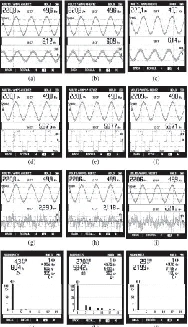
A. Performance of DSTATCOM at Nonlinear Loads
Fig. 5(a)–(i) shows the waveform of the phase “a” PCC voltage (vab) with source currents (isa, isb, and isc), load currents (iLa, iLb, and iLc), and compensating current (iCa, iCb,
and iCc) under nonlinear loads. In Fig. 5(j)–(l), the harmonic distortions of the “a” phase source current, load current, and PCC voltage are observed to be 4.3%, 27.0%,and 2.9%, respectively. These results show satisfactory performance of the BP control algorithm for harmonic elimination according to the IEEE-519 guidelines on the order of less than 5%.
V. CONCLUSION
[image:6.612.77.265.193.520.2]A VSC-based DSTATCOM has been accepted as the most preferred solution for power quality improvement as PFC and to maintain rated PCC voltage. A three phase DSTATCOM has been implemented for the compensation of nonlinear loads us a BPT control algorithm to verify its effectiveness. The proposed BPT control algorithm has been used for the extraction of reference source currents to generate the switching pulses for IGBTs of the VSC of DSTATCOM. Various functions voltage of the DSTATCOM has also been regulated to the rated value
Fig. 5. Performance of DSTATCOM under nonlinear loads: (a-c) isa, isb,m and isc with vab; (d-f) iLa, iLb, and iLc; and (g-i) iCa, iCb, and iCc. (j-l) Harmonic spectra of isa, iLa, and
vab.
without any overshoot or undershoot during load variation. Large training time in the application of the complex system and the selection of the number of hidden layers in the system are the disadvantages of this algorithm. of DSTATCOM such as harmonic elimination and load balancing have been demonstrated in PFC and ZVR modes with dc voltage regulation of DSTATCOM. From the simulation and implementation results, it is concluded that DSTATCOM and its control algorithm have been found suitable for the compensation of nonlinear loads. The dc bus voltage of the DSTATCOM has also been regulated to the rated value without any overshoot or
number of hidden layers in the system are the disadvantages of this algorithm.
REFERENCES
[1] R. C. Dugan, M. F. McGranaghan, and H. W. Beaty, Electric Power Systems Quality, 2nd ed. New York, NY, USA: McGraw-Hill, 2006. [2] A. Ortiz, C. Gherasim, M. Manana, C. J. Renedo, L. I. Eguiluz, and R. J. M.
Belmans, “Total harmonic distortion decomposition depending on distortion origin,” IEEE Trans. Power Del., vol. 20, no. 4, pp. 2651–2656, Oct. 2005. [3] T. L. Lee and S. H. Hu, “Discrete frequency-tuning active filter to suppress
harmonic resonances of closed-loop distribution power systems,” IEEETrans. Power Electron., vol. 26, no. 1, pp. 137–148, Jan. 2011. IEEE TRANSACTIONS ON INDUSTRIAL ELECTRONICS, VOL. 61, NO. 3, MARCH 2014
[4] K. R. Padiyar, FACTS Controllers in Power Transmission and Distribution.New Delhi, India: New Age Int., 2008.
[5] IEEE Recommended Practices and Requirement for Harmonic Control on Electric Power System, IEEE Std.519, 1992.
[6] T.-L. Lee, S.-H. Hu, and Y.-H. Chan, “DSTATCOM with positive sequence admittance and negative-sequence conductance to mitigate voltage fluctuations in high-level penetration of distributed generation systems,” IEEE Trans. Ind. Electron., vol. 60, no. 4, pp. 1417–1428, Apr. 2013. [7] B. Singh, P. Jayaprakash, and D. P. Kothari, “Power factor correction and
power quality improvement in the distribution system,” Elect. India Mag., pp. 40–48, Apr. 2008.
[8] J.-C. Wu, H. L. Jou, Y. T. Feng, W. P. Hsu, M. S. Huang, and W. J. Hou, “Novel circuit topology for three-phase active power filter,” IEEE Trans. Power Del., vol. 22, no. 1, pp. 444–449, Jan. 2007.
[9] Z. Yao and L. Xiao, “Control of single-phase grid-connected inverters with nonlinear loads,” IEEE Trans. Ind. Electron., vol. 60, no. 4, pp. 1384– 1389, Apr. 2013.
[10] A. A. Heris, E. Babaei, and S. H. Hosseini, “A new shunt active power filter based on indirect matrix converter,” in Proc. 20th Iranian Conf. Elect. Eng., 2012, pp. 581–586.
[11] M. Sadeghi, A. Nazarloo, S. H. Hosseini, and E. Babaei, “A new DSTATCOM topology based on stacked multicell converter,” in Proc. 2nd Power Electron., Drive Syst. Technol. Conf., 2011, pp. 205–210.
[12] G. Benysek and M. Pasko, Power Theories for Improved Power Quality. London, U.K.: Springer-Verlag, 2012.
[13] B. Singh and J. Solanki, “A comparison of control algorithms for DSTATCOM,” IEEE Trans. Ind. Electron., vol. 56, no. 7, pp. 2738–2745, Jul. 2009.
[14] C. H. da Silva, R. R. Pereira, L. E. B. da Silva, G. Lambert-Torres, B. K. Bose, and S. U. Ahn, “A digital PLL scheme for three-phase system using modified synchronous reference frame,” IEEE Trans. Ind. Electron., vol. 57, no. 11, pp. 3814–3821, Nov. 2010.
[15] S. Rahmani, A. Hamadi, and K. Al-Haddad, “A Lyapunov-function-based control for a three-phase shunt hybrid active filter,” IEEE Trans. Ind. Electron., vol. 59, no. 3, pp. 1418–1429, Mar. 2012.
[16] S. Rahmani, N. Mendalek, and K. Al-Haddad, “Experimental design of a nonlinear control technique for three-phase shunt active power filter,” IEEE Trans. Ind. Electron., vol. 57, no. 10, pp. 3364–3375, Oct. 2010.
[17] S. N. Sivanandam and S. N. Deepa, Principle of Soft Computing. New Delhi, India: Wiley India Ltd., 2010.
[18] J. S. R. Jang, C. T. Sun, and E. Mizutani, Neuro Fuzzy and Soft Computing: A Computational Approach to Learning and Machine Intelligence. Delhi, India: Pearson Educ. Asia, 2008.
[19] P. Kumar and A. Mahajan, “Soft computing techniques for the control of an active power filter,” IEEE Trans. Power Del., vol. 24, no. 1, pp. 452–461, Jan. 2009
AUTHORS
First Author – Vasanthavalli.C , Post-Graduate scholar, Department of Power Electronics And Drives , SCAD College Of Engineering and Technology , Tirunelveli. Email address – [email protected]