SINGLE IMAGE DE-HAZE UNDER NON-UNIFORM
ILLUMINATION USING BRIGHT CHANNEL PRIOR
1XUEYANG FU, 1QIN LIN, 1WEI GUO, 2XINGHAO DING, 3YUE HUANG
1Department of Communication Engineering, Xiamen University, Xiamen, China 2
Prof., Department of Communication Engineering, Xiamen University, Xiamen, China 3
Asstt Prof., Department of Communication Engineering, Xiamen University, Xiamen, China
E-mail: [email protected]
ABSTRACT
Recent single image de-haze approaches assume the atmospheric light is the only illumination in one haze image and use a globally constant to image de-haze. However, every local pixels in an outdoor image is actually under the influence of non-uniform illumination in real world. The accuracy of the environmental illumination estimation has a great influence on the result, so the traditional haze image model is defective and not conforms to the facts. In this paper, we refine the haze image model under the consideration of non-uniform illumination, and then we propose a new prior called “bright channel prior” to de-haze single image combining with the dark channel prior. The bright channel prior, which inspired by the dark channel prior [1], is a statistic of haze-free outdoor images. Using this prior, we derive a more accurate environmental illumination estimating algorithm for single image de-haze. Our experiments prove the feasibility of the method we propose and outperform other image haze removal approaches.
Keywords: Non-Uniform Illumination, Haze Image Model, Bright Channel Prior, Single Image De-haze
1. INTRODUCTION
How to de-haze effectively has become a hot spot in recent years and made significant progresses. There are many existing image dehazing algorithms based on the dichromatic atmospheric scattering model [2]. Fattal [3] estimates the albedo of the scene and the medium transmission based on the assumption that the transmission and the surface shading are locally uncorrelated. This approach may fail if the assumption is invalid. Tarel’s approach [5] uses combinations of min, max, and median filters to enforce piecewise constant, and use the estimate to obtain a contrast enhanced image of the scene. But his approach only achieved satisfied result on very low saturated scenes. Tan’s approach [4] was maximizing the local contrast of the restored image to receive a de-haze image. He solved the optimization problem by using median filter. However, median filter cannot preserve edge effectively and his results existing halos in the region of texture and angles. K.He [1] proposed the dark channel prior to estimate the transmission and using soft matting to obtain a good result. All
approaches mentioned above have a common point that they assume the airlight radiance is a unique and uniform illumination in one image. However, an outdoor image is actually under multiple and non-uniform illumination [11], and the accuracy of the environmental illumination estimation has a great influence on the de-haze result. So it is too restrictive to use only one globally constant as the illumination.
high quality of de-haze image. Our contribution in this paper is the good performance on the recovery of color, clarity and contrast by eliminating the influence of the environmental illumination.
This paper is organized as follows: In section 2, we first review the traditional haze image model, and then refine the model for non-uniform illumination. In section 3 we present the new prior called “bright channel prior” and prove its existence with experiments. In section 4 we use both bright channel prior and dark channel prior to de-haze image. Experiment results are described in section 5, and the work is concluded in section 6. Section 7 is the acknowledge.
2. REFINING HAZE IMAGE MODEL FOR
NON-UNIFORM ILLUMINATION
The traditional haze image model which widely used in many image de-haze approaches is called the dichromatic atmospheric scattering model [2]. This model is a linear combination of attenuation
s
L and airlight La:
(1 )
s a
d d
I L L
L∞
ρ
e−β L∞ e−β= +
= + − (1)
where I is the observed image; β is the attenuation coefficient and can be seen as a constant;
d
e
−β is also known as the transmission widely described in most image dehazing approaches; L∞is the airlight radiance; ρ and d are the scene albedo and depth at the scene point. The goal in image dehazing is hope to directly estimate the true scene albedo ρ.
Although equation (1) is popular for its simplicity and has been applied in many dehazing approaches, it is still not accurate enough and many qualitative effects are missing. In most image dehazing algorithms, they regard L∞ρ as the final
goal and consider the airlight is a constant in one image. It is obviously not conform to reality. In the daytime, objects are actually under non-uniform illumination. For instance, the reflected light by other objects surface, lamplight and atmospheric particles scattered light can be regarded as different illuminations affect the scene point. In this section, we will take the non-uniform illumination into consideration and refine the haze image model.
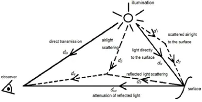
Figure 1 illustrates other three important visual effects due to light transport in scattering media besides the attenuation and airlight in traditional
[image:2.612.313.521.198.303.2]model. Firstly, light can travels in a straight line to the observer. Secondly, airlight also scatters to the surface and gets reflected, leading to effects such as brightening of darker regions. Thirdly, reflected light also scatters to the observer. This model assumes that the single scattering is a common approximation in volumetric scattering and can be used in haze condition.
Figure 1. Three Important Visual Effects When Light Travels To The Observer Through The Scattering
Medium.
An objects color values may vary under non-uniform illumination. So we add non-non-uniform illumination to equation (1), and the directly transmission of the light can be ignored for the scattering of particles in haze weather. According to Figure 1, the attenuation Ls and airlight La are refined as:
1
2
5 3
4 4
2 2
1
2 2
5 3
(1 )
(1 ) (1 )
ls
so
d d
d d
l l
s ls
d d
d d
l r
a
L e L e
L e e
d d
L e L e
L e e
d d
β β
β β
β β
β β
ρ
− −
− −
− −
− −
= + −
= − + −
(2)
where Ll is the radiance of the illumination; Lris
the radiance of the reflected light; dls is the depth
between the illumination and the surface; dsois the
depth between the surface and the observer; d1 is the depth between the illumination and the airlight
scattering point; d2 is the depth between the
airlight scattering point and the surface; d3 is the depth between the surface and the observed light scattering point; d4 is the depth between the
observed light scattering point and the observer; d5 is the depth between the observed light scattering point and the illumination.
[image:2.612.327.526.437.493.2]attenuation and the airlight is also approximately equal in local pixels. For convenience, we denote
e
L represents the environmental illumination. Our final refining haze image model is:
(1
)
s a
e e
I
L
L
L t
ρ
L
t
=
+
=
+
−
(3) where
t
is the new transmission called local transmission since the value is related to the environmental illumination in our method.Equation (2) and (3) is more accurate and close to the objective fact for the consideration of non-uniform illumination. However, it is unrealistic to estimate the illumination image Le directly with only one image. It is an ill-posed problem to solve three unknowns by one equation. In next section, we will propose a new prior called bright channel prior to solve these problems.
3. THE BRIGHT CHANNEL PRIOR
The bright channel prior we proposed is inspired by K.He’s dark channel prior [1]. In his paper, he considered that in most of the non-sky patches, at least one color channel has very low intensity at some pixels in a haze-free outdoor image. In other words, the pixels intensities in these patches will tend to 0 after a minimum filtering. The formula is:
( , , ) ( )
( )
min ( min
( ))
dark C R G B y x CJ
J
∈ ∈Ω
=
x
y
(4)
where J is the haze-free outdoor image; Jc is a color channel of J; Ω( )x is local patch centered at
x
; Jdark is the dark channel of J.According to this prior, we generate an idea that an opposite prior of haze-free outdoor images should be existence and applicable. We call this opposite prior the bright channel prior. Through observing haze-free outdoors images, we find that in the most local patches which not covered by dark objects in haze-free outdoor images include some pixels have high intensity values in one color channel of the RGB. If we normalize these high values, they will tend to 1. The formula of bright channel is:
( , , ) ( )
( )
max ( max
( ))
bright C
C R G B y x
J
J
∈ ∈Ω
=
x
y
(5)
the symbols are the same meaning as equation (4).
We call Jbright the bright channel ofJ.
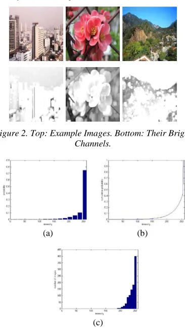
We choose 1000 haze-free outdoor images from
[image:3.612.326.509.306.633.2]internet to demonstrate our idea is feasibility. The images we select include street scenes, cityscape scenes, landscape scenes, buildings and close shot images of flora and fauna. We delete the dark objects areas and use maximum filtering with a patch size 30
×
30. Several haze-free outdoor images and their bright channels are shown in Figure 2.From the results, we can observe that all the outdoor images in bright channels become more whitely. It means that most of the intensities are almost tend to 255 or equal to 255 after a maximum filtering operation. Figure 3(a) is the intensity histogram over all 1000 bright channels and Figure 3(b) is the corresponding cumulative histogram. We can see that about 90% of the pixels have high values above 240. Figure 3(c) is the average intensity of each bright channel.
Figure 2. Top: Example Images. Bottom: Their Bright Channels.
(a) (b)
[image:3.612.333.506.313.427.2](c)
Figure 3. Statistics Of The Bright Channel. (A) Histogram Of The Intensity Of The Pixels In All Of The
Bright Channels (Each Bin Stands For 16 Intensity Levels). (B) Corresponding Cumulative Distribution. (C)
Histogram Of The Average Intensity Of Each Bright Channel.
a conclusion that the high intensities of the bright channel mainly from the sky, white objects and surfaces of colorful objects. Since the intensities of the sky and white objects are always high. The surface of colorful objects has a good reflectance, so the light intensity from the reflection is also high. Our experiments verify the correctness of the bright channel prior convincingly. In next section we will use both bright channel prior and dark channel prior to estimate non-uniform environmental illumination and eliminate the influence of both haze and environmental illumination in single haze image.
4. IMAGE DE-HAZE USING PROPOSED
PRIOR
In this section, we will utilize the bright channel prior and dark channel prior to estimate every local pixels’ non-uniform environmental illumination and the local transmission. In the above section, we have mentioned that in a haze-free outdoor image, the pixels intensity is equal to 0 in dark channel and equal to 1 in bright channel after normalization. The
environmental illumination Le and the local transmission
t
can be seen as piecewise constant in a local patch [14]. So we rewrite equation (3) in an ideally situation.In dark channel,
ρ
dark( , )x y =0:( , )
( , ) ( , ) ( , ) ( , )(1 ( , ))
( , )(1 ( , ))
dark
e dark e
e
I x y
L x y x y t x y L x y t x y
L x y t x y
ρ
= + −
= −
(6)
In bright channel,
ρ
bright( , ) 1x y = :( , )
( , ) ( , ) ( , ) ( , )(1 ( , ))
( , )
bright
e bright e
e
I x y
L x y x y t x y L x y t x y
L x y ρ
= + −
=
(7)
where
( , )
x y
is the current pixel’s coordinate;dark
I
andI
bright are the dark channel and the bright channel of a haze image.Through experiments, we demonstrate that both
the dark channel and the bright channel can exist in one haze image. According to the method of Retinex [12], the illumination should have the property of smooth, so we increase the patch size of the maximum filtering to 61
×
61 in this paper. We set the patch size of the minimum filtering as 15×
15. A filtering operation called guided filter [8] which proposed by K.He is used to preserve the edge and refine both dark channel and bright channel. The result is shown in Figure 4.It is easy to solve out Le and
t
according to equation (6) and (7), the solution is:( , )
( , )
e bright
L x y
=
I
x y
(8)( , )
( , ) 1
( , )
dark
e
I
x y
t x y
L x y
= −
(9)Equation (8) and (9) is the estimation of environmental illumination and local transmission.
We use equation (3) to reconstruct the haze-free image combining equation (8) and (9), the solution is:
0
( , ) ( , ) ( , ) 1
( , ) max( ( , ), ) e
e
I x y L x y x y
L x y t x y t
ρ = + −
(10)
where
t
0 is a lower bound to avoidt
close to zeroand a typical value is 0.1. Equation (10) is the final result of every pixel in the de-haze image.
(a) (b)
[image:4.612.312.520.335.660.2](c)
Figure 4. Results Of Both Refined Dark Channel And Bright Channel. (A) Original Haze Image. (B) The Dark
5. EXPERIMENTAL RESULTS
In our experiments, we process the original haze images by MATLAB R2010b on a PC with a 2.60GHz Intel Pentium Dual Core Processor.
Figure 5 shows our de-haze results. In the results, our proposed approach eliminates the influence of environmental illumination, so the recovery of color and contrast has a significant improvement. The restoration of clarity is also promoted since our local transmission is related to the environmental illumination and includes more detail information.
Figure 6 and Figure 7 show the comparison of our de-haze results with Tarel’s [5] and K.He’s [1]. As can be seen, all the recovery of the color, clarity and contrast in our results outperform the others. The advantage of proposed approach is especially apparent in the long shot and dark region. While in these regions, both Tarel’s and K.He’s results are dark and cannot see objects clearly. As shown in Figure 6, the color of the tree and the carriage in the distance is not clear in Tarel’s and K.He’s results. While in our results, the recovery of these regions
[image:5.612.313.521.73.265.2]
Figure 5. De-Haze Results. Top: Original Haze Images. Bottom: De-Haze Images.
improves markedly. Moreover, our method can also reduce the influence of the halo which produced by some bright light sources, such as the light of the train’s lamp shown in Figure 6.
(a) (b)
(c) (d)
Figure 6. Comparison Of The Result Of “Train”. (A) Original Haze Images. (B) Tarel’s Approach. (C) K.He’s
Approach. (D) The Proposed Approach.
(a) (b)
[image:5.612.315.522.303.484.2]
(c) (d)
Figure 7. Comparison Of The Result Of “Road”. (A) Original Haze Images. (B) Tarel’s Approach. (C) K.He’s
Approach. (D) The Proposed Approach.
Furthermore, we use the contrast of the image as an objective evaluation to verify the result by our approach has a great improvement. The contrast can be expressed as:
1
1
( )
( )
( )
( )
n
i
max i - min i
C
n
=max i + min i
=
∑
(11) where C is the average of contrast in every 3
×
3 non-overlapping patch;max i
( )
is the highest grayvalue in the current patch,
min i
( )
is the lowest [image:5.612.91.297.375.596.2]significant advantage in the contrast of de-haze results by our method.
Table 1: The contrast of different results in Figure 7
Contrast Original
image
Tarel’s result
K.He’s result
Our result
Train 0.0560 0.1513 0.1744 0.2906
Road 0.0652 0.1328 0.1777 0.2641
6. CONCLUSION
In this paper, we refine the haze image model and propose a new prior which called bright channel prior to remove haze in image. The advantage of our method is estimating every local pixels non-uniform illumination and local transmission. The recovery of the color, clarify and contrast improves significantly.
Since our proposed prior is inspired by the dark channel prior, it has a few similar limitations as [1]. In some particular regions, such as the sky or large areas of dark objects, may have a little over–enhancement. We leave these problems for further research.
7. ACKNOWLEDGE
The work is supported by National Natural Scien ce Funding of China, NO. 61172179, 30900328 and Fundamental Research Funds for the Central Unive rsities 2011121051, the Natural Science Foundation of Fujian Province of China 2012J05160.
REFERENCES:
[1] Kaiming He, Jian Sun, Xiaoou Tang, “Signal Image Haze Removal Using Dark Channel Prior”,
IEEE Conference on Computer Vision and Pattern Recognition, 2009, pp. 1956-1963. [2] Srinivasa G. Narasimhan, Shree K, “NayarVision
and Atmosphere”, International Journal of Computer Vision, Vol. 48, No. 3, 2002, pp. 233-254.
[3] R.Fattal, “Single image de-hazing”, ACM Transactions on Graphics, Vol. 27, No. 3, 2008, pp.1-9.
[4] Robby T. Tan, “Visibility in Bad Weather from a Single Image”, IEEE Conference on Computer Vision and Pattern Recognition, 2008, pp. 1-8. [5] J.P. Tarel and N. Hauti‘ere, “Fast Visibility
Restoration from a Single Color or Gray Level Image”, IEEE International Conference on Computer Vision, 2009.
[6] Arjan Gijsenij, Rui Lu and Theo Gevers, “Color Constancy for Multiple Light Sources”, IEEE Transactions on Image Processing, Vol. 21, No.
2, February 2012.
[7] Srinivasa G. Narasimhan, Shree K. Nayar, “Contrast Restoration of Weather Degraded Images”, IEEE Transactions on Pattern Analysis and Machine Intelligence, Vol. 25, No. 6, 2003, pp. 713-724.
[8] Kaiming He, Jian Sun, and Xiaoou Tang, “Guided Image Filtering”, The 11th European Conference on Computer Vision ,2010.
[9] McCartney, E, “Optics of the atmosphere: scattering by molecules and particles”, New York: Wiley, 1975.
[10] Middleton, W, “Vision through the atmosphere”, Toronto: University of Toronto Press,1952 [11] Sun, B., Ramamoorthi, R., Narasimhan, S. G.,
and Nayar, S. K, “A Practical Analytic Single Scattering Model for Real Time Rendering”,
ACM Transactions on Graphics, Vol. 24, No. 3 2005, pp. 1040-1049.
[12] Kimmel R, Elad M, Shaked D, et al, “A Variational Framework for Retinex”,
International Journal of Computer Vision, Vol. 52, No. 1, 2003, pp. 7-23.
[13] Srinivasa G. Narasimhan and Shree K. Nayar., “Chromatic Framework for Vision in Bad Weather”, IEEE Conference on Computer Vision and Pattern Recognition, 2000, pp. 598-605.
[14] Kimmel R, Elad M, Shaked D, et al, “Bayesian Defogging”, International journal of computer vision, Vol. 98 ,2012, pp. 263-278.