Processors
Control Data 2551 Network Processing Unit
The entry level 2551-1 represents the standard Control Data communications processor. The main cabinet, shown above, includes processor with a minimum of 64K bytes of main memory, power supply, and a loop multiplexer with a capability of terminating up to 32 communications lines.
MANAGEMENT SUMMARY
Both communications processors in this family are based
on the same microprocessor and can accommodate
synchronous communication lines up to 56,000 bps and
asynchronous communication lines up to 9600 bps. All
lines can be full- or half-duplex. A 2551 interfaces with
Control Data's CYBER 170, CYBER 70, and 6000 Series
host computer systems.
The basic 2551-1 includes 32K words (I6-bit words) of
memory expandable to 128K words. One Loop
Multi-plexer is standard and will support up to 32
communica-tions lines. The 2551-1 communicacommunica-tions processor can
service a data flow of up to 10,000 characters per second
regardless of the number of lines.
Two programmable front-end processors for CDC's CYBER 70. CYBER 170. and 6000 Series computers. either of which could also be configured as remote communications concentrators.
The 2551-1 supports attachment of 32 communications lines; the 2551-2 can be expanded to accommodate the attachment of up to 254 lines. Both contain 64K bytes of memory. expandable to 256K bytes. Syn-chronous lines are supported. half- or full-duplex. at up to 56K bps. Async lines are likewise supported to 9600 bps.
A basic 2551-1 with 32 communications lines rents for $2.600 per month. which includes maintenance. or can be purchased for $60.000.
CHARACTERISTICS
VENDOR: Control Data Corporation, 8100 34th Avenue South, Minneapolis, Minnesota 55440. Telephone (612) 853-8100.
DATE OF ANNOUNCEMENT: April 1974.
DATE OF FIRST DELIVERY: 2550-2-September 1975; 2551-1 and 2551-2-November 1977.
NUMBER DELIVERED TO DATE: 800 (all models). SERVICED BY: Control Data Corporation.
CONFIGURATION
The 2551 Network Processing Unit is a 16-bit micro-processor with a 168-nanosecond micro-cycle time and a 550-nanosecond main memory cycle time. Currently, two models are available; the 2551-1 and the 2551-2. The 2551-1 can service 10,000 characters per second from a maximum of 32 communications lines; the 2551-2 model can service 10,000 characters per second from a maximum of 254 lines. Both models interface with Control Data's CYBER 170, CYBER 70, and 6000 Series host computer systems. Both can be configured as front-ends or remote concentrators. A 2551 implemented as a remote concentrator requires a system autostart module, which includes a cassette tape unit that loads the remote system. The remote 2551 is connected to the 2551 front-end local to the host via a single high-speed HDLC link. An additional software load, the Link Interface Program, is required in both the local and the remote end when a remote 2551 is attached.
The basic 2551-2 has 32K-word memory which can be
Common to both available models are: 32K words of 16-bitexpanded to 128K words. Two 32-line Loop Multiplexers
MOS main memory (i.e. 64K bytes), one Channel Couplerare standard, and with the addition of up to six more
for attachment to the host computer, Loop Multiplexer(s)Loop Multiplexers, the processor can support up to 254
that accommodates 1 to 32 communication lines each (thelines. Despite the increased line attachment capacity, the
2551-1 has one, and the 2551-2 has two, as standard equipment), a programmable Cyclic Encoder, consolemaximum processor throughput is still limited to about
attachment interface, and a maintenance panel and10,000 characters per second. Both 2551 models can serve
I>
maintenance cassette drive. The models differ in their ~C13-263-102
Processors
Control Data 2551 Network Processing Unit
as remote communications concentrators, connected -loa
local 2551 via a high-speed HDLC link.
The Communications Control program (CCP) is the
software package operative in the 2551. CCP's major
elements are the Base System Software, tire Host
Interface Program, and the Terminal Interface Program.
CCP will interface with NOS and
NOSI
BE (with
Intercom) in the host computer. PASCAL, which is
similar to ALGOL, is the compiler language for user
programming of the Communications Processor.
The latest version of CCP, Version 3.1, supports the 2551
as either a front.:end or a remote concentrator in a
single-host environment or in a multi-single-host/multi-communica-
multi-host/multi-communica-tions processor networking environment. CDC has also
recently released a no-charge enhancement to the CCP
that allows the 2551 to operate as a certified X.25 gateway
to GTE Telenet's public packet-switching network. CDC
has stated that they plan to obtain certification to
Tymshare, France's Transpac, and Canada's Datapac as
well.
The 2551 models are essentially an upward migration
from two predecessor models; the 2550 and 2552. The
same hardware configuration is used, but functionality
via software has been enhanced. In addition to the remote
configurability of the 2551, HDLC protocol support has
been added, which provides for high-speed bit-oriented
synchronous transmission. The HDLC capability permits
support of the X.25 packet protocol.
Control Data has a corporate policy of not providing lists
of users names to the public, and we were unable to locate
a sufficient number of users among our subscribers to
provide a meaningful analysis of user experience.
Therefore, no User Reaction section appears in this
report.
0expansion capabilities in that the 2551-2 can be expanded to include additional Loop Multiplexers, and subsequently supports the attachment of more communications lines. Main memory can be expanded in increments of 16K or 32K 16-:bit words, in either model, to a system maximum of 128K words (256K bytes).
By the addition of Loop Multiplexer Line Expansion Units, the 2551-2's communication lines capacity can be expanded in increments of 32 lines. The 2551-2 can be expanded to a capacity of 254 lines via a total of up to eight Loop Multiplexer Line Expansion Units. One or more Expansion Cabinets are required if more than two Loop Multiplexer Line Expansion Units are configured; eacb Expansion Cabinet holds up to two additional Loop Multiplexer Line Expansion Units.
Both models permit a second Channel Coupler to be added for a second attachment to the host processor or for attachment to a second bost processor. When two Channel Couplers are attached to the Communications Processor, only one Channel Coupler can be active at a time. However, the multi-host computer system can achieve considerable fall-back capability. The coupler provides the means for transfers between the CYBER host, or hosts, and the 2551 at high-speed channel rates .. The· host peripheral processing unit initiates all coupler operations. Supervision of the
coupler involves software commands, instructions and control words common to both the host peripheral controller and the 2551.
Under NOS and NOS/BE, networking allows a maximum of eight (under NOS) or twelve (under NOS/BE) 2551 front-ends to be connected to a single CYBER 170 host, with one or two 2551s attached per host channel. Remote 2551s are supported under NOS only, and are connected to local 2551 front-ends via high-speed HDLC links. A maximum of eight remote 2551s can be connected to anyone 2551 front-end, each by a single HOLC link. A remote 2551 can be
connected to a maximum of four 2551 front-ends. The 2551 system will accept any coilsole that conforms with EIA RS-232-C standards, uses ASCII TTY protocol, and operates asynchronous up to 9600 bps.
The 2551-1 is field-upgradeable to 2551-2. To do so requires the installation of the 2580-3 Upgrade Kit.
TRANSMISSION SPECIFICATIONS
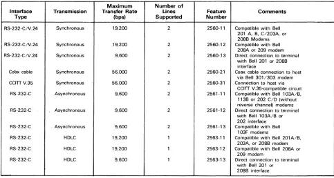
The modems for communication lines are cabled to a Communication Line Adapter (CLA). Direct lines to local terminals are also supported. Each CLA can have two communication lines attached. All of the CLA types available will accommodate full-duplex, half-duplex, or echoplex lines. For asynchronous transmissions of up to 9600 bps, the CLA #2561 Series will support modems or terminals meeting EIA RS-232-C or CCITT V.24 interface standards, and is compatible with AT&T 103, 113, and 202 data sets. Automatic speed recognition is provided for speeds up to 1200 bps. For synchronous transmissions of up to 19.2K bps, the CLA #2560 Series will support modems meeting EIA RS-232-C interface standards, and is compabole with AT&T 201 and 208 data sets. For character-synchronous transmissions of up to 56,000 bps, CLA #2560-21 and #2560-31 will support AT&T 301/303 data sets, and CCITT V.35 (including AT&T digital data facilities) interface standards, respectively. For bit-synchronous transmission of up to 19.2K bps, an HDLC CLA #2563 Series is available with an RS-232-C interface. For more information on CDC's Communications Line Adapters, see Table 1.
PROCESSOR
The hardware and firmware that Control Data employs for moving data between the lines and the Communications Processor's memory is called the Multiplexer Loop Subsystem. Control of this subsystem is performed by the processor's resident software and microprogram.
Up to 16 CLA's can be attached to one Loop Multiplexer, for a maximum total of 32 lines. The Loop Multiplexer serves as the physical and electrical connection of CLA's to the Multiplexer Loop. The Multiplexer Loop can be viewed as two data paths, one inbound and one outbound. All Loop Multiplexers in the system are connected to the Multiplexer Loop, which in turn is attached to the Multiplexer Loop Interface Adapter. The Adapter can place incoming data directly into memory under program control through the Interrupt Data Channel (IDC) interface. Outgoing data likewise uses the IDC interface.
The similarity of names for the attachments in the Mnltiplexer Loop Subsystem is confusing. The following schematic should help while reading the description of data flow through the subsystem.
CLA-Loop - MUltiplexer - Multiplex Processor Multiplexer - - Loop - Loop via IDC
Interface
.
---
·t
--Adapter Memory
t - - - - Multiplexer Loop Subsystem
- - - 1 1
~© 1981 DATAPRO RI;SEARCH CORPORATION. DELRAN •. NJ 08076 .USA REPRODUCTION PROHIBITED
(
Processors
Control Data 2551 Network Processing Unit
TABLE 1. CDC 2551 COMMUNICATIONS LINE ADAPTERS
Maximum Number of Interface Transmission Transfer Rate Lines
Type (bps) Supported
RS-232-CN.24 Synchronous 19,200
RS-232-CN.24 Synchronous 19,200 RS-232-CN.24 Synchronous 9,600
Co"iix cable Synchronous 56,000 CCITTV.35 Synchronous 56,000 RS-232-C Asynchronous 9,600
RS-232-C Asynchronous 9,600
RS-232-C . Asynchronous 9,600 RS-232-C HDLC 19,200 RS-232-C HDLC 19,200 RS-232-C HDLC 9,600
~ Under control of the Communications Processor, outbound data must leave memory via the IDC interface.
Instead of periodically scanning each CLA for incoming traffic, the Multiplexer Loop Interface Adapter (MLIA) periodically sends empty Input Loop Batches around the inbound data path of the Multiplexer Loop. (Actually, what is taking place physically is that the processor transmits to the first CLA on the first Loop Multiplexer which retransmits to the second CLA and so on until all CLA's on the first Loop Multiplexer have been serviced, and then on to the other Loop Multiplexers.) The Loop Batch consists of a series of Loop Cells; each cell consists of 12 bits: 1 start-of-cell bit, 3 bits identifying the type of information contained in the cell (or that the cell is empty), and 8 bits of information. The Loop Batch travels past each Loop Multiplexer and then back to the MLIA. If any CLA has filled its character buffer with incoming data; it will "demand service" of its Loop Multiplexer. The Loop Multiplexer will respond by filling the next three empty Loop Cells. The first cell receives the CLA address, the second cell receives the transmitted information, and the third cell receives error checking information (Cyclic Redundancy Checksum). If, in addition to information, the . CLA has supervisory information to send to the processor, that information would be placed in Loop Cells following the data cell and before the error checking cell.
When the Loop Batch, filled with data from many CLA's, completes its travel around the loop and arrives at the MLIA, error checking is performed by the programmable Cyclic Encoder. The Encoder can be programmed to accommodate most error detecting schemes. If an error is found, error recovery for retransmission is initiated. If the data is acceptable, the MLIA places the data directly into memory through the Direct Memory Access Interface Channel. Control tables, updated by the MLIA, and the operating software indicate where the data is to be stored in memory. If the transmission is complete, the MLIA triggers an interrupt for processor action. It is the return of a Loop Batch to the MLIA that causes the MLIA to initiate another empty Loop Batch around the loop.
2
2 2
2 2 2
2
2 1 1 1
Feature Comments
Number
2560-11 Compatible with Bell 201 A, B, C1203A, or 20BB Modems 2560-12 Compatible with Bell
208A or 209 modem 2560-13 Direct connection to terminal
with Bell 201 or 20BB interface
25tiO-21 Coax cable connection to host via Bell 301/303 modem 2560-31 Connection to host via
CCITT V.35-compatible circuit 2561-11 Compatible with Bell 103A/B, 113B or 202 C/D (without reverse channel) modems 2561-12 Direct connection to terminal
with Bell 103A/B or 202 interface 2561-13 Compatible with Bell
103F modems
2563-11 Compatible with Bell 20lA/B, 203A. or 208B' modem 2563-12 Compatible with Bell 20SA or
209 modem
2563-13 Direct connection to terminal with Bell 201 or
208B interface
Outbound data travels in Loop Batches on the outbound data path. Once a CLA has received the beginning of an outbound transmission, servicing the CLA with the remainder of the transmission is, again, not done by scanning, but by the CLA demanding service, or more data. The MLIA cannot take output data directly from memory but receives it via the Interrupt Data Channel Interface. As on the input side it requires several cells to supply the CLA address, the data, supervisory information, and error checking information. The Loop Batches leaving the MLIA will contain data for many CLAs.
SOFTWARE
The software operative in the 255X Communication Processors is the Communication Control Program (CCP). CCP is composed of three major elements. The first element is called Base System Software and performs the function of an operating system, related utility functions, queue manager, and console support. The second element is called the Host Interface Program and services the interface with the host. This element controls and formats data moving between the Communications Processor's memory and the host computer .. The host's operating system can be either NOS or NOS/BE. The third element is called the Terminal Interface Program (TIP) and accommodates the necessary interface between the' different terminal protocols and the standard internal protocol of the processor. Among the terminal protocols supported are: Teletype, IBM 2741, CDC Mode 4, APL-mode terminals, IBM 2780/3780, IBM HASP Multileaving, and the CCITT X.25 interface. Since CCP is written in a higher level language, PASCAL, other terminal types can be supported by generation of a new TIP, or modification of an existing one. This is accomplished through use of the CYBER Cross System, whic.h executes on a CYBER host. CROSS provides a series of CCP support tools including a PASCAL compiler, macro/micro assembler, link editor, and a library maintenance capability. All of these utilities run on a
CYBER host computer. . .
[image:3.612.62.545.101.359.2]C13-263-104 Processors
Control Data 2551 Netw6rk Processing Unit
Configuration
Main Cabinet
Memory (1) I I Module
~ I
---"T---
JI I ~ 8l I
Communications Console
I I
~~I
Processor 752-10, or I I .-~ c:~ I equiwlent i"'"-- ... ----4~ IMemory (1) I I . Module
I-i " ' " - . - - - L - - r T
--
_..
Host Coupler (2) I I I CLA(4)I
-
-
2558-3 I I ' - - - 1 - - I I I-~
I I I 2556-10 Expansion Cabinet (5)i " ' " - - - I ~
I !:lCll I I
~
!~
I I CLA(4)..
..
Host Coupler (2) I.,
I I I I L I2558-3 I ~ I I Loop
- -- -
-
I-
~:2 I I I I
i " ' " - - - I
2l
I I __ L_ I Multiplexer I I~ Line I I
I I I
~
CLA(4) Expansion I II Remote System (2) I I
__ 1
Unit 1 ___ L __-
-
-
--Autostart Module I c. I J I I
~
CLA(4) CLA(4)I I I
- - - - -1- - - i - -
---1
~
Ir-'--
II I I CLA(4)
Maintenance I CIl I ~ I
%1
§:~
I I Loop,-
---
IPanel I I I I
I '3 I
!~
I I I Multiplexer I- - - -
:2I I Line I I I
-1 I :2 I Expansion
I I
I I
Maintenance I I I I Unit I ___ L __ Cassette I I j - - ' - -CLA(4) I I I
CLA(4)
I I I I
I
I
(1) Memory Modules available in 32K-byte or 64K-byte increments, up to a system maximum of 256K bytes, including main memory.
(2) One Host Coupler basic to system; one additional may be implemented. If system is used as remote concentrator, would require Autostart Module instead of Host Coupler(s).
(3) 2551-1 supports only one Loop Multiplexer. 2551-2 may support up to eight, but only two are resident in main cabinet.
(4) Up to 16 Communication Line Adapters (CLA) can be implemented per Loop Multiplexer or Expansion Line Unit. Each CLA supports up to two lines. (5) Applicable only to 2551-2 systems. Each expansion cabinet supports up to two Loop Multiplexer Line Expansion Units.
~ The Base System Software handles the internal operation of the communications processor. Included are: a system nionitor, which controls allocation of the programs running in the processor; an interrupt handler, which controls the transition of the processor between different program-interrupt levels; a console utility, which processes service messages such as commands, alarms, reports and diagnostic information received from the local console; buffer maintenance and queue utilities, which dynamically allocate memory in varying buffer sizes and provide for the queuing and dequeuing of data buffers; and debug and diagnostic utilities, which permit system dumping during program development or system failures and isolation of communica-tions line problems.
Diagnostics are performed on-line, and are initiated by supervisory commands from the network operator. Base System Software also allows for date and time stamping services, and basic message processing which includes code conversion, insertion, CRC/LRC generation and character counting.
The Host Interface and Terminal Interface Programs are part of the interface software which includes processor support of virtual terminal connections in conjunction with CYBER host network products. The 2551 cooperates with the host in establishing a link with certain interactive and batch terminal stations wherein, once the link is
established, the physical characteristics of the source terminal are transparent to the host.
CDC has also added a Line Interface Program which controls information transfer between a local and remote 2551. Such links utilize the Control Data Corporation Control Procedure (CDCCP), which is CDC's bit-synchronous version of ISO's HDLC standard. Other CCP software modules are collectively grouped as the Network Control Software, which define the processor's role in relation to the network. These modules perform functions which include network routing, statistical reporting, and processing of service messages.
PRICING
The 255X Communications Processors can be purchased or leased either directly or through Control Data's Commercial Credit subsidiary. When leasing directly, only a one-year lease agreement is available. At the end of the year, unless other action is taken, the equipment will automatically be on a 90-day notice agreement. Credit towards purchasing the equipment is part of the one-Year agreement; 30 percent of the first year's rental can be applied as a credit toward the purchase price, 45 percent of the second year's rental, 60 percent of the third year's rental, and 75 percent Qf all subsequent rentals. From Commercial Credit, a three-year lease agreement is available. It is non-cancellable for 24 months and its term is non-extendable. Five-year arrangements are also available through Commercial Credit. ~
© 1981 DATAPRO RESEARCH CORPORATION, DELRAN, NJ 08075 USA REPRODUCTION PROHIBITED
(
(
"k.(
Control Data 2551 Network Processing Unit
Monthly Rental* 1-Year 3-Year
~ 2551-1 Network Processing Unit $1.205 $1,184 2551-2 Network Processing Unit 1,527 1.499 2580-3 2551-1 to 2551-2 Upgrade Kit 327 321 2554-16 MOS Memory Expansion, 16,384 words 204 200 2554-32 MOS Memory Expansion, 37,768 words 391 384 2556-10 Expansion Cabinet 181 178 2556-11 loop Multiplexer line Expansion Unit 152 149 2558-3 Host Computer Coupler 138 136 2580-4 Remote System Autostart Module/Cassette Unit 63 62 2560-11 CLA; sync; RS-232-C; 201/8B-compatible 43 42 2560-12 CLA; sync; RS-232-C; 203A/9-compatible 43 42 2560-13 CLA; sync; RS-232-C; direct connection to terminal 43 42 2560-21 CLA; sync; coax; 301/303-compatible 62 61 2560-31 CLA; sync; V.35 43 42 2561-11 CLA; async; RS-232-C; 203-compatible 36 35 2561-12 CLA; async; RS-232-C; direct connection to terminal 36 35 2561-13 CLA; async; RS-232-C; 103F-compatible 36 35 2563-11 CLA; SOlC; RS-232-C; 201/8B-compatible 49 48 2563-12 CLA; SOlC; RS-232-C; 208A-compatible 49 48 2563-13 CLA; SOlC; RS-232-C; direct connection to terminal 49 48
Initial Monthly
Software Fee Charge*
-N221-01 CCP 3; for NOS host $570 $125 N221-02 link Interface Program; for remote 2551 120 50 N222-01 CCI; for NOS/BE host 570 125 'Includes maintenance .•
SEPTEMBER 1981 © 1981 DATAPRO RESEARCH CORPORATION, DELRAN, NJ 08075 USA REPRODUCTION PROHIBITED
Purchase
$33.400 43.400 10,000 5,500 9,920 6,000 4,029 3,938 1,500 997 997 997 1,553 997 785 785 785 925 925 925
Paid Up License
$3,370 1,320 3,370
Processors
Monthly Maintenance
$318 366 53 48 96 27 32 39 21
Processors
Control Data 2551 Network Processing Unit
The entry level 2551-1 represents the standard Control Data communications processor. The main cabinet, shown above, in-cludes processor with a minimum of 64K bytes of main memory, power supply, and a loop multiplexer with a capability ofterminat-ing up to 32 communications lines.
MANAGEMENT SUMMARY
Both communications processors in this family are based
on the same microprocessor and can accommodate
syn-chronous communication lines up to 56,000 bps and
asynchronous communication lines up to 9600 bps. All
lines can be full- or half-duplex. A 2551 interfaces with
Control Data's CYBER 170, CYBER 70, and 6000 series
of host computer systems.
The basic 2551-1 includes 32K (l6-bit words) memory
expandable to 128K. One Loop Multiplexer is standard
and will support up to 32 communication lines. The 2551-1
communications processor can service a data flow of up
to 10,000 characters per second regardless of the number
of lines.
The basic 2551-2 has 32K memory which can be expanded
to 128K. Two 32-line Loop Multiplexers are standard,
and with the addition of Loop Multiplexers, the processor
can support up to 254 lines. Despite the increased line
attachment capacity, the maximum processor throughput
is still limited to about 10,000 characters per second.
Both 2551 models can serve as remote communications
t>
Two programmable front-end processors for CDC's CYBER 70, CYBER 170 and 6000 series computers, either of which could also be configured as remote communications concentrators.
The 2551-1 supports attachment of 32 com-munications lines; the 2551-2 can be expanded to accommodate the attachment of up to 254 lines. Both contain 64K bytes of memory, expandable to 256K bytes. Synchronous lines are supported, half- or full-duplex, at up to 56K bps. Async lines are likewise supported to 9600 bps.
A basic 2551-1 with 32 communications lines rents for $2,300 per month, which includes maintenance, or can be purchased for $74,000.
CHARACTERISTICS
VENDOR: Control Data Corporation, 8100 34th Avenue South, Minneapolis, Minnesota 55440. Telephone (612) 853-8100.
DATE OF ANNOUNCEMENT: April 1974.
DATE OF FIRST DELIVERY: 2550-2-Septemher 1975; 2551-1 and 2551-2-November 1977.
NUMBER DELIVERED TO DATE: 250 (all models). SERVICED BY: Control Data Corporation.
CONFIGURATION
The 2551 Network Processing Unit is a 16-bit microprocessor with a 168-nanosecond micro-cycle time and a 550-nano-second main memory cycle time. Currently, two models are available; the 2551-1 and the 2551-2. The 2551-1 can service 10,000 characters per second from a maximum of 32 com-munications lines; the 2551-2 model can service 10,000 characters per second from a maximum of 254 lines. Both models interface with Control Data's CYBER 170, CYBER 70, and 6000 series of host computer systems. Either processor can support attachment to two hosts, or to one host and another 2551. Both can be configured as remote concen-trators.
A 2551 implemented as a remote concentrator requires a system autostart module; a cassette tape unit which loads the remote system. An additional software load, the Link Interface Program, is required in the host front end when a remote 2551 is attached.
Common to both available models are: 32K MOS main memory, Channel Couplers for attachment to the host computers, a Loop Multiplexer that accommodates 1 to 32 communication lines, a programmable Cyclic Encoder, con-sole attachment interface, and a maintenance panel and maintenance cassette drive. The models differ in their ex-pansion capabilities in that the 2551-2 can be expanded to include additional Loop Multiplexers, and subsequently supports the attachment of more communications lines. ~
C13-263-102 Processors
Control Data 2551 Network Processing Unit
I:>
concentrators, connected to a local 2551 via a high-speed
HDLC link.
The Communication Control Program (CCP) is the
software package operative in the 2551. CCP's major
elements are the Base System Software, the Host
Inter-face Program, and the Terminal InterInter-face Program. CCP
will interface with NOS and NOS/BE (with Intercom)
in the host computer. PASCAL, which is similar to
ALGOL, is the compiler language for user programming
of the Communications Processor.
The latest version of CCP,/Version 3, supports a
com-munications processor as either a front end or as a remote
concentrator in a single host environment. CDC has
stated, however, that a new version, scheduled for release
in the near future, will support a configuration of mUltiple
hosts and mUltiple communications processors in a
net-work environment. This projected configurability might
be compared to IBM's Multisystem Networking Facility,
which was announced in 1976.
The 2551 models are essentially an upward migration
from two predecessor models; the 2550 and 2552. The
same hardware configuration is used, but functionality
via software has been enhanced. In addition to the remote
configurability of the 2551, H DLC protocol support
has been added, which provides for high-speed
bit-oriented synchronous transmission. The H D LC capability
permits Level 2 support of the X.25 packet protocol.
As with the previous 255X models, up to two hosts
can be serviced by, or channel-coupled to, a single 2551.
CDC states that, additionally, up to eight 2551's can be
attached to a single host.
USER REACTION
From the 1977 and 1978 Communications Processors
Survey, Datapro identified four 2551-2 users, each of
whom reported their experience with a single 2551
processor. The number of lines per processor varied
from 10 to 128, with a wide range of speeds and protocols.
One user was interfacing to a CYBER 170; the others
all had Series 6000 hosts. The average time that each
processor had been in operation was 18 months. The
users' ratings are as follows:
Excellent Good Fair
f22r
W A*
Overall satisfaction 2 2 0 0 3.8
Ease of installation 2 I I 0 3.3
Throughput I 3 0 0 3.3
Hardware reliability 2 I I 0 3.3
Promptness of maintenance 4 0 0 0 4.0
Quality of maintenance 3 I 0 0 3.8
Software I 2 I 0 3.0
Technical support 3 I 0 0 3.8
*Weighted Average on a scale of 4.0 for Excellent.
In general, the ratings indicate satisfaction with the 2551.
The high ratings given CDC's maintenance (both prompt-
t>
~ Main memory can be expanded in increments of 16K or 32K 16-bit words, in either model, to a system maximum of 128K words. By the addition of Loop Multiplexers, com-munication line capacity can be expanded in increments of 32 lines. The 2551-2 can be expanded to a capacity of 254 lines via the addition of up to seven Loop Multi-plexers. Both models permit a second Channel Coupler to be added for a second attachment to the host processor or for attachment to a second host processor.
The hardware and firmware that Control Data employs for moving data between the lines and the Communications Processor's memory is called the Multiplexer Loop Subsys-tem. Control of this subsystem is performed by the proc-essor's resident software and microprogram.
TRANSMISSION SPECIFICATIONS
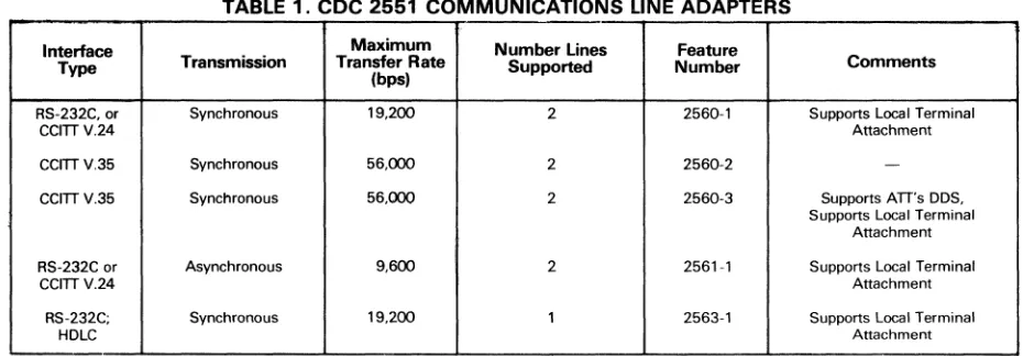
The modems for communication lines are cabled to a Communication Line Adapter (CLA). Each CLA can have two communication lines attached. All five of the CLA types available will accommodate full-duplex or half-duplex lines. For asynchronous transmissions of up to 9600 bps, CLA #2561-1 will support modems meeting EIA RS232C or CCITT V24 interface standards, and is compatible with AT&T 103, 113, and 202 data sets. For synchronous trans-missions of up to 19.2K bps, CLA #2560-1 will support modems meeting EIA RS232C interface standards and is compatible with AT&T 201 and 208 data sets. Both of the above CLA's will support local lines. For character-syn-chronous transmissions of up to 56,000 bps, CLA's #2560-2 and #2560-3 will support AT&T 301/303 data sets, and CCITT V35 (including AT&T digital data facilities) interface standards, respectively. For bit-synchronous transmission of up to 19.2K bps, an HDLC CLA #2563-1 is available with an RS-232C interface.
PROCESSOR
Up to 16 CLA's can be attached to one Loop Multiplexer, for a total of 32 lines. The Loop Multiplexer serves as the physical and electrical connection of CLA's to the Multiplex Loop. The Multiplex Loop can be viewed as two data paths, one inbound and one outbound.
All Loop Multiplexers in the system are connected to the Multiplex Loop, which in turn is attached to the Multiplexer Loop Interface Adapter. The Adapter can place incoming data directly into memory under program control through the Interrupt Data Channel (IDC) interface. Outgoing data likewise uses the IDC interface.
The similarity of names for the attachments in the Multi-plexer Loop Subsystem is confusing. The following sche-matic should help while reading the description of data flow through the subsystem.
CLA-loop --- Multiplexer-Multiplex Processor
Multiplexer -loop Loop via IDC . - - Interface •
Adapter
.
----
Memoryt
--I----Multiplexer loop S u b s y s t e m - - - !
Under control of the Communications Processor, outbound data must leave memory via the IDC interface.
Instead of periodically scanning each CLA for incoming traffic, the Multiplexer Loop Interfaee Adapter (MLlA) periodaically send empty Input Loop Batches around the inbound data path of the Multiplexer Loop. (Actually, what
is taking place physically iI that the processor transmits to the first eLA on the first Loop Multiplexer which retrans-mits to the second CLA and so on until all CLA's on the first
© 1979 DATAPRO RESEARCH CORPORATION, DELRAN, NJ 08075 USA REPRODUCTION PROHIBITED
(
Processors
Control Data 2551 Network Processing Unit
TABLE 1. CDC 2551 COMMUNICATIONS LINE ADAPTERS
Interface Maximum
Type Transmission Transfer Rate (bps)
RS-232C, or Synchronous 19,200 CCITTV.24
CCmV.35 Synchronous 56,000 CCITTV.35 Synchronous 56,000
:
RS-232C or Asynchronous 9,600 CCITTV.24
RS-232C; Synchronous 19,200 HOLC
l:>
ness and quality) and technical support are considerably
above those given by users of similar products from other
major vendors.
Software ranked the lowest of the rated criteria, but still
faired well. CDC has made recent enhancements to both
the CCP and related host software which may not have
been reflected in the ratings used in this survey. Future
ratings may indicate a higher degree of software
satis-faction. There were no significant difficulties reported
with the 2551. One user indicated difficulty with
com-munications lines and modems that was apparently
unrelated to the operation of the 2551.D
~ Loop Multiplexer have been serviced, and then on to the other Loop Multiplexers.) The Loop Batch consists of aser-ies of Loop Cells; each cell consists of 12 bits: 1 start-of-cell bit, 3 bits identifying the type ofinformation contained in tbe cell (or tbat the cell is empty), and 8 bits of information. Tbe Loop Batch traveis past each Loop MUltiplexer and then back to the MLIA. IT any CLA has fdled its character buffer witb incoming data, it wl1I "demand service" of its Loop Multiplexer. The Loop Multiplexer will respond by filling the next three empty Loop CeDs. The first ceD receives the CLA address, the second cell receives the transmitted infor-mation, and the third cell receives error checking informa-tion (Cyclic Redundancy Checksum). IT, in addiinforma-tion to information, the CLA has supervisory information to send to the processor, that information would be placed in Loop Cells following the data cell and before the error checking cell.
When the Loop Batch, fiDed with data from many CLA's, completes it travel around the loop and arrives at tbe MLIA, error cbecking is performed by the programmable Cyclic Encoder. The Encoder can be programmed to accommodate most error detecting schemes. IT an error is found, error recovery for retransmission is initiated. IT the data is accept-able, the MLIA places the data directly into memory through the Direct Memory Access Interface Channel. Control tables, updated by the MLIA, and the operating software indicate where the data is to be stored in memory. IT the transmission is complete, the MLIA triggers an interrupt for processor action. It is the return of a Loop Batch to the MLIA that causes the MLIA to initiate another empty Loop Batch around the loop.
Outbound data travels in Loop Batcbes on the outbound data path. Once a CLA bas received the beginning of an outbound transmission, servicing the CLA with the remain-der oftbe transmission is, again, not done by scanning, but . by the CLA demanding service; or more data. The MLIA
Number Lines Feature
Comments Supported Number
2
2 2
2
1
2560-1 Supports Local Terminal Attachment 2560-2
-2560-3 Supports ATT's DOS, Supports Local Terminal
Attachment 2561-1 Supports Local Terminal
Attachment 2563-1 Supports Local Terminal
Attachment
cannot take output data directly from memory but receives it via the Interrupt Data Channel Interface. As on the input side it requires several cells to supply the CLA address, the data, supervisory information, and error checking informa-tion. The Loop Batches leaving tbe MLIA will contain data for many CLA's.
When two Channel Couplers are attached to the Communi-cations Processor, the multi-host computer system can achieve considerable fall-back capability. The coupler pro-vides the means for transfers between the CYBER host, or hosts, and the 2SS1 at high-speed channel rates. The host peripheral processing unit initiates all coupler opera-tions. Supervision of the coupler involves software com-mands, instructions and control words common to both the host peripheral controller and the 2SS1.
Under existing software, when two host computers are attached to the same Communications Processor, only one Channel Coupler can be active at a time. However, CDC has stated that a forthcoming network software release will permit the 2SS1 to be shared by both hosts simul-taneously, as well as trunk line connections between a local 2SS1 and other 2SS1's frontending other hosts.
The 2SS1 system will accept any console that conforms with EIA RS232C standards, uses ASCII TTY protocol, and operates asynchronously up to 9600 bps. Control Data offers either a 1711-4 Teletype, a 10 character per second page printer, or a 7S2-10 CRT, with speeds up to 9600 bps. The 2SS1-1 is field upgradeable to 2SS1-2. To do so requires the installation of the 2S80-3 Upgrade Kit. .
SOFTWARE
The software operative in the 2SSX Communication Proc-essors is the Communication Control Program (CCP). CCP is composed of three major elements. The first element is called Base System Software and performs the function of an operating system, related utility functions, queue mana-ger, and console support. The second element is called the Host Interface Program and services the interface with the host. This element controls and formats data moving be-tween the Communications Processor's memory and the host computer. The host's operating system can be either NOS or NOS/BE. The third element is called the Terminal Interface Program (TIP) and accommodates the necessary interface between the different terminal protocols and the standard internal protocol of the processor. Among the terminal protocols supported are: Teletype, IBM 2741, and CDC Mode 4. CDC has stated that future releases, which wiD support IBM bisynchronous (including HASP Multi-leaving) and the X.2S protocols, are forthcoming. ,... JUNE 1979
[image:9.612.75.540.73.235.2]C13-263-104
Processors
Control Data' 2551 Network Processing Unit
Configuration
Main Cabinet
Memory (1) I I Module
1---"T---
1 ~ I.1 I
Pli
Communications ConsoleI I
~~I
Processor 752-10, orI I .5~ I equiwlent
I---"'---~~ I
Memory (1) I I
I-
_M~~e_
- - J. --I- -
r - -
T--
..
Host Coupler (2) I I I CLA(4) I-
..
2558-3 I Ir -
- I - - 1I I
..
1 I 1 2556-1'0 Expansion Cabinet (5)1---:....---
I Ii; Ia!
I I II
Host Coupler (2) I
a
I8~
I I CLA(4)~
I 1- ___-
-
2558-3 . I I --,'" I Loop- -
I~ I I I I
1---
I2l
I I __ L_ I Multiplexer I I~ Line I
I I I Expansion I I I
II) CLA(4)
I Remote System (2) I
.E
I I Unit1- - - ' - - _ Autostart Module I c. 1- - -
T
-I I
I
~
I I CLA(4) CLA(4)1---1
~
Ir - - ' - -
I - - - - -1- - - .- --1 I
..
I I I 1 CLA(4) Maintenancei
@~
1- _ _ _ _ _I I I I I Loop I
Panel
"3
I II ~ 1
8~
I I I Multiplexer I1 I Line 1 I I
---1
I--,'"
~ II Expansion I 1 I I I I I
Maintenance
"' __
I_-I Unit 1 _ _ _ L __ I Cassette I I I
I I 1 CLA(4) I CLA(4)
I
I
(1) Memory Modules available in 32K-byte or 64K-byte increments, up to a system maximum of 256K bytes, including main memory.
(2) One Host Coupler basic to system; one additional may be implemented. If system is used as remote concentrator, would require Autostart Module instead of Host Coupler(s).
(3) 2551-1 supports only one Loop Multiplexer. 2551-2 may support up to seven, but only two are resident in main cabinet.
(4) Up to 16 Communication Line Adapters (CLA) can be implemented per Loop Multiplexer or Expansion Line Unit. Each CLA supports up to two lines. (5) Applicable only to 2551-2 systems, Each expansion cabinet supports up to two Loop Multiplexer Line Expansion Units .
. . Since CCP is written in a higher level language, PASCAL, other terminal types can be supported by generation of a new TIP, or modification of an existing one. This is accomplished through use of the CYBER Cross System, which executes on a CYBER host. CROSS provides a series of CCP support tools including a PASCAL compiler, macro/micro assembler, link editor, and a library mainten-ance capability. All of these utilities run on a CYBER host computer.
The Base System Software handles the internal operation of the communications processor. Included are: a system mon-itor, which controls allocation of the programs running in the processor; an interrupt handler, which controls the transition of the processor between different program-in-terrupt levels; a console utility, which processes service messages such as commands, alarms, reports and diagnostic information received from the local console; buffer main-tenance and queue utilities, which dynamically allocate memory in varying buffer sizes and provide for the queuing and dequeuing of data butTers; and debug and diagnostic utilities, which permit system dumping during program development or system failures and isolation of communica-tions line problems.
The Host Interface and Terminal Interface Programs are part of the interface software which includes processor support of virtual terminal connections in conjunction with CYBER host network products. The 2551 cooperates with the host in establishing a link with certain interactive and batch terminal stations wherein, once the link is estab-lished, the physical characteristics of the source terminal are transparent to the host.
CDC has also added a Line Interface Program which controls information transfer between a local and remote 2551. Such links utilize the Control Data Corporation Control Procedure (CDCCP), which is CDC's bit-synchro-nous version of ISO's HD LC standard. Other CCP software modules are collectively grouped as the Network Control Software, which define the processor's role in relation to the network. These modules perform functions which include network routing, statistical reporting, and processing of service messages.
PRICING
The 255X Communications Processors can be purchased or leased either directly or through Control Data's Commer-cial Credit subsidiary. When leasing directly, only a one-year
/
/
Diagnostics are performed on-line, and are initiated by supervisory commands from the network operator. Base System Software also allows for date and time stamping services, and basic message processing which includes code conversion, insertion, CRC/LRC generation and character counting.
lease agreement is available. At the end of the year, unless /" '. other action is taken, the equipment will automatically be on
a90-day notice agreement. Credit towards purchasing the,,_ equipment is part of the one-year agreement; 30 percent of the fIrSt year's rental can be applied as a credit toward the purchase price, 45 percent, of the second year's rental, 60 ~
© 1979 DATAPRO RESEARCH CORPORATION, DELRAN, NJ 08075 USA
REPRODUCTIONPROHI61TED '
(
(
Processors
Control Data 2551 Network Processing Unit
~ percent of the third year's rental, and 75 percent of all subsequent rentals. From Commercial Credit, a three year lease agreement is available. It is non-cancellable for 24
2551-1 Network Processing Unit 2551-2 Network Processing Unit 2580-3 2551-1 to 2551-2 Upgrade Kit 2554-16 MOS Memory Expansion, 16,384 words 2554-32 MOS Memory Expansion, 37,768 words 2556-10 Expansion Cabinet
2556-11 Loop Multiplexer Line Expansion 2558-3 Host Computer Coupler
2580-4 Remote System Autostart Module/Cassette Unit 2560-1 CLA; Sync., 19,200 bps, EIA RS232C
2560-2 CLA; Sync., 56,000 bps, AT&T 301/303 compatible 2560-3 CLA; Sync., 56,000 bps, CCITI V35
.,
2561-1 CLA; Async., 9600 bps, EIA RS232C2563-1 CLA; Sync., 19,200 bps, HDLC, EIA RS232C 752-10 Display Terminal Console
1711-4 Teletypewriter
Software
N221-01 CCP3
N221-02 Link Interface Program; for Remote 2551 N222-01 CCI; for NOS/BE Host
'Includes Maintenance .•
months and its term is non-extendable. Five year arrange-ments are also available through Commercial Credit.
Monthly Rental* Monthly
1-Year 3-Year Purchase Maintenance
$1,110 $1,090 $33,430 $300 1,405 1,379 43,400 345 250 244 10,000 45 187 183 5,500 45 359 353 9,920 90 165 162 6,000 25 139 136 4,029 30 126 124 3,938 36 55 54 1,500 17 36 35 853 7 36 35 853 7 36 35 853 7 29 28 657 6 46 45 853 17 55 52 1,650 17 42 41 1,470 41
Initial Monthly Paid Up
Fee Charge* Ucense
$570 $70 $3,370 120 30 1,320 570 70 3,370
(
(
(
Processors
Control Data 255X Host Communication Processor
MANAGEMENT SUMMARY
Both communications processors in this family are based
on the same microprocessor and can accommodate
syn-chronous communication lines up t.o 56,000 bps and
asynchronous communication lines up to 9600 bps. All
lines can be full- or half-duplex. A 255X interfaces with
Control Data's CYBER 170, CYBER 70, and 6000 series
of host computer systems.
The basic 2550-2 includes 32K (l6-bit words) memory
expandable to 64K. One Loop Multiplexer is standard
and will support up to 32 communication lines. Addition
of up to three more loop Multiplexers permits support of
128 lines. The 2550-2 Communications Processor can
service a data flow of up to 10,000 characters per second
regardless of the number of lines.
The basic 2552-1 has 32K memory and can be expanded
to 128K. One 32-line Loop Multiplexer is standard, and
with the addition of Loop Multiplexers, the processor can
support up to 254 lines and handle up to 30,000
charac-ters per second. The higher throughput is achieved by an
additional microprocessor used as a line controller; the
cycle time of the basic microprocessor is the same in both
models. This 200 percent increase in throughput has an
associated increase in basic processor cost of
approxi-mately 35 percent.
The Communication Control Program (CCP) is the
software package operative in the 255X. CCP's major
elements are the Base System Software, the Host
Inter-face Program, and the Terminal InterInter-face Program. CCP
will interface with NOS and SCOPE 3.4/INTERCOM 4
in the host computer. PASCAL, which is similar to
ALGOL, is the compiler language for user programming
of· the Communications Processor.
1:>
Two programmable communications pro-cessors for Control Data's CYBER 170, CYBER 70, and 6000 series computer sys-tems.
The 2550-2 can accommodate up to 128 communication lines and can process 10,000 characters per second. The 2552-1 can ac-commodate up to 254 communication lines and can process 30,000 characters per sec-ond. Synchronous lines with speeds up to 56,000 bps and asynchronous lines up to 9600 bps are supported; the mode can be
either full- or half-duplex.
A basic configuration with 32 communica-tion lines rents for $2,637 per month, in-cluding maintenance for the 2550-2, and $3,510 per month for the 2552-1; the pur-chase prices are $72,763 and $102,702, respectively.
Attachment to two host computers or to one host computer and another 255X Communi-cations Processor is an option.
CHARACTERISTICS
VENDOR: Control Data Corporation, 8100 34th Avenue South, Minneapolis, Minnesota 55440. Telephone (612) 853-8101),
DATE OF ANNOUNCEMENT: April 1974.
DATE OF FIRST DELIVERY: 2550-2-September 1975; 2552-1-scheduled for third quarter 1977.
NUMBER DELIVERED TO DATE: 65 (2550-2). SERVICED BY: Control Data Corporation.
CONFIGURATION
The 255X Host Communication Processor is a 16-bit micro-processor with a 16K-nanosecond micro-cylce time and a 600-nanosecond main memory cycle time. Correnti!, two models are available with a variety of options. The 2550-2 model can service 10,000 characters per second from a maximum of 128 communication lines; the 2552-1 model can service 30,000 characters per second from a maximum of 254 lines. Both models interface with Control Data's CYBER 170, CYBER 70, and 6000 series of host computer systems. A third model, the 2550-1, which had substantially the same features as the 2550-2, but was limited to 64 lines and 32K core memory, is no longer available.
Common to both available models are: 32K MOS main memory, a Channel Coupler for attachment to the host computer, a Loop Multiplexer that accommodates 2 to 32 communication lines. a programmable Cyclic Encoder, cap-ability for attachment of multiple local pririters and card readers, console attachment interface, and a maintenance panel and maintenance cassette drive. The models differ in their expansion capabilities and in that the 2552-1 has a ~
C13-263-102
Processors
Control Data 255X Host Communication
Processor
t>
When two host computers are attached to one
Communi-cations Processor, a software routine to emulate a
multi-line controller is required to permit both Channel
Cou-plers to be active at the same time. With a pending release
of CCP, one Communications Processor can operate as
a remote concentrator via a Cluihnel Coupler; at the same
time, each Communications Processor can be attached to
its own host computer.
In general, for any mix of communication lines, the
throughput limitation of the processor will be reached
before the hardware expansion limits are reached.
USER REACTION
In January 1977, Datapro talked with six users of the
2550 and asked them to rate the Communications
Pro-cessor. Five users had 2550-2's, one user had a 2550-1.
The average length of time a processor had been installed
was eight months. One user is emulating a multi-line
controller, but planned to upgrade. The number of lines
per installation ranged from 22 to 90, with a wide range of
speeds and protocols. CYBER 170, CYBER 70, and
60000 series host computers are represented in the
sam-ple. The users' ratings are:
Excellent Good Fair Poor
W
A *Overall satisfaction 2 3 I 0 3.2
Ease of installation 2 I 2 I 2.7
Throughput 2 4 0 0 3.3
Hardware reliability 3 2 I 0 3.3
Promptness of maintenance 4 2 0 0 3.7
Quality of maintenance 3 3 0 0 3.5
Software I 3 I 0 3.0
Technical support I 3 2 0 2.8
*Weighted Average on a scale of 4.0 for Excellent.
In general, there is satisfaction with the reliability of the
2550-2 and the attendant maintenance support. There
was a strong feeling among
th~users we talked with that
the capability of the software in both the communications
processor and the host computer didn't match the logic
capability of the communications processor. In at least
two installations, the users indicated that the host
soft-ware was limiting the communications throughput.
Con-trol Data has made changes to host software to correct
the situation, and new releases of the communications
processor software promise enhanced capabilities.
How-ever, one installation has developed, and is using, its own
processor software, and therefore, is not included in the
Software Rating.
There were problems of installation with the earlier
deliveries. However, the problems appear to be rectified.
The user's ratings for Ease of Installation progress in
almost chronological order, with the earliest installation
rated Poor, and the most recent installations rated
Ex-cellent.D
~ special feature permitting it to handle three times the traffic on twice as many communications lines as the 25511-2, despite the fact that both models operate at the same internal processor speed.
Main memory can be expanded in increments of 16K or 32K 16-bit words. The 2550-2 can be expanded to 64K; and the 2552-1, to 128K. By the addition of Loop Multiplexers, communication line capacity can be expanded in increments o( 32 lines. The 25511-2 can be expanded to a capacity of 64,
96, or 128 lines via the addition of 1, 2, or 3 Loop Multiplexers. In similar (ashion, the 2552-1 can be expanded to a maximum of 254 lines. Both models permit a second Channel Coupler to be added for a second attachment to the host processor or for attachment to a second host processor. The hardware and firmware that Control Data employs for moving data between the lines and the Communications Processor's memory is called the Multiplexer Loop Subsys-tem. In the 25511-2, control of this subsystem is performed by the processor's resident software and microprogram. But in the 2552-1, a Multiplexer Loop Controller, a separate micro-programmed processor, performs the task. The communica-tions processor, freed of this job, can manipulate greater volumes of data for an increased number of lines. The Multiplexer Loop Controler can be viewed as a "front-end processor for the 2552-1 itself."
TRANSMISSION SPECIFICATIONS
The modems for communication lines are cabled to a Communication Line Adapter (CLA). Each CLA can have two communication lines attached. All four of the CLA types available will accommodate full-duplex or half-duplex lines. For asynchronous transmissions of up to 9600 bps, CLA #2561-1 will support modems meeting EIA RS232C or CCITT V24 interface standards, and is compatible with AT&T 103, 113, and 202 data sets. For synchronous trans-missions o( uj) to 9600 b~s, CLA #25611-1 will support modems meeting EIA RS232C interface standards and is
compatible with AT&T 201 and 208 data sets. Both of the above CLA's will support local lines. For synchronous transmissions of up to 56,000 bps, CLA's 2 and #25611-3 will support AT&T #25611-301/#25611-30#25611-3 data sets, and CCITT V#25611-35 (including AT&T digital data facilities) interface standards, respectively. A TIme Division Multiplexer CLA originally available, has been discontinued.
PROCESSOR
Up to 16 CLA's can be attached to one Loop Multiplexer, for a total of 32 lines. The Loop Multiplexer serves as the physical and electrical connection o( CLA's to the Multiplex Loop. The Multiplex Loop can be viewed as two data paths, one inbound and one outbound.
All Loop Multiplexers in the system are connected to the Multiplex Loop, which in tum is attached to the Multiplexer Loop Interface Adapter. The Adapter can place incoming data directly into memory through its Direct Memory Access (DMA) interface or under program control through the Interrupt Data Channel (IDC) interface. Outgoing data can use only the IDC inteface.
The similarity of names (or the attchments in the Multi-plexer Loop Subsystem is confusing. The following sche-matic sbould help while reading the description of data flow through the subsystem.
CLA-Loo~ - - Multiplexer-Multiplex Processor
Multiplexer .... Loo~ Loop via IDC ...- Interface •
Adapt"r via DMA
----t--
M"moryI----Multiplexer Loop S u b s y s t e m - - - 1
Under control of the Communications Processor in the 25511-2, outbound data must leave memory via the IDC interface. Under the control of the Multiplex Loop Con- ~ ©1977 DATAPRO RESEARCH CORPORATION, DELRAN, N.J. 08075
REPRODUCTION PROHIBITED
(
Processors
Control Data 255X Host Communication Processor
~ troller in the 2552-1, outbound data leaves memory via the Controller's direct access port.
Instead of periodically scanning each CLA for incoming traffic, the Multiplexer Loop Interface Adapter (MLIA) periodaically send empty Input Loop Batches around the inbound data path of the Multiplexer Loop. (Actually, what is taking place physically is that the processor transmits to the first CLA on the first Loop Multiplexer which retrans-mits to the second CLA and so on until all CLA's on the first Loop Multiplexer have been serviced, and then on to the other Loop Multiplexers.) The Loop Batch consists of a ser-ies of Loop Cells; each cell consists of 12 bits: 1 start-of-cell bit, 3 bits identifying the type ofinformation contained in the cell (or that the cell is empty), and 8 bits ofinformation. The Loop Batch travels past each Loop Multiplexer and then back to the MLIA. If any CLA has filled its character buffer with incoming data, it will "demand service" of its Loop Multiplexer. The Loop Multiplexer will respond by filling the next three empty Loop Cells. The first cell receives the CLA address, the second cell receives the transmitted infor-mation, and the third cell receives error checking informa-tion (Cyclic Redundancy Checksum). If, in addition to information, the CLA has supervisory information to send to the processor, that information would be placed in Loop Cells following the data cell and before the error checking cell.
When the Loop Batch, filled with data from many CLA's, completes it travel around the loop and arrives at the MLIA, error checking is performed by the programmable Cyclic Encoder. The Encoder can be programmed to accommodate most any error detecting schemes. If an error is found, error recovery for retransmission is initiated. If the data is accept-able, the MLIA places the data directly into memory through the Direct Memory Access Interface Channel. Control tables, updated by the MLIA and the operating software indicate where the data is to be stored in memory. If the transmission is complete, the MLIA triggers an interrupt for processor action. It is the return of a Loop Batch to the MLIA that causes the MLIA to initiate another empty Loop Batch around the loop.
Outbound data travels in Loop Batches on the outbound data path. Once a CLA has received the beginning of an outbound transmission, servicing the CLA with the remain-der of the transmission is, again, not done by scanning, but by the CLA demanding service, or more data. The MLIA cannot take output data directly from memory but receives it via the Interrupt Data Channel Interface. As on the input side it requires several cells to supply the CLA address, the data, supervisory information, and error checking informa-tion. The Loop Batches leaving the MLIA will contain data for many CLA's.
With the Multiplex Loop Controller in the 2552-1, outbound data is not restricted to leaving memory via the interrupt interface, a relatively time consuming process. The Con-troller has a direct access port to transfer data from memory to the Multiplexer Loop Subsystem. This results in a 200 percent increase.
When two Channel Couplers are attached to the Communi-cations Processor, the multi-host computer system can
achieve considerable fall-back arrangements. The Communi-cations Processor can be wired to two computers directly or to a Channel Coupler of another Communications Pro-cessor which has a second computer as its host.
When two host computers are attached to the same Com-munications Processor, only one Channel Coupler can be active at a time. With the use of a software subroutine, to emulate a multi-line controller, both Channel Couplers can be active at the same time. With a new release of CCP, attachment of two Communications Procesors via Channel Couplers will be possible along with the ability of each Communications Processor to simultaneously service its own host processor.
The 255X system will accept any console that conforms with EIA RS232C standards, uses ASCII TTY protocol, and operates asynchronous up to 9600 bps. Control Data will provide either a 1711-4 Teletype, a 10 character per second page printer, or a 713-10 CRT, with speeds up to 30 characters per second and hard copy option. The 2550 Model can be operated as a multi-line controller emulator with a package supplied by Control Data.
SOFTWARE
The software operative in the 255X Communication Pro-cessors is the Communication Control Program (CCP). CCP is composed of three major elements. The first element is called Base System Software and performs the function of an operating system, related utility functions, queue mana-ger, and console support. The second element is called the Host Interface Program and services the interface with the host. This element controls and formats data moving be-tween the Communications Processor's memory and the host computer. The host's operating system can be either NOS or SCOPE 3.4 with INTERCOM 4. The third element is called the Terminal Interface Program (TIP) and accom-modates the necessary interface between the different ter-minal protocols and the standard internal protocol of the processor. Among the terminal protocols supported are: Teletype, IBM 2741, binary synchronous, and CDC Mode 4. User programs for the Communications Processor can be written in PASCAL compiler language or in Macro Assem-bly. Pre-compiler (a job control statement file), Library Maintenance, Link Editor, and Micro Assembler are also provided. Compilation is performed on the host computer. When the host computer is operating under the Network Operating System (NOS), the Terminal Interface Program can operate in either device dependent or device independent mode. In the dependent mode, TIP handles only line management and leaves all device control to the computer. In the device independent mode TIP can handle certain terminals as a standard Virtual Interactive Terminal from the computer's viewpoint. Only point-to-point or multi-drop interactive devices that are either asynchronous terminals or CDC mode4A or 4C synchronous terminals can operate in the independent mode. CYBER 70 and 6000 users operating under SCOPE 3.4, require INTERCOM 4 to control the network. Binary synchronous protocol is not supported. ~