In this report:
Technology
Basics ... -202
Products ... -204
Datapro Reports on
Data Communications
C23-010-201
Protocol Conversion Systems
Protocol Conversion
Systems:
Technology Overview
Synopsis
Editor's Note
This report concentrates on the
tech-nology of standalone hardware
prod-ucts that perform protocol
conversions. For an examination of
protocol conversion market trends,
see "Protocol Conversion Systems:
Market Overview" (Report
C23-010-101). Comparison columns
display-ing detailed characteristics of more
than 120 protocol converters offered
by 33 different vendors are located
in "Protocol Conversion Systems:
Comparison Columns" (Report
C23-010-301).
Highlights
Protocol conversion reformats or
converts one protocol to another. In
most instances, a protocol converter
takes asynchronous data and alters it
for transmission on a synchronous
data link. The device can also
per-form the opposite function (i.e.,
re-formatting synchronous data for
transmission on an asynchronous
data link).
-By Martin Dintzis
Assistant Editor
Some of the most common protocols
are the American Standard Code for
Information Interchange (ASCII),
IBM's Extended Binary Coded
Deci-mal Interchange Code (EBCDIC),
IBM's Binary Synchronous
Commu-nications (BSC), and the CCITT's
High-Level Data Link Control
(HDLC).
Protocol conversion systems
origi-nated as "passports" into the IBM
communications world, which IBM
designed in a synchronous mode.
Most terminals on the market,
how-ever, are asynchronous, as are a high
percentage of the modems in the
United States. Protocol converters
maintain peaceful coexistence
be-tween terminals and IBM hosts,
al-lowing information to flow freely.
As demand increased, other methods
of protocol conversion evolved, such
as software in front-end processors,
adapter devices, X.25 converters,
cluster controllers, data switches,
packet assemblers/disassemblers
(PADs), gateways, and network
pro-cessors. Emulation devices also
re-solve incompatibility problems such
as differences in protocols, codes,
interfaces, and device and link
char-acteristics.
@ 1991 McGraw· Hill, Incorporated. Reproduction Prohibited. Datapro Research Group. Delran NJ 08075 USA
C23-010-202
Protocol Conversion SystemsAnalysis
Protocol conversion often involves far more than
simply translating one protocol to another. The
process can occur through multiple products, such
as emulation devices, gateways, and packet
assemblers/disassemblers (PADs), that foster
com-patibility among communications devices, local
area networks, packet switched networks, or
com-puter operating systems. Products can range from
microprocessor-based circuit boards to front-end
processors (FEPs) capable of performing
conver-sion functions through software. Some devices
per-form only code or interface conversions, while
others perform protocol conversion, device
emula-tion, and/or code and interface translations in the
same unit.
This report focuses on standalone hardware
products that perform conversions allowing
equip-ment from one manufacturer to communicate with
equipment from another. The largest market
seg-ment addresses incompatibilities between the
syn-chronous communications used by IBM
mainframes and asynchronous ASCII terminals.
Technology Basics
Protocols
Protocols govern the format of a data exchange,
recognition of a remote connection, identification
of the transmitting and receiving locations,
trans-mission sequence, handling of interruptions,
error-checking methods and control, methods of
blocking data, and security procedures. They range
from single character-by-character
communica-tions with no error checking to complex algorithms
moving data among many devices.
In general, protocols specify three major
ar-eas:
• The method in which data is to be represented
or encoded-the code set. Most data processing
systems use either the American Standard Code
JANUARY 1991
Protocol Conversion Systems:
Technology Overview
Datapro Reports on Data Communications
for Information Interchange (ASCII) or IBM's
Extended Binary Coded Decimal Interchange
Code (EBCDIC).
• The method in which the codes are transmitted
and received-asynchronous or synchronous.
In asynchronous transmission, data is sent with
start and stop bits between individual
charac-ters at random intervals with no specific timing.
In synchronous transmission, characters or bits
are sent at a fixed rate; transmitting and
receiv-ing devices are synchronized, eliminatreceiv-ing the
need for start/stop bits.
• The nondata exchanges of information by
which the two devices establish control, detect
failures or errors, and initiate corrective action.
Through hardware or software, the sending device
automatically formats the data and adds the
re-quired bits before transmitting each character or
block. The receiving device automatically checks
each of the appended bits before acknowledging
receipt of data. After detecting failures, the
proto-col initiates error-control procedures.
Types of Protocols
Byte-oriented protocols
require transmission of
data in eight-bit blocks; each transmitted block
re-quires an acknowledgment before the next block
can be sent.
Bit-oriented protocols
allow data to be
transmitted in blocks of any length up to a
speci-fied maximum; an acknowledgment may take place
after one or several blocks have been sent,
depend-ing on the protocol. Some of the most common
protocols are ASCII or Teletype (TTY), IBM's
Syn-chronous Data Link Control (SDLC), and IBM's
Binary Synchronous Communications (BSC).
ASCII or TTY
-ASCII or TTY protocol
tra-ditionally relates to teletypewriter equipment and
services. An asynchronous protocol, ASCII
pro-vides very little error checking. Transmission
oc-curs in the form of a start bit, a number of data bits
(usually five to eight), and one or more stop bits.
Data in ASCII protocol enters the communications
line at any time. The end of the link is
synchro-nized through the specifications of a common line
speed and detection of the start bits and the
begin-ning of the character transmission. ASCII requires
an acknowledgment after each block is sent.
IBM's Synchronous Data Link Control
(SDLC)-a
bit-oriented synchronous protocol that
uses a synchronized series of frames. Each frame
@ 1991 McGraw-Hili. Incorporated. Reproduction Prohibited.
Datapro Reports on Data Communications
Protocol Conversion Systems:
Technology Overview
has a synchronization flag, followed by an address
field, a control field identifying the purpose of the
transmission, the data itself, a frame-check field,
and a trailing flag. The flag character marks
syn-chronization. SDLC permits up to 127 frames to
be outstanding before requiring an
acknowledg-ment. Private-line networks use SDLC.
IBM Binary Synchronous Communications
(BSC)-a character-oriented synchronous protocol,
also referred to as
bisync. Binary synchronous data
and control characters consist of eight-bit bytes. A
transmission in BSC incorporates a number of
syn-chronizing (SYN) characters that ensure
synchroni-zation at both ends of the communications link.
These characters are followed by a start-of-text
(STX) character, a block of text, an end-of-text
(ETX) character, and a block error-checking
char-acter (BCC). BSC does not support full-duplex
transmission, nor is it supported by IBM's Systems
Network Architecture (SNA). An acknowledgment
must follow each blo'ck of data. The BSC protocol
works in multipoint applications over private lines.
Other communications protocols include
High-Level Data Link Control (HDLC), a
CCITT-specified, bit-oriented protocol on which most
other bit-oriented protocols are based, and
Digi-tal's Digital Data Communications Message
Proto-col (DDCMP), a byte-oriented protoProto-col that can
accommodate 255 unacknowledged transmissions.
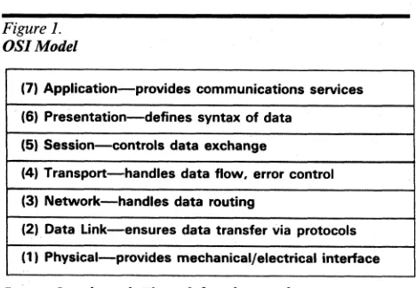
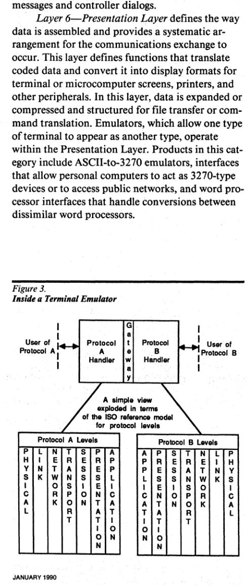
The OSI Model
The International Organization for
Standardiza-tion (ISO) Open Systems InterconnecStandardiza-tion (OSI)
reference model provides a framework for
under-standing the differences in conversion products.
Each of the model's layers defines a particular
as-pect of the entire data communications process.
Figure 1 illustrates the seven-layer hierarchy.
Layer l-Physical Connection provides
me-chanical and electrical specifications and
proce-dures to establish, maintain, and end physical
connections. This layer defines interface, code,
speed, and synchronization functions. Layer 1
cov-ers interface, code, and
asynchronous-to-synchronous converters.
Layer 2-Data Link Control ensures that the
data passes without error from one computer to
another. This process involves protocols that
spec-ify the format for data transmission. Protocol
con-verters handle conversions in this layer.
@ 1991 McGraw-Hili, Incorporated. Reproduction Prohibited. Datapro Research Group. Delran NJ 08075 USA
C23-010-203
Protocol Conversion Systems
Figure 1.
The OS] Model
(7) Application-provides communications services
(6) Presentation-defines syntax of data
(5) Session-controls data exchange
(4) Transport-handles data flow, error control
(3) Network-handles data routing
(2) Data Link--ensures data transfer via protocols
(1) Physical-provides mechanicaVelectrical interface
Layers One through Three define the interface
between the host computer and the network.
Layers Four through Seven provide
compati-bility to dataformat and exchange.
Parameters such as modem control, ring signaling,
and dedicated connections fall into this category.
Layer 3-Network Layer allows two systems
to exchange data. This layer defines packet
ad-dressing and data routing to final destination.
Units that handle conversion in this layer include
gateway devices, such as packet assemblers/
disassemblers (PADs) that provide access to X.25
networks or between local area networks.
Front-end processors (FEPs) with protocol conversion
functions also fall into this classification.
Layer 4-Transport Layer handles
end-to-end error and flow control to ensure that the
com-munications exchange is orderly and reliable. PAD
devices, a type of gateway product, are the major
products in this layer.
Layer 5-Session Layer furnishes the
struc-ture for a data exchange by managing connections
between application processes, establishing and
terminating connections, and sending end-to-end
messages and controller dialogs.
Layer 6-Presentation Layer defines the way
data is assembled and provides a systematic
ar-rangement for the communications exchange to
occur. This layer defines functions that translate
coded data and convert it into display formats for
terminal or microcomputer screens, printers, and
other peripherals. In this layer, data is expanded or
compressed and structured for file transfer or
com-mand translation. Emulators, which allow one type
of terminal to appear as another type, operate
within the Presentation Layer. Products in this
cat-egory include ASCII-to-3270 emulators, interfaces
[image:3.612.352.587.77.253.2]C23-010-204
Protocol Conversion SystemsFigure 2.
The Protocol Conversion Process
1- - - -: - - - -
-"I
T1
1 •
H
1
1
~o I
1
1
1
~---n•
Ithat allow personal computers to act as 3270-type
devices or to access public networks, and word
pro-cessor interfaces that handle conversions between
dissimilar word processors.
Layer 7-Applications Layer
supports user
and application tasks by providing the
communi-cations services for specific computer applicommuni-cations.
Basically, this layer provides the meaning to the
message.
Converters often provide translations on
more than one level in the model. Conversion at
one layer generally implies a need for compatibility
in lower layers. For example, a protocol converter
working on Level 2 functions also assumes
respon-sibility for compatibility in the interface, code, and
synchronization functions.
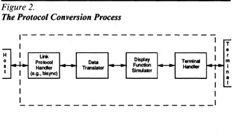
The Mechanics of Protocol Conversion
Protocol converters translate for dissimilar devices
by simulating the appropriate protocol for each. As
Figure 2 shows, this functionality gives protocol
converters a distinctive, double-ended structure.
For each end of the conversion process, a local
pro-tocol handler uses the propro-tocol required by the
at-tached device. Connecting these handlers is a
gateway task that implements the movement of
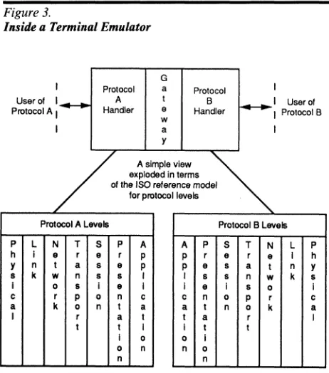
user data between the handlers. If all
communica-tion protocols were structured in accordance with
the OSI Reference Model, the converter would
im-plement a set of seven-layer OSI protocols joined
by the gateway task. Because the central task of a
fully structured OSI protocol is to isolate users
from the communication environment, a protocol
converter dealing exclusively with full OSI model
protocols would be fairly simple to develop and
could operate with few restrictions. With non-OSI
protocols, such as those commonly used in today's
networks, the following issues complicate the
con-version process:
JANUARY 1991
Protocol Conversion
S,stems:
Technolog, Overview
Datapro Reports on Data Communications
The format of the user data.
If the data is
eas-ily separated from communication and device
con-trol protocols, it is more easily transferred to
another environment. Special features, such as
data compression, complicate protocol conversion
if they do not exist in the other protocol.
The degree of layering in the protocols.
Al-though full compliance with the OSI model is
un-likely, any amount of OSI-like layering in the
protocols will aid in the separation of useful data
from control information that must not be
intro-duced into the other environment.
The availability of common functions in the
protocols involved.
Data exchange between the
us-ers requires a degree of synchronization between
the two foreign protocols. For example, most older
protocols operate in half-duplex mode-only one
station at a time can send information.
It
is
neces-sary for converters operating between half-duplex
protocols to ensure that both stations are not given
permission to send at the same moment, since
nei-ther could receive under those circumstances.
When protocol converters allow devices to
simulate other devices, device control protocol
translation may be needed. IBM's popular 3270
series of terminals is often emulated by lower cost
asynchronous devices, but the 3270 has special
fea-tures, such as the capability to return only
modi-fied fields to the host computer. This capability
must be emulated within the protocol converter.
Figure 3 shows the structure of a terminal emulator
protocol converter.
Products
Interface and Code Converters
An interface provides the physical connection
be-tween two devices. Interface conversion offers the
lowest level of established compatibility. Data and
control lines from devices terminate at a connector
that handles assigned signal functions. For
exam-ple, the RS-232-C interface connector has 25
pins-l pin per function. The interface also
pre-scribes voltage levels for electrical signals passing
over the data and control lines.
Interface converters
serve as adapters for
fering interfaces, accept the connectors of two
dif-ferent interfaces, and/or translate signals and
voltage levels of one interface to another. Interface
@ 1991 McGraw-Hili, Incorporated. Reproduction Prohibited. Datapro Research Group. Delran NJ 08075 USA
/
(
[image:5.612.106.337.75.337.2]Datapro Reports on Data Communications
Figure 3.
Inside a Terminal Emulator
I Protocol G a
Protocol Conversion Systems:
Technology Overview
Protocol I User of ' . - - A t B
1---'
User of Protocol A I Handler e Handler I Protocol Bw
I a I
y
/
exploded In termsA.~._ ~
of the ISO reference model for protocolleYels
Protocol A Levels Protocol B LeYels
P L N T S
P
A AP
S T N LP
h I e r e r p p r e r e I h Y n t
a
8 e p p es
a t n yB k
w
n B B I I B B nw
ks
I 0 8 Ie
I Ie
I B 0 Ic r p 0 n c c n 0 p r c
a
k 0 n ta
a t n 0 ka
I r
a
I ta
r It t I I t t
I 0 0 I 0 n n 0
n n
conversions commonly occur between RS-232-C
and MIL-STD-188 or between RS-232-C and V.35.
Code converters
translate one
communica-tions code to another. The most common codes are
ASCII, EBCDIC, and Baudot. Conversion from
one code to another may be simple, involving only
the addition or deletion of control bits or the
alter-ation of parity. A more complex code conversion
might require changing the data character's bit
pat-tern.
Basic code conversion hardware consists of
two universal synchronous/asynchronous receiver/
transmitters (USARTs), a translation table
con-tained in ROM, and control circuitry. Characters
received by the USART in one code are mapped in
the ROM table into a corresponding character in
the destination device's code. Converted data goes
to the other USART, which transmits it to the
des-tination device.
Asynchronous-to-synchronous converters
con-vert data from asynchronous terminals for use on
synchronous facilities.
Protocol Converters
Protocol converters, one of the largest categories of
conversion devices, perform changes at the Data
Link Layer to ensure device compatibility.
Proto-col converters connect incompatible peripheral
devices to hosts via microprocessors. A protocol
converter actually changes one protocol to another
@ 1991 McGraw-Hili, Incorporated. Reproduction Prohibited. Datapro Research Group. Delran NJ 08075 USA
C23-010-205
Protocol Conversion Systemsby separating control characters from data and
as-sembling the new data stream according to new
specifications.
During the conversion sequence, the
con-verter accepts blocks of data, adds or deletes the
necessary control characters, reformats the block,
and calculates the required check characters so the
receiving device receives characters formatted
ac-cording to its requirements. For example, in an
ASCII-to-SDLC conversion, the converter accepts
a character string, eliminates start and stop bits,
assembles characters into a block, and adds
head-ers and trailhead-ers to create complete frames. In a
BSC-to-SDLC conversion, the converter changes
the first four SYN bits of the bisync algorithm to
the first flag bit of the SDLC algorithm.
Since protocol converters must stop, store,
process, and retransmit data, they usually increase
response time. The device generally accepts
low-speed input in the buffer, works with the data, and
then transmits it out in short, high-speed bursts.
Gateways and PADs
Gateways and PADs perform conversions on OSI
Layers Three and Four (the Network and
Trans-port Layers) and also perform lower layer
func-tions. Gateway devices allow access to
incompatible networks, such as between SNA and
DECnet, or between SNA and Ethernet, or
be-tween a data communications device and an X.25
public data network. Gateways also extend
com-patibility to the inherent protocols, codes, and
in-terfaces of network architectures. By far the largest
subset of gateway products are packet assembler/
disassemblers (PADs). Datapro covers these
de-vices in separate "Local Area Network Products"
and "Packet Assemblers/Disassemblers" reports.
Emulation Devices
An emulator resolves incompatibilities, including
differences in protocol, code, interface, device
characteristics, and link characteristics. To the
em-ulator, protocol conversion is secondary.
Many-but not all-protocol converters
to-day provide protocol conversion and emulation,
whereas all emulation devices provide protocol
conversion. Commonly, devices performing
proto-col and emulation translations are called
value-added terminal controllers, remote cluster
controllers, or terminal emulators.
C23-010-206
Protocol Conversion Systems
An IBM 327X communications processor
serves up to 32 IBM 3277-type terminals on a
mul-tipoint line. Data moving in this configuration is
blocked out in 1 ,920-character screen images
(blocks of data). If a user wants to replace IBM
3277 terminals with asynchronous ASCII devices,
the ASCII units must appear as IBM 3277s to the
IBM host. A terminal controller/emulator solves
the problem by accumulating an asynchronous
datastream in its buffer until a 1,920-character
screen image is filled or until the emulator receives
an end-of-record, end-of-block control character.
The terminal controller converts the ASCII
termi-nal protocol to the host protocol (Le., BSC),
rear-ranges the data format to appear as if it comes
from an IBM 327X, and transfers the screen image
to the host, which recognizes the data as that of an
IBM 3277-not an asynchronous ASCII terminal.
The terminal controller performs all functions of
the device it replaces, including data
concentra-tion, poll/select, flow control, buffering, error
de-tection and correction, and interfacing of multiple
·attached terminals.
Sometimes the emulating device connects to
an IBM cluster controller rather than replacing it.
In this situation, it then, in effect, performs the
conversion between the terminal and the IBM
con-troller instead of between the concon-troller and the
JANUARY 1991
Protocol Conversion Systems:
Technology Overview
Datapro Reports on Data Communications
host. These emulators allow the user to integrate
incompatible equipment into an existing terminal
cluster.
During an emulation/conversion/transfer
se-quence, the emulator interprets control sequences
from a terminal to simulate the emulated
termi-nal's operations. The equivalent control sequences
of various terminals differ widely. For example, no
asynchronous ASCII keyboard provides all of the
special 3270 function
keys~
Many users install terminal controllers to
al-low non-IBM devices in remote locations to access
IBM mainframes. Many remote controllers have
one synchronous line for 3270 access and two or
more minicomputer interfaces. Local users can
switch between hosts, depending on the
applica-tion.
Although most protocol conversion systems
perform ASCII-to-IBM conversions, other
prod-ucts provide the conversion required between IBM
BSC protocols and IBM SDLC protocols. Users of
older IBM BSC equipment who plan to migrate to
an SNA/SDLC environment benefit from these
products without replacing their old equipment.
BSC-to-SDLC conversions generally occur between
BSC 2780/3780 RJE or 3270 BSC protocols and
SDLC protocols . •
@ 1991 McGraw-Hili, Incorporated. Reproduction Prohibited. Datapro Research Group. Delran NJ 08075 USA
(
cIalapft)"
Datapro Reports on DataCommunications
C23-010-201
Protocol Conversion Systems
Protocol Conversion
Systems:
Technology Overview
In this report:
Synopsis
Protocols ...
-202
Editor's Note
This report concentrates on the
tech-Types of Protocols ...
-202
nology of standalone hardware
prod-ucts that perform protocol
conver-The OSI Mode!... ...
-203
sions. For a market overview, see
Report C23-01O-lOi. For
compari-sion columns, see Report
C23-010-301. For information on software
packages performing conversion and
emulation, consult the
Datapro
Di-rectory of Software
and the
Datapro
Directory of Microcomputer Software.
For coverage of micro-to-mainframe
conversion products, see Report
C22-010-101, "PC-to-Host
Commu-nications Products," in this volume.
Highlights
Protocol conversion reformats or
converts one protocol to another. In
most instances, a protocol converter
takes asynchronous data and alters it
for transmission on a synchronous
data link. The device can also
per-form the opposite function; i.e.,
re-formatting synchronous data for
transmission on an asynchronous
data link.
Some of the most common protocols
are the American Standard Code for
Information Interchange (ASCII),
IBM's Extended Binary Coded
Deci-mal Interchange Code (EBCDIC),
@ 1990 McGraw-Hili. Incorporated. Reproduction Prohibited. Datapro Research. Delran NJ 08075 USA
IBM's Binary Synchronous
Commu-nication (BSC), and the CCITT's
High-Level Data Link Control
(HDLC).
Protocol conversion systems
origi-nated as "passports" into the IBM
communications world, which IBM
designed in a synchronous mode.
Most terminals on the market,
how-ever, are asynchronous, as are a high
percentage of the modems in the
United States. Protocol converters
maintain peaceful coexistence
be-tween terminals and IBM hosts,
al-lowing information to flow freely.
As demand increased, other methods
of protocol conversion evolved, such
as through software in front-end
pro-cessors, adapter devices, X.25
con-verters, cluster controllers, data
switches, packet assemblers/
disassemblers (PADs), gateways, and
network processors. Emulation
de-vices also resolve incompatibility
problems such as differences in
pro-tocols, codes, interfaces, and device
and link characteristics.
C~3-01
0-202
Protocol Conversion
Systems
Analysis
Protocol conversion often involves far more than
simply translating one protocol to another. The
process can occur through mUltiple products, such
as emulation devices, gateways, and packet
assemblers/disassemblers (PADs), that foster
com-patibility among communications devices, local
area networks, packet switched networks, or
com-puter operating systems. Products can range from
microprocessor-based circuit boards to front-end
processors (FEPs) capable of performing
conver-sion functions through software. Some devices
per-form only code or interface conversions, while
others perform protocol conversion, device
emula-tion, and/or code and interface translations in the
same unit.
This report focuses on standalone hardware
products that perform conversions allowing
equip-ment from one manufacturer to communicate with
equipment from another. The largest market
seg-ment addresses incompatibilities between the
syn-chronous communications used by IBM
[image:8.612.68.302.534.696.2]mainframes and asynchronous ASCII terminals.
Figure 1.
OSIModel
(7) Application-provides communications services
(6) Presentation-defines syntax of data
(5) Session-controls data exchange
(4) Transport-handles data flow. error control
(3) Network-handles data routing
(2).
Data Link-ensures data transfer via protocols
(1) Physical-provides mechanical/electrical interface
Layers One through Three define the interface
between the host computer and the network.
Layers Four through Seven provide
compati-bility to. data format and exchange.
JANUARY 1990
Protocol Conversion
Systems:
Technology Overview
Protocols
Datapro Reports on Data
Communications
Protocols govern the format of a data exchange,
recognition of a remote connection, identification
of the transmitting and receiving locations,
trans-mission sequence, handling of interruptions,
error-checking methods and control, methods of
blocking data, and security procedures. They range
from single character-by-character
communica-tions with no error checking to complex algorithms
moving data among many devices.
In general, protocols specify three major
ar-eas:
• The method in which data is to be represented
or encoded-the code set. Most data processing
systems use either the American Standard Code
for Information Interchange (ASCII) or IBM's
Extended Binary Coded Decimal Interchange
Code (EBCDIC).
• The method in which the codes are transmitted
and received-asynchronous or synchronous.
In asynchronous transmission, data is sent with
start and stop bits between individual
charac-ters at random intervals with no specific timing.
In synchronous transmission, characters or bits
are sent at a fixed rate; transmitting and
receiv-ing devices are synchronized, eliminatreceiv-ing the
need for start/stop bits.
• The nondata exchanges of information by
which the two devices establish control, detect
failures or errors, and initiate corrective action.
Through hardware or software, the sending device
automatically formats the data and adds the
re-quired bits before transmitting each character or
block. The receiving device automatically checks
each of the appended bits before acknowledging
receipt of data. After detecting failures, the
proto-col initiates error-control procedures.
Types of Protocols
Byte-oriented protocols
require transmission of
data in eight-bit blocks; each transmitted block
re-quires an acknowledgment before the next block
can be sent.
Bit-oriented protocols
allow data to be
transmitted in blocks of any length up to a
speci-fied maximum; an acknowledgment may take place
after one or several blocks have been sent,
depend-ing on the protocol. Some of the most common
@ 1990 McGraw-Hili, Incorporated. Reproduction Prohibited. Datapro Research.
(
(
Datapro Reports on Data Communications
Protocol Conversion
Systems,
Technology Overview
protocols are ASCII or Teletype (TTY), IBM's
Syn-chronous Data Link Control (SDLC), and IBM's
Binary Synchronous Communications (BSC).
ASCII or TTY -ASCII or TTY protocol
tra-ditionally relates to teletypewriter equipment and
services. An asynchronous protocol, ASCII
pro-vides very little error checking. Transmission
oc-curs in the form of a start bit, a number of data bits
(usually five to eight), and one or more stop bits.
Data in ASCII protocol enters the communications
line at any time. The end of the link is
synchro-nized through the specifications of a common line
speed and detection of the start bits and the
begin-ning of the character transmission. ASCII requires
an acknowledgment after each block is sent.
IBM's Synchronous Data Link Control
(SDLC)-a bit-oriented synchronous protocol that
uses a synchronized series of frames. Each frame
has a synchronization flag, followed by an address
field, a control field identifying the purpose of the
transmission, the data itself, a frame-check field,
and a trailing flag. The flag character marks
syn-chronization. SDLC permits up to 127 frames to
be outstanding before requiring an
acknowledg-ment. Private-line networks use SDLC.
IBM Binary Synchronous Communications
(BSC)-a character-oriented synchronous protocol,
also referred to as
bisync. Binary synchronous data
and control characters consist of eight-bit bytes. A
transmission in BSC incorporates a number of
syn-chronizing (SYN) characters that ensure
synchroni-zation at both ends of the communications link.
These characters are followed by a start-of-text
(STX) character, a block of text, an end-of-text
(ETX) character, and a block error-checking
char-acter (BCC). BSC does not support full-duplex
transmission, nor is it supported by IBM's Systems
Network Architecture (SNA). An acknowledgment
must follow each block of data. The BSC protocol
works in multipoint applications over private lines.
Other communications protocols include
High-Level Data Link Control (HDLC), a
CCITT-specified, bit-oriented protocol on which most
other bit-oriented protocols are based; Univac
U200, CDC UT200, and Burroughs Multipoint
Poll Select, which can run on synchronous and
asynchronous links; and Digital's Digital Data
Communications Message Protocol (DDCMP), a
byte-oriented protocol that can accommodate 255
unacknowledged transmissions.
@ 1990 McGraw-Hili. Incorporated. Reproduction Prohibited. Datapro Research. Delran NJ 08075 liSA
The OSI Model
C23-010-203
Protocol Conversion Systems
The International Organization for
Standardiza-tion (ISO) Open Systems InterconnecStandardiza-tion reference
model provides a framework for understanding the
differences in conversion products. Each of the
model's layers defines a particular aspect of the
entire data communications process. Figure 1
illus-trates the seven-layer hierarchy.
Layer I-Physical Connection provides
me-chanical and electrical specifications and
proce-dures to establish, maintain, and end physical
connections. This layer defines interface, code,
speed, and synchronization functions. Layer 1
cov-ers interface, code, and
asynchronous-to-synchronous converters.
Layer 2-Data Link Control ensures that the
data passes without error from one computer to
another. This process involves protocols that
spec-ify the format for data transmission. Protocol
con-verters handle conversions in this layer.
Parameters such as modem control, ring signaling,
and dedicated connections fall into this category.
[image:9.612.306.542.543.744.2]Layer 3-Network Layer allows two systems
to exchange data. This layer defines packet
ad-dressing and data routing to final destination.
Units that handle conversion in this layer include
gateway devices, such as packet assemblersl
disassemblers (PADs) that provide access to X.25
networks or between local area networks.
Front-end processors (FEPs) with protocol conversion
functions also fall into this classification.
Figure 2.
The Protocol Conversion Process
r---l
HI
Unk Data Display rermlnalI
=
PrOtO .. COI Tranllalor Function HandlerI
Han er SlmulalorI (e.g .• BIsync)
I
I
L _________________
~C23·01
()'204
Protocol Conversion SystemsLayer 4-Transport Layer handles
end-to-end error and flow control to ensure that the
com-munications exchange is orderly and reliable. PAD
devices, a type of gateway product, are the major
products in this layer.
Layer 5-Session Layer furnishes the
struc-ture for a data exchange by managing connections
between application processes, establishing and
terminating connections, and sending end-to-end
messages and controller dialogs.
[image:10.612.65.310.191.770.2]. Layer 6-Presentation Layer defines the way
data is assembled and provides a systematic
ar-rangement for the communications exchange to
occur. This layer defines functions that translate
coded data and convert it into display formats for
terminal or microcomputer screens, printers, and
other peripherals. In this layer, data is expanded or
compressed and structured for file transfer or
com-mand translation. Emulators, which allow one type
of terminal to appear as another type, operate
within the Presentation Layer. Products in this
cat-egory include ASCII-to-3270 emulators, interfaces
that allow personal computers to act as 3270-type
devices or to access public networks, and word
pro-Cessor interfaces that handle conversions between
dissimilar word processors.
Figure
3.
Inside a Terminal Emulator
I
G
I
I
a
~I
User of
User of .
1+-+
Protocol
t
Protocol
Protocol AI
A
e
B
IProtocol B
. Handler
w
Handler
I
a
I
'I
h
A
_ . -
A
exploded in terml
of the
ISO .reference model
for protocol levell
Protocol A levels
Protocol B levell
P
L
N
T
S
P
A
A
P
S
T
N
L
P
H
I
E R
E R P
P
R
E R
E I
H
V
N
T
A
S
E P
P
E
S
A
T
N
V
S
KW
N
S
S
L
L
S
S
N
W
KS
I
0
S
I
E I
I
E
I
S
0
I
C
R P
0
N C
C
N
0
P
R
C
A
K0
N
T
A
A
T
N
0
KA
l
R
A
T
T
A
R
l
T
T
I
I
T
T
I
0
0
I
0
N
N
0
N
N
JANUARY 1990
--~---Protocol Conversion
Systems.
Technology Overview
Datapro Reports on Data Communications
Layer 7-Applications Layer supports user
and application tasks by providing the
communi-cations services for specific computer applicommuni-cations.
Basically, this layer provides the meaning to the
message.
Converters often provide translations on
more than one level in the model. Conversion at
one layer generally implies a need for compatibility
in lower layers. For example, a protocol converter
working on Level 2 functions also assumes
respon-sibility for compatibility in the interface, code, and
synchronization functions.
Mechanics of Protocol Conversion
Protocol converters translate for dissimilar devices
by simulating the appropriate protocol for each. As
Figure 2 shows, this functionality gives protocol
converters a distinctive, double-ended structure.
For each end ofthe conversion process, a local
pro-tocol handler uses the propro-tocol required by the
at-tached device. Connecting these handlers is a
gateway task that implements the movement of
user data between the handlers. If all
communica-tion protocols were structured in accordance with
the OSI Reference Model, the converter would
im-plement a set of seven-layer OSI protocols joined
by the gateway task. Because the central task of a
fully structured OSI protocol is to isolate users
from the communication environment, a protocol
converter dealing exclusively with full OSI model
protocols would be fairly simple to develop and
could operate with few restrictions. With non-OSI
protocols, such as those commonly used in today's
networks, the following issues complicate the
con-version process:
The format of the user data. If the data is
eas-ily separated from communication and device
con-trol protocols, it is more easily transferred to
another environment. Special features such as data
compression complicate protocol conversion if
they do not exist in the other protocol.
The degree of layering in the protocols.
AI·
though full compliance with the OSI model is
un-likely, any amount of OS I-like layering in the
protocols will aid in the separation of useful data
from control information that must not be
intro-duced into the other environment.
The availability of common functions in the
protocols involved. Data exchange between the
us-ers requires a degree of synchronization between
the two foreign protocols. For example, most older
Ii> 1990 McGraw-Hili, Incorporated. Reproduction Prohibited. Datapro RE1search. Delran NJ 08075 USA - .
(
Datapro Reports on Data Communications
Protocol Conversion Systemsl
Technology Overview
protocols operate in half-duplex mode-only one
station at a time can send information.
It
is
neces-sary for converters operating between half-duplex
protocols to ensure that both stations are not given
permission to send at the same moment, since
nei-ther could receive under those circumstances.
When protocol converters allow devices to
simulate other devices, device control protocol
translation may be needed. IBM's popular 3270
series ofterminals is often emulated by lower cost
asynchronous devices, but the 3270 has special
fea-tures, such as the capability to return only
modi-fied fields to the host computer. This capability
must be emulated within the protocol converter.
Figure 3 shows the structure of a terminal emulator
protocol converter.
Additional Converters
An interface provides the physical connection
be-tween two devices. Interface conversion offers the
lowest level of established compatibility. Data and
control lines from devices terminate at a connector
that handles assigned signal functions. For
exam-ple, the RS-232-C interface connector has 25
pins-l pin per function. The interface also
pre-scribes voltage levels for electrical signals passing
over the data and control lines.
Interface converters serve as adapters for
fering interfaces, accept the connectors of two
dif-ferent interfaces, and/or translate signals and
voltage levels of one interface to another. Interface
conversions commonly occur between RS-232-C
and MIL-STD-188 or between RS-232-C and V.35.
Code converters translate one
communica-tions code to another. The most common codes are
ASCII, EBCDIC, and Baudot. Conversion from
one code to another may be simple, involving only
the addition or deletion of control bits or the
alter-ation of parity. A more complex code conversion
might require changing the data character's bit
pat-tern.
Basic code conversion hardware consists of
two universal synchronous/asynchronous receiver/
transmitters (USARTs), a translation table
con-tained in ROM, and control circuitry. Characters
received by the USART in one code are mapped in
the ROM table into a corresponding character in
the destination device's code. Converted data goes
to the other USART, which transmits it to the
des-tination device.
@ 1990 McGraw-Hili, Incorporated. Reproduction Prohibited. Oatapro Research. Delran NJ 08075 USA
C23-010-205
Protocol Conversion SystemsAsynchronous-lo-synchronous converters
con-vert data from asynchronous terminals for use on
synchronous facilities.
Protocol Converters
Protocol converters, one of the largest categories of
conversion devices, perform changes at the Data
Link Layer to ensure device compatibility.
Proto-col converters connect incompatible peripheral
devices to hosts via microprocessors. A protocol
converter actually changes one protocol to another
by separating control characters from data and
as-sembling the new datastream according to new
specifications.
During the conversion sequence, the
con-verter accepts blocks of data, adds or deletes the
necessary control characters, reformats the block,
and calculates the required check characters so the
receiving device receives characters formatted
ac-cording to its requirements. For example, in an
ASCII-to.;.SDLC conversion, the converter accepts
a character string, eliminates start and stop bits,
assembles characters into a block, and adds
head-ers and trailhead-ers to create complete frames. In a
BSC-to-SDLC conversion, the converter changes
the first four SYN bits of the bisync algorithm to
the first flag bit of the SDLC algorithm.
Since protocol converters must stop, store,
process, and retransmit data, they usually increase
response time_ The device generally accepts
low-speed input in the buffer, works with the data, and
then transmits it out in short, high-speed bursts.
Gateways and PADs
Gateways and PADs perform conversions on OSI
LayersThree and Four (the Network and
Trans-port Layers) and also perform lower layer
func-tions. Gateway devices allow access to
incompatible networks, such as between SNA and
DECnet, or between SNA and Ethernet, or
be-tween a data communications device and an X.25
public data network. Gateways also extend
com~
patibility to the inherent protocols, codes, and
in-terfaces of network architectures. Datapro covers
these devices in Report CII-OlO-30l, "Local Area
Network Products." By far the largest subset of
gateway products are packet assembler/
disassemblers (PADs). We now cover these
prod-ucts in a separate report, Report C20-0lO-30l,
"X.25 Packet Assemblers/Disassemblers (PADs)."
C23-010-206
Protocol Conversion SystemsEmulation Devices
An emulator resolves incompatibilities including
differences in protocol, code, interface, device
characteristics, and link characteristics. To the
em-ulator, protocol conversion is secondary.
Many-but not all-protocol converters
to-day provide protocol conversion and emulation,
whereas all emulation devices provide protocol
conversion. Commonly, devices performing
proto-col and emulation translations are called
value-added terminal controllers, remote cluster
controllers, or terminal emulators.
An IBM 3271 serves up to 32 IBM 3277-type
terminals on a multipoint line. Data moving in this
configuration is blocked out in 1,920-character
screen images (blocks of data). If a user wants to
replace IBM 3277 terminals with asynchronous
ASCII devices, the ASCII units must appear as
IBM 3277s to the IBM host. A terminal controller/
emulator solves the problem by accumulating an
asynchronous datastream in its buffer until a
1,920-character screen image is filled or until the
emulator receives an end-of-record, end-of-block
control character. The terminal controller converts
the ASCII terminal protocol to the host protocol
(i.e., BSC), rearranges the data format to appear as
ifit comes from an IBM 3271, and transfers the
screen image to the host, which recognizes the data
as that of an IBM 3277-not an asynchronous
ASCII terminal. The terminal controller performs
all functions of the device it replaces, including
data concentration, poll/select, flow control,
buff-ering, error detection and correction, and
interfac-ing of multiple, attached terminals.
JANUARY 1990
Protocol Conversion Systems:
Technology Overview
Datapro Reports on Data Communications
Sometimes the emulating device connects to
an IBM cluster controller rather than replacing it.
In this situation, it then, in effect, performs the
conversion between the terminal and the IBM
con-troller instead of between the concon-troller and the
host. These emulators allow the user to integrate
incompatible equipment into an existing terminal
cluster.
During an emulation/conversion/transfer
se-quence, the emulator interprets control sequences
from a terminal to simulate the emulated
termi-nal's operations. The equivalent control sequences
of various terminals differ widely. For example, no
asynchronous ASCII keyboard provides all of the
special 3270 function keys.
Many users install terminal controllers to
al-low non-IBM devices in remote locations to access
IBM mainframes. Many remote controllers have
one synchronous line for 3270 access and two or
more minicomputer interfaces. Local users can
switch between hosts, depending on the
applica-tion.
Although most protocol conversion systems
perform ASCII-to-IBM conversions, other
prod-ucts provide the conversion required between IBM
BSC protocols and IBM SDLC protocols. Users of
older IBM BSC equipment who plan to migrate to
an SNAlSDLC environment benefit from these
products without replacing their old equipment.
BSC-to-SDLC conversions generally occur between
BSC 2780/3780 RJE or 3270 BSC protocols and
SDLC protocols . •
@ 1990 McGraw-Hili, InCQrporated. Reproduction Prohib~ed, DlIUlprQ Research .•
Protocol Conversion System/Terminal Controller
Comparison Columns
VENDOR NAME Arkansas SystamB Arkansas 8ystams Arkansas Systams
PRODUCT NAME PATH I PATH II PATH III
DeVICE TYPE Protocol converter Protocol converter Protocol converter
CONVERSION PERFORMED 3780 to 3270 8SC to SDLC Vendor did not specify
SPECIFIC DEVICE EMULATED Vendor did not specify ISM 5151/12 3780
SPECIFIC FUNCTIONALITY PROVIDED ISM S/3X 3270 terminals ISM 3270/IBM 5250 SNA Vendor did not specify
VIRTUAL SCREEN.SIZES SUPPT. (char.) Vendor did not specify 1,920 Vendor did not specify
COMMAND PORT SUPPORTED No No No
HOST SIDE SPECIFICATIONS
Specific Hosts Supported ISM System 3X IBM System 3X IBM System 3X
Host Operating Systems Supported Vendor did not specify Vendor did not specify Vendor did not specify
Number Host Selections Suppt. Concurrently 2 BSC 1 BSC & 1 SOLC 2 BSC 3780s
Connectors Supported Direct connection, Direct connection, Direct connection multipoint on leased Ilna, multipoint on leased line,
~int-to-Sioint on dial-up ~int-to-point on dial-up
Connection to Host via Controller endor id not specify endor did not specify Vendor did not specify
TRANSMISSION SPECs{HOST LINE
Maximum Transmission peed (bps) 9800 19.2K 9800
§ynchronization Synchronous Synchronous Synchronous
Transmission Mode Full duplex Full du&\ex Full dfrlex
Protocols Supported 3780 SNA/ LC BSC, NA/SDLC
Codes Supported EBCotC EBCDIC EBCDIC
Intarface 1 RS-232-C 1 RS-232-C 1 RS-232-C
Clockin9 Internal, external Internal, external Internel, external
TERMINAL SIDE SPEC./TERMINAL LINE
Number and Type of Ports Provided 1 (multid~ for up to 1 multidrop 3270 Nne 3780 6 terminals
Specific Devices Supported ISM 3274, 3276 teller 3270 competible (incl. Any 3780 device terminals, ATMs, A TM A TMs, teller terminals)
switches
Connections Supported Leased Direct connection, ramote, Diract connection dial-up, leased
TRANSMISSION SPEC~ERMINAL LINE
Maximum Transmission eed (bes) 9600 9800 9800
Maximum AI/gregate Input Rate (
PSt
9800 9800 9600SynchronizatIOn Sync~nous Synchronous Synchronous
Transmission Mode Full d plex Full duplex ~duPlex
Protocols Supported BSC BSC
Codes supru:rted EBCDIC EBCDIC EBCDIC
Interfaces upported RS-232-C RS-232-C RS-232-C
DIAGNOSTICS Self-test, problem Self-test, problem Self-test annunciation annunciation
PRICING AND AVAILABILITY
Purchase ($) Contect vandor Contact vendor Contact vendor Rentel ($/month) Vandor did not specify Vendor did not specify Vendor did not specify InsteUation ($) Vendor did not specify Vandor did not specify Vendor did not specify Maintenance IS/year) Vendor did not specify Vendor did not specify Vendor did not specify Serviced by Arkansas Systems Arkansas Systems Arkansas Systems
Availabil~ (days ARO) Immediate Immediata Immediate Date of F ret. Commercial Delivery 1985 1985 1986
Number Installed to Dete 25 15 10
COMMENTS
-
Full display mapping-~IuS user-defined eyboard
NOVEMBER 1988
COPYRIGHT
@1988 McGRAW-HILL, INCORPORATED. REPRODUCTION PROHIBITED
DATAPRORESEARCH, DELRAN, NJ 08075 USA
C23-010-201
Protocol Conversion
Systems
Arkansas Systams
PATH IV
Protocol converter
Vendor did not specify
IBM 5251/12
IBM S/3X3624 ATM
1,920
No
IBM System 3X
Vendor did not specify
1 BSC & 1 SDLC
Direct connection, multipoint on leased line,
~int-to-point on dial-up endor did not specify
19.2K
Synchronous Full dfrlex BSC, NA/SDLC
EBCDIC
1 R8-232-C
Internal, external
Multidrop leased lines
IBM 3624, ATM
Remote, leased
9800 9600 Synchronous Full duplex BSC
EBCDIC RS-232-C
Self-test
Contact vendor Vendor did not specify Vendor did not specify Vendor did not specify Arkansas Systems Immediate 1986
Vendor did not specify
C23-010-202
Protocol Conversion
Systems
VENDOR NAME
PRODUCT NAME
DEVICE TYPE
CONVERSION PERFORMED
SPECIFIC DEVICE EMULATED
SPECIFIC FUNCTIONALITY PROVIDED
VIRTUAL SCREEN SIZES SUPPT. (char.)
COMMAND PORT SUPPORTED
HOST SIDE SPECIFICATIONS Specific Hosts Supponed
Host Operating Systems Supponed
Number Host Selections Suppt. Concurrently
Connectors Supponed
Connection to Host via Controller
TRANSMISSION SPEC./HOST LINE Maximum Transmission Speed (bps)
Synchronization Transmission Mode Protocols Supponed
Codes Supponed
Interface
Clocking
TERMINAL SIDE SPEC./TERMINAL LINE Number and Type of Pons Provided
Specific Devices Supponed
Connections Supponed
TRANSMISSION SPECC,ERMINAL LINE Maximum Transmission peed (bgs) Maximum A!jgregate Input Rate ( psI SynchronizatIon
Transmission Mode Protocols Supponed
Codes supc,oned Interfaces upponed
DIAGNOSTICS
PRICING AND AVAILABILITY Purchase ($)
Rental ($/month) Installation ($) Maintenance ($ /vear) Serviced by Availability (days ARO) Date of First Commercial Delivery Number Installed to Date
COMMENTS
Protocol Conversion System/Terminal Controller
Comparison Columns
Arkan . . s Systems Arkansas Systems Arkansas Systems
PATH IX PATH V PATH VI
Protocol convener Protocol convener Protocol convener
ASCII to EBCDIC, Burroughs
Poll Select to IBM 5250 8urrou~s IBM 5 0 SDLC remote Poll Select to ASCII to EBCDIC, Burroughs Poll Select to IBM 5250
SDLC remote SDLC remote
IBM 5251/11 IBM 5251/12 IBM 5251/11
Burr. Poll Select/IBM 5250 IBM 5250/Burroughs (sync) Burr. Poll Select/IBM 5250
1,920 1,920 1,920
No No No
IBM System 3X IBM System 3X IBM System 3X
Vendor did not specify Vendor did not specify Vendor did not specify
Twinax SDLC 5250 Twinax
Direct connection Direct connection, Direct connection
Vendor did not specify
multipoint on leased line, \feint-t0-;\l0int on dial-up
endor id not specify Vendor did not specify
1M 1M 1M
Synchronous Synchronous Synchronous Full d~lex Full d~lex Full dfclex
SNA/ DLC SNA/ DLC SNAt DLC
EBCDIC EBCDIC EBCDIC
Twinax Vendor did not specify Twinax
Vendor did not specify Vendor did not specify Vendor did not specify
Multiple terminals Multidrop Burroughs Multiple terminals synchronous
Vendor did not specify All sync Poll Select Vendor did not specify devices
Remote, leased, multidrop Remote, leased Remote, leased, multidrop
9600 9600 96oo
9600 9600 9600
As~nchronous Asrnchronous As~nchronous
Ha duplex Ha duplex
Poll select
~~II~~r.:
Poll selectASCII ASCII ASCII
RS-232-C RS-232-C RS-232-C
Self-test Self-test, problem
annunciation Self-test
Contsct vendor Contact vendor Contact vendor Vendor did not specify
Vendor did not specify Vendor did not specify Arkansas Systems Immediate
Vendor did not specify Vendor did not specify Vendor did not specify Vendor did not specify Vendor did not specify Vendor did not specify Arkansas Systems Arkansas Systems Immediate Immediate
1987 1986 1987
Vendor did not specify 5 Vendor did not specify
Allows multiple S~3X users Useful when convening from Allows multiple S~3X users to attach Burroug s Burroughs to IBM. to attach 8urroug s
terminals. terminals.
COPYRIGHT © 1988 McGRAW-HILL, INCORPORATED. REPRODUCTION PROHIBITED
DATAPRO RESEARCH, DELRAN,
NJ
08075 USA
Computer Communications.
Inc. / '
'\
CC18274C
Protocol convener, terminal emulator
Vendor did not specify
IBM 3274 Model 51C, IBM Model 3276 Model 12
Async ASCII/IBM 3274
1,920
Yes
IBM 43XX
DOS/VS, OS/VS
1 BSC & 1 SDLC
Multipoint on leased line,
~oint-to-point on dial-up Ine
IBM 37XX, IBM 270X
19.2K
Synchronous Full d;lex BSC, NA/SDlC
ASCII, EBCDIC
1 RS-232-C
External
Up to 32
CCI 8178 coax Cabletalk, any ASCII CRT
Direct connection
19.2K 320K
~~r~h~~~us, synchronous TTY II; Csbletalk
ASCII R5-232-C, Coax
Selt-test, ASCII line tests, ststus LEDs
2,500 to 6,000 Vendor did not specify Contsct vendor Vendor did not specify Vendor did not specify Vendor did no~ specify Vendor did not specify Vendor did not specify
(
VENDOR NAME
PRODUCT NAME
DEVICE TYPE
CONVERSION PERFORMED
SPECIFIC DEVICE EMULATED
SPECIFIC FUNCTIONALlTV PROVIDED
VIRTUAL SCREEN SIZES SUPPT. (char.)
COMMAND PORT SUPPORTED
HOST SIDE SPECIFICATIONS Specific Hosts Supponed
Host Operating Systems Supponed
Number Host Selections Suppt. Concurrently
Connectors Supponed
Connection to Host via Controller
TRANSMISSION SPEC./HOST LINE Maximum Transmission Speed (bps)
Synchronization Transmission Mode Protocols Supponed
Codes Supponed
Interface
Clocking
TERMINAL SIDE SPEC./TERMINAL LINE Number and Type of Pons Provided
Specific Devices Supponed
Connections Supponed
TRANSMISSION SPECfo;ERMINAL LINE Maximum Transmission peed (b~S)
Maximum AQgregate Input Rate ( psI Synchronization
Transmission Mode Protocols Supponed
Codes sup~oned
Interfaces upponed
DIAGNOSTICS
PRICING AND AVAILABILITY Purchase ($)
Rental ($/month) Installation ($) Maintenance ($lvear) Serviced by Availability (days ARO) Date of First Commercial Delivery Number Installed to Date
COMMENTS
Protocol Conversion SystemjTerminal Controller
Comparison Columns
Datagraf, Inc. Datagraf, Inc. Datagraf, Inc.
BLIP Interactive
ASCII/ASCII BUMP 3270 BSC/3270 SDLC BUMP 3270 BSC/Burroughs Poll Select
Protocol convener Protocol convener Protocol convener
ASCII to ASCII BSC to SDLC 3270 BSC to Burroughs Poll Select
User-selectable IBM 3274 Model 51C TO-830,MT-983,ET-1100 Burroughs termini.
CRT-specific ASCII/different 3271 ~74/76BSC (rem.)3274/ 3271/3274 BSC/Burroughs specific ASCII SNA- DLC (rem.) terminals
1,920 1,920 1,920
Ves Yes Ves
All ASCII 3270 SDLC Burroughs hosts that suppon Poll Select
All ASCII DOS/VS, RSTS/E, V AX MS,
OS/VS Vendor did not specify
1 async to 1 async or 2
async to 2 async 1 SDLC 8, 16
Direct connection, Direct connection, Direct connection, remote
multipoint on leased line, multipoint on leased line, multidrop eoint-to-point on dial-up ~0r:.1'Wllnt on dial-up
endor did not specify ~~lIs~~fe~ning Burroughs
19.2K 19.2K; optional 56K 19.2K; 38.4K optional
As~nchronous Synchronous Asynchronous, synchronous Ha /full duc,lex Half duglex
~~~ ~~~~x
Host-speci c ASCII async SNA/S LC protocol
ASCII EBCDIC ASCII
1 RS-232-C 1 RS-232-C 1 RS-232-C
Internal, data derived, Internal, external Internal, external external
1 or 2 1 to 5 sync BSC pons; 1 BSC pon 8,16,32,64 LUs
Pick CRT, PAC' etc. and
pick async SCII host 3271/74/76 or emulations 3277/78 terminals through 3271/74 controllers
Direct connection, remote, Direct connection. remote~ Direct connection, remote
dial-up, leased dial-up, leased
19.2K 19.2K 19.2K
38.4K 19.2K; optional 56K 19.2K times number of pons
As~nchronous Synchronous Synchronous Hal/full duplex Half duplex Half duplex
Pick async ASCII BSC BSC
ASCII EBCDIC EBCDIC
RS-232-C RS-232-C RS-232-C
Self-test, CRT expanded Self-test, CRT expanded Self-test, status LEOs
300 to 480 3,805 to 5,455 4,280 to 4,880 Not applicable Not 10Plicabie Not 10Plicabie Self-install ~~ or 2-day. installation 975 or 2-day installation
96 600
Datagraf
30 Datagraf 30 ~~tagraf
Second ~uaner 1988
Vendor id not specify Third quaner 1986 Vendor did not specify ~ring endor did not specify 1985
Speed conversion standard.
-
Allows users of 3270 BSC equipment interactive access to Burroughs hosts.NOVEMBER 1988
COPYRIGHT © 1988 McGRAW-HILL, INCORPORATED. REPRODUCTION PROHIBITED
DATAPRO RESEARCH, DELRAN, NJ 08075 USA
C23-010-203
Protocol Conversion
Systems
Datagraf, Inc.
BUMP Burrou~hs Poll Select/3274 S A-SDLC
Protocol convener
~~~~u~~~t3~L~elect
toIBM 3274 Model 51C
~~~~~g~ged
3274/1,920
Yes
All SNA hosts
All
1 SDLC & 1 Async
Direct connection, multipoint on leased line,
rB'r:.1'~~lx"int on dial-up
Vendor did not specify
Synchronous Half duglex SNA/S LC
EBCDIC
1 RS-232-C
Internal, external
8,12,16,32 bps
terminals,multdrp~d. 1 pt TD830, MT983, T1100, T27, Burroughs, UNISYS, or emulations
Direct connection, remote, dial-up
19.2K; ~tional 56K Vendor id not specify
As~nchronous, synchronous Ha /full duplex
BPS
ASCII RS-232-C, TOI
Self-test, CRT expanded
4,280 to 5,680 Not applicable 975 for 2-day installation 600
~~tagraf
Second ~uaner 1987 Vendor id not specify
![Figure 1. The OS] Model](https://thumb-us.123doks.com/thumbv2/123dok_us/8933454.966380/3.612.352.587.77.253/figure-the-os-model.webp)