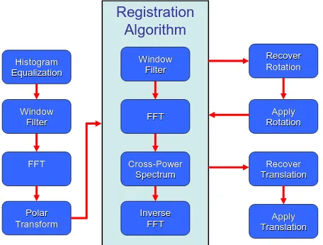
Medical Image Registration Using the Fourier Transform
Full text
Figure
Related documents
“Recently introduced CASA regulations are threatening the viability of industry and especially general aviation operations, with millions of dollars required to be invested for
• a comparison of the total cost (money and time) of maintenance training leading to the issue of a maintenance engineer licence (certification privileges) in Australia (under
The major goal of this project was to as- sist Kosovar refugees in an easier transi- tion of resettlement in Greater Victoria and becoming active and independent members of
Upon receipt of the supervisor’s consent for submission, and on the basis of full compliance with all other requirements for submission of the thesis for defense,
46 Rajan Narayan Dani Trade Wings Institute Of Management Ltd Director India [email protected] 47 Rajendra Prasad Airports Authority Of India Asst General Manager(CNS)
Since we discussed systems medicine as the future of medical genomics and healthcare in the inaugural issue of Genome Medicine [1], the field has witnessed trans-
All cases were further divided into the following five categories: (1) DHL/THL [ 9 ], which was defined as DLBCL with MYC and BCL2 and/or BCL6 rearrangements per the classic
