New Image Broadcasting based on Visual Cryptography
and Steganography
Dhiaa Alzubaydi
Associate professor, Department of Computer Science, University of
Al-Mustansiriyah
Dina R. Alshibani
Department of Computer Science, University of Al-Mustansiriyah
ABSTRACT
This paper presents a new security system by combining cryptographic and steganographic Technique. The main idea behind the present work is to divide the participants into different security levels, determining which participant will be able to decrypt the secret image, and which participant will not be able to decrypt the secret image. A modified idea of traditional visual cryptography with pixel expansion will be introduced to encrypt the data. The hiding method is based on hiding the pixel of the encrypted secret image in a colored cover by altering the DCT coefficients of the cover image. Before the hiding process Arnold transformation is performed on the cover image. The results show that the stego-image is closed related to the original cover image, with good impressibility.
General Terms
SecurityKeywords
Visual Cryptography, steganography, DCT, Arnold Transform, bit plane.
1.
INTRODUCTION
A. Visual Cryptography:
Visual cryptography is a special encryption, which provides information security, which uses uncomplicated algorithm unlike the complex, computationally exhaustive algorithms used in other techniques like conventional cryptography. This technique allows visual information (pictures, text, etc) to be encrypted in such a way that their decryption can be performed by the human visual system, without any complex cryptographic algorithms. This technique encrypts a secret image into shadows such that combining enough number of shadows reveals the secret image. Shadows are usually presented intransparencies [1].
B. Steganography:
Steganography is the art and science of script secreted messages in such a way that no one, apart from the sender and planned recipient, suspects the existence of the message. Images are the most popular cover objects used for Steganography. The properties like robustness and embedding capacity should be carefully considered when scheming a steganography algorithm [2].
2.
RELATED WORK:
In 2005 Jithesh and Dr. Kumar [3], suggest blending of both steganography and visual cryptography. The steganography technique used here is Discrete Cosine Transform Technique [DCT], the most reliable type of steganography technique and the new type of cryptography technique which is Visual Cryptograp hy. In 2008 Al-Anani et al. [4], presents a new technique to hide more than one colored encrypted image with encrypted data in a meaningful colored cover image. The
hidden secret images with their encrypted data can be extracted using different masks of the same cover image. One could retrieve the hidden information, which is customized to his own purposes relative to the mask designed for a particular purpose only. The same mask is used to encrypt both the secret data and the secret image in which data is hidden. This technique increases the level of security as well as the payload. In 2012 Surekha and Dr. Swamy [5], in this paper, a spatial domain image watermarking technique based on Visual Secret Sharing (VSS) and unique statistical properties is proposed. A key looking image is generated during watermark hiding process and is secretly registered with an arbitrator for verification during conflicts. Another random looking image is generated during watermark revelation stage and is combined with the existing one, to recover the watermark. This whole process is done without altering the image to be protected and hence the quality of the cover image is high. When compared with similar existing techniques, the proposed technique has two main advantages: Provides greater convenience in carrying and storing the intermediate images called shares; Provides high security.
3.
MATERIAL AND METHODS
3.1
Arnold Transform:
Arnold transform is selected as pre-treatment way for open image as it is uncomplicated and periodic. Arnold transform is a type of transform in the traversing theory, called as Arnold‟s cat mapping. Arnold transformation is defined as [6]:
𝑥𝑛 + 1 = 𝑥𝑛 + 𝑌𝑛 𝑚𝑜𝑑 𝑡 … .1
𝑌𝑛 + 1 = 𝑥𝑛 + 2𝑌𝑛 𝑚𝑜𝑑 𝑡 … .2
where xn,yn are the position of pixel in the orgin image, and n=1,2,3...n-1 and xn+1, yn+1 are the transformed position after arnold transform.
3.2
Discrete Cosine Transform (DCT):
Discrete cosine transform (DCT) is an important transform widely used in digital image processing. Large DCT coefficients are concentrated in the low frequency region; hence, it is known to have excellent energy compactness properties. The 2D discrete cosine transform of an image or 2D signal is defined as [7]:𝑐(𝑢, 𝑣) = 𝛼(𝑢)𝛼(𝑣) 𝑓 𝑖, 𝑗 cos 2 𝑥 + 1 𝑢𝜋 2𝑁 cos
2 𝑦 + 1 𝑣𝜋 2𝑁 … 3 𝑁−1
𝑦=0 𝑁−1 𝑥=0
𝜶 𝒖 𝜶(𝒗) = 𝟏
𝑵, 𝑢 = 0 𝟐 𝑵, 𝑢 ≠ 0
... 4
𝑓 𝑥, 𝑦 = 𝛼 𝑢 𝛼 𝑣 𝑐 𝑢, 𝑣 cos 2 𝑥 + 1 𝑢𝜋2𝑁 cos 2 𝑦 + 1 𝑣𝜋2𝑁 … .5
𝑁−1
𝑣=0 𝑁−1
𝑢=0 for u,v = 0,1,2,…,N −1.
4.
THE PROPOSED SYSTEM
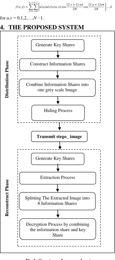
The proposed system supposes eight different participants connected to a dealer 𝐷 by a communication channel. The dealer 𝐷 is responsible for distributing information among the participants. Therefore, the proposed system is consisted of two phases: distribution phase (dealer side), and reconstruct phase (participant side). Figure 1 shows the block diagrams of the proposed system phases.
4.1
Distribution Phase (Dealer Side):
The distribution phase (dealer side) consists of two sub phases. These phases are: encryption phase and hiding phase.
4.1.1
Encryption Phase
:
The proposed VSSS Method is based on modified idea of VC, which depends on the codebook technique with pixel expansion of four-sub pixel. The encryption phase of the proposed method is consisted of sub Phases that described as follows:
i.
Key Distribution and Key Shares Generation
Process:
First, the dealer will generate eight different numbers (keys). One key per each user. Then distribute these keys to the participants. While storing a table of the User’s ID. These keys are used as a seed number to generate key shares in both sides (the dealer and participants) using the same function so the dealer can know what each Participant will have.
Pseudo Random Index Generator (PRIG) will be used for generating a sequence of random numbers; these random numbers will be used to construct the key share for each user. Pseudo Random Index Generator (PRIG) are usually constructed using the Linear Feedback Shift Registers (LFSR).A PRIG contains 𝑛 shift registers and it is initiated with a starting seed, which is usually transmitted through a secured channel for intended users only. The periodicity of such a random index generators is 2n-1.
After generating a sequence of random numbers, the proposed system will use the codebook in the Figure 2 to construct the Key share.
[image:2.595.54.276.69.569.2]
Fig 2: Visual Cryptography Codebook
ii.
Information Share Generation:
After the dealer generates the key share of each participant, then the priorities of each the participant will be determined by dividing them into the qualified and forbidden sets. Each participant in the qualified set will receive an information share, which is constructed from a particular secret image and participant key share, while each participant in the forbidden set will receive a black share.
In some cases, the dealer will constructed the eight information shares from the same secret image based on each participant key share, while in other cases the dealer will constructed each participant's share from a different secret image based on each participant's key share. The following matlab function is used to illustrate the steps of constructing the information share :
function Share2=info_shareShare1,secret_img) [r c]=size(secret_img);
for i=1:r for j=1:c
blk_sh1=Share1(2*i-1:2*i,2*j-1:2*j); if secret_img(i,j)==logical(1)
Share2(2*i-1:2*i,2*j-1:2*j)= blk_sh1; else
Share2(2*i-1:2*i,2*j-1:2*j)=~blk_sh1; end;
end; end;
iii.
Constructing the Grey Scale Image
After the construction of the eight information shares, these shares will be combined into one grey scale image by using the principle of bit plane slicing/recombination. The
following matlab function is used to explain how to
combine the eight information shares into one grey scale image :
Generate Key Shares
Construct Information Shares
Combine Information Shares into one grey scale Image
Hiding Process
Transmit stego_ image
Generate Key Shares
Extraction Process
Splitting The Extracted Image into 8 Information Shares
Decryption Process by combining the information share and key
[image:2.595.316.539.304.370.2]Share
Fig 1: Structure of proposed system
Distr
ib
u
tio
n
Ph
a
se
Re
co
n
str
u
ct
Ph
a
function gray_img=slice_stacking(bin_slices); [r c l]=size(bin_slices);
im_temp=zeros(r,c); for lvl=1:l
for i=1:r for j=1:c
temp(i,j)=temp(i,j)+bin_slices(i,j,lvl)*2^(lvl-1); end;
end; end;
gray_img=uint8(im_temp);
4.1.2 Hiding Process:
The second phase of the distribution phase is the hiding phase or embedding process. The inputs to the embedding process are the grey scale encrypted secret image of size (( 256 × 256). (The grey scale image which is the result from combining the eight binary information shares); and the cover image of size (512 × 512).
Before starting the embedding process, an Arnold Transform is applied to the cover image in order to increase the robustness of the proposed system against various attacks. The color cover image will be decomposed into the three bands Red, Green and Blue (RGB) an Arnold Transform is applied to each band. The steps of the hiding process is provided in the following matlab function:
function stego_image=dct_stego(cover, payload); [r c]=size(cover(:,:,1));
[r1 c1]=size(payload); temp=cover; for i=1:r/2
for j=1:c/2
rb=fix(dct2(cover(2*i-1:2*i,2*j-1:2*j,1))); gb=fix(dct2(cover(2*i-1:2*i,2*j-1:2*j,2))); bb=fix(dct2(cover(2*i-1:2*i,2*j-1:2*j,3))); pxl=dec2bin(payload(i,j),8);
% red band
if (mod((rb(1,2)),2)==0)&&(pxl(1)=='1') rb(1,2)=rb(1,2)+1;
elseif (mod((rb(1,2)),2)==1)&&(pxl(1)=='0') rb(1,2)=rb(1,2)-1;
end;
if (mod((rb(2,1)),2)==0)&&(pxl(2)=='1') rb(2,1)=rb(2,1)+1;
elseif (mod((rb(2,1)),2)==1)&&(pxl(2)=='0') rb(2,1)=rb(2,1)-1;
end;
if (mod((rb(2,2)),2)==0)&&(pxl(3)=='1') rb(2,2)=rb(2,2)+1;
elseif (mod((rb(2,2)),2)==1)&&(pxl(3)=='0') rb(2,2)=rb(2,2)-1;
end; % green band
if (mod((gb(1,2)),2)==0)&&(pxl(4)=='1') gb(1,2)=gb(1,2)+1;
elseif (mod((gb(1,2)),2)~=0)&&(pxl(4)=='0') gb(1,2)=gb(1,2)-1;
end;
if (mod((gb(2,1)),2)==0)&&(pxl(5)=='1') gb(2,1)=gb(2,1)+1;
elseif (mod((gb(2,1)),2)~=0)&&(pxl(5)=='0') gb(2,1)=gb(2,1)-1;
end;
if (mod((gb(2,2)),2)==0)&&(pxl(6)=='1')
gb(2,2)=gb(2,2)+1;
elseif (mod((gb(2,2)),2)~=0)&&(pxl(6)=='0') gb(2,2)=gb(2,2)-1;
end; % blue band
if (mod((bb(1,2)),2)==0)&&(pxl(7)=='1') bb(1,2)=bb(1,2)+1;
elseif (mod((bb(1,2)),2)~=0)&&(pxl(7)=='0') bb(1,2)=bb(1,2)-1;
end;
if (mod((bb(2,1)),2)==0)&&(pxl(8)=='1') bb(2,1)=bb(2,1)+1;
elseif (mod((bb(2,1)),2)~=0)&&(pxl(8)=='0') bb(2,1)=bb(2,1)-1;
end;
cover(2*i-1:2*i,2*j-1:2*j,1)=ceil(idct2(rb)); cover(2*i-1:2*i,2*j-1:2*j,2)=ceil(idct2(gb)); cover(2*i-1:2*i,2*j-1:2*j,3)=ceil(idct2(bb));
end; end;
stego_image=cover;
4.2 Reconstruct Phase (Participant Side):
The second phase of the proposed system is the reconstruct phase, which in turn is consisted of two processes: Extraction Process and Decryption Process.4.2.1 Extraction Process:
The step of extraction is similar to embedding steps but in reverse order. The extraction process steps are provided
in the following matlab function:
function rimage=recovery(stego_image); [r c]=size(stego_image(:,:,1));
for i=1:r/2 for j=1:c/2 pxl=uint8(0);
rb=round(dct2(stego_image(2*i-1:2*i,2*j-1:2*j,1))); gb=round(dct2(stego_image(2*i-1:2*i,2*j-1:2*j,2))); bb=round(dct2(stego_image(2*i-1:2*i,2*j-1:2*j,3))); % red band
if(mod((rb(1,2)),2)~=0), pxl=pxl+2^7; end; if(mod((rb(2,1)),2)~=0), pxl=pxl+2^6; end; if(mod((rb(2,2)),2)~=0), pxl=pxl+2^5; end; % green band
if(mod((gb(1,2)),2)~=0), pxl=pxl+2^4; end; if(mod((gb(2,1)),2)~=0), pxl=pxl+2^3; end; if(mod((gb(2,2)),2)~=0), pxl=pxl+2^2; end; % blue band
if(mod((bb(1,2)),2)~=0), pxl=pxl+2^1; end; if(mod((bb(2,1)),2)~=0), pxl=pxl+2^0; end; rimage(i,j)=pxl;
end; end;
4.2.2 Decryption Process:
Each participant will generate his own key share. After receiving his ID from the dealer. When the participant receives the stego_image extracting process will be performed on the stego-image in order to extract the embedded image. The extracted image will split into eight information shares. The splitting process of the grey scale image into eight information shares are described in the following matlab function:
im_temp=zeros(r,c,8); for lvl=1:8
for i=1:r for j=1:c
im_temp(i,j,lvl)=bitget(gray_img(i,j),lvl); end;
end; end;
bin_slice=logical(im_temp);
Thesecret image will be revealed by stacking the participant's key share and the extracted information share. the following matlab function explains the decryption process steps: function secret=recontract(Share1, Share2);
[r c]=size(Share1); for i=1:r/2 for j=1:c/2
blk_sh1=Share1(2*i-1:2*i,2*j-1:2*j); blk_sh2=Share2(2*i-1:2*i,2*j-1:2*j); if isequal(blk_sh1,blk_sh2) secret(i,j)=logical(1); else
secret(i,j)=logical(0); end;
end end;
5.
RESULT AND DISCUSSIONS
To retain the image quality, provide a stronger robustness and imperceptibility by using the DCT technique. The good visual quality of stego images (i.e. images with a secret image) is the very important property of steganographic system because it is difficult to detected by detectors. We used different image quality metrics in our experiment as shown in the Table 1 for more information return to [8,9].
[image:4.595.342.563.87.267.2]After applying the embedded and extracting process for the proposed method, PSNR,NCC, AD and SSIM measures have been used to assets the quality of the stego-image. Figures 3, 4 show the results for embedded and extraction steps where the test image used are color image for the cover of size 512 × 512 and 256 × 256 for secret image.
Table 1: image quality metrics
Quality
Metrics Formulas
Peak Signal to Noise
Ratio (PSNR)
𝑃𝑆𝑁𝑅 = 10 𝑙𝑜𝑔10𝑀𝑎𝑥 2
𝑀𝑆𝐸
Normalized Cross Correlation
(NCC)
NCC= 𝑥𝑖,𝑗∗ 𝑥′𝑖,𝑗 𝑀1(𝑥𝑖,𝑗 )2 𝑗 =1 𝑁 𝑖=1
𝑁 𝑗 =1 𝑀 𝑖=1
Average Difference
(AD)
AD= 𝑀𝑖=1 𝑁𝑗 =1 𝑥𝑖,𝑗− 𝑥′𝑖,𝑗 𝑀𝑁
Structural Similarity (SSIM)
SSIM= 𝜇 2𝜇𝑥 𝜇𝑦+𝐶1 (2𝜎𝑥𝑦+𝐶2)
𝑥 2+ 𝜇
𝑦 2+𝐶1 (𝜎
𝑥2+𝜎𝑦2+𝐶2)
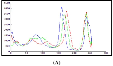
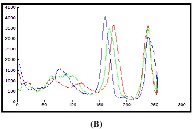
The first tool to assess the proposed hiding method is the histogram. The more the outlet histogram of an algorithm is close to the original image, the algorithm have more robustness against the statistical attacks. Figure 5 (A, B); shows that the histogram of the stego-image is similar to the histogram of the cover image. This mean the attacker cannot differentiate between the statics of stego-image and cover image.
[image:4.595.342.564.95.525.2](A)
Fig 4. Distribution phase
A. Key share B. Stego_image C. grey scale image D. spliting info shares E. Secret image
(A)
(B)
(C)
(D)
(E)
Fig 3. Distribution phase
A. Key share B. Secret image C.info shares D. combining info shares E. Cover image F.
Stego_image
(A)
(B)
(C)
[image:4.595.331.525.641.754.2](B)
[image:5.595.71.266.69.197.2]Fig 5. Histogram of (A) original image (B)stego-image
Table 2: The result of embedding image
PSNR NCC SSIM AD
57.9581 0.9991 0.9992 0.1113
58.1544 0.9992 0.9998 0.0966
57.9394 0.9992 0.9993 0.0944
58.0117 0.9992 0.9990 0.1090
58.0565 0.9992 0.9994 0.0980
It is clear from Table 2, that the PSNR value observed up to 55 dB. It shows that the proposed system is high imperceptibility, secure. Normalized Cross Correlation between the cover and stego-image observes nearly one this mean the stego-image has good correlation . SSIM are observed by nearly one. Average Difference values are observed in the range of 0.1113 to 0.1090. It also indicates less difference between cover and stego- image.
6.
CONCLUSIONS
Secret sharing schemes provide a good method of distributing a secret among a group of people with the requirement that a certain number of the participants need to recover the secret. The proposed system provides two levels of security to the data being transmitted. That is the intruders cannot easily break the system. Even if they realize the existence of a secret data, they cannot easily recognize the data, since data is hidden in two ways. This system overcomes the demerits of using single level of hiding. That is either using cryptography or steganography. Moreover, one more thing to add is it requires only the computation time of single level hiding, because visual cryptography requires no computation to decrypt the information. Using of DCT Transform provides good extracted secret image. The degree of degradation in the cover image is very low.
7.
REFERENCES
[1] N.Chekuri, J.Bellampalli , “ Region Incrementing Visual Cryptography” ,Bookman International Journal of Electrical & Electronics Engineering, Vol. 1 No. 1 Sep. 2012 .ISSN No. 2319-4294 © Bookman International Journals.
[2] O. Deshmukh, S. Sonavane," Multi-Share Crypt-Stego Authentication System ", IJCSMC, Vol. 2, Issue. 2, February 2013, pg.80 – 90.
[3] JITHESH K, Dr. A.V.S. KUMAR. “Multi- Layer Information Hiding-A Blend Of Steganography And Visual Cryptography”. Journal of Theoretical and Applied Information Technology, © 2005 - 2010 JATIT & LLS. All rights reserved.
[4] A.M. Anani, M.H. Abdallah, R.A. Dallah, R.I. Al-Khalid, “ Multimedia Multilevel Hiding Technique” , European Journal of Scientific Research , ISSN 1450-216X Vol.24 No.1 (2008), pp.42-54© EuroJournals Publishing, Inc. 2008.
[5] B. Surekha and Dr. G. N. Swamy," Visual Secret Sharing Based Digital Image Watermarking ", IJCSI International Journal of Computer Science Issues, Vol. 9, Issue 3, No 2, May 2012.
[6] M. Prasath, D. Sharmiladevi, " DIGITAL IMAGE
HIDING USING TRANSFORMATION
TECHNIQUES", nternational Journal of Communications and Engineering ,Volume 05– No.5, Issue: 03 March 2012.
[7] V.Naidu,” Discrete Cosine Transform based Image Fusion Techniques”, Journal of Communication, Navigation and Signal Processing (January 2012) ,Vol. 1, No. 1, pp. 35-45.
[8] S. Bhattacharyya, G. Sanyal " A Robust Image Steganography using DWT Difference Modulation (DWTDM )", I. J. Computer Network and Information Security, 2012, 7, 27-40 Published Online July 2012 in MECS (http://www.mecs-press.org/) DOI: 10.5815/ijcnis.2012.07.04.