LTE Heterogeneous Network: A Case Study
Aubida.A.Jasim and Sami A. Mawjoud
Electrical Engineering Department University of Mosul, Mosul, Iraq
ABSTRACT
Long terms evolution (LTE) allows using new and wider spectrum up to 20MHz with high data rates and lower latency. This paper provides analysis of the concept of heterogeneous networks as compared to homogenous networks on a realistic scenario of Mosul city and discusses the need for an alternative deployment model and topology to enhance the performance of network. It is clearly demonstrating the need for using inter-cell interference coordination (ICIC) methods to achieve a good performance for network especially at the cell edge. Heterogeneous network enables flexible and low-cost deployments and it has attractive solution for non-uniform traffic distribution or needed a special service in hot-spot.
Keywords: Homogenous Networks , LTE , Capacity , ICIC
1. Introduction
Wireless networks have experienced flying growth in the past twenty years. The trend is expected to continue with the deployment of Mobile Broad-Band (MBB) services. In the coming five to ten years, it is foreseen to have hundreds or even thousands times of the current mobile network capacity. The straightforward way to increase capacity is to apply the new spectrum to telecommunications. However, full application of new spectrum will happen in a long-term, so how to effectively use the allocated spectrum is the most urgent task [1].
An elementary and well-known strategy to increase the capacity of a cellular network is to reduce the cell size. The underlying effect is to further increase the frequency reuse, also known as “cell-splitting gain”. For cost optimization different types of eNBs are used for different purposes, e.g. large-scale eNBs for basic coverage, smaller eNBs to fill coverage holes or to improve capacity in hot-zones or at the boundaries between large-scale eNBs’ coverage areas, and possibly even smaller eNBs for indoor coverage. LTE is designed for a frequency reuse of 1, meaning that every base station uses the whole system bandwidth for transmission and there is no frequency planning among cells to cope with interference from neighbouring cells. Hence, LTE macro-cell deployments experience heavy interference at the boundaries of the cells. Placing a new eNB between macro-cells would boost the SINR levels for users located there, achieving a more uniform user satisfaction and overcoming link-budget constraints [2].
Picocells are regular eNBs with the only difference of having lower transmitted power than traditional macro cells. They are, typically, equipped with omni-directional antennas, i.e., not sectorized, and are deployed indoors or outdoors often in a planned (hot-spot) manner. Their transmit power ranges from 250 mW to approximately 2 W for outdoor deployments, while it is typically 100 mW or less for indoor deployments[3].
1.1Traditional Network Deployment Approach
Current wireless cellular networks are typically deployed as homogeneous networks using a macro-centric planning process. A homogeneous cellular system is a network of base stations in a planned layout and a collection of user terminals, in which all the base stations have similar transmit power levels, antenna patterns, receiver noise floors and similar backhaul connectivity to the (packet) data network. Moreover, all base stations offer unrestricted access to user terminals in the network, and serve roughly the same number of user terminals, all of which carry similar data flows with similar QoS requirements. The locations of the macro base stations are carefully chosen through network planning, and the base station settings are properly configured to maximize the coverage and control the interference between base stations. As the traffic demand grows and the RF environment changes, the network relies on cell splitting or additional carriers to overcome capacity and link budget limitations and maintain uniform user experience. However, this deployment process is complex and iterative. Moreover, site acquisition for macro base stations with towers becomes more difficult in dense urban areas. A more flexible deployment model is needed for operators to improve broadband user experience in a ubiquitous and cost-effective way [4].
1.2An
Alternate
Approach
Using
Heterogeneous Network
flexibility in backhaul where wire linebackhaul is unavailable or not economical[4].
Figure (1) Heterogeneous Network utilizing mix of macro, Pico, Femto and relay base stations [2].
In a homogeneous network, each mobile terminal is served by the base stations with the strongest signal strength, while the unwanted signals received from other base stations are usually treated as interference. In a heterogeneous network, such principles can lead to significantly suboptimal performance. In such systems, smarter resource coordination among base stations, better server selection strategies and more advanced techniques for efficient interference management can provide substantial gains in throughput and user experience as compared to a conventional approach of deploying cellular network infrastructure [4].In addition, heterogeneous networks based on different access technologies, where macro network is based on a cellular technology and low power access points are based on WLAN have also been studied in literature [3][5][6]. Reduced cost is one of the main drivers for the adoption of femto cells. It was shown in [7] that in urban areas a combination of publicly accessible home base stations or femto cells (randomly deployed by the end user), and macrocells deployed by an operator for area coverage in a planned manner, can result in significant reductions (up to 70 percent in the investigated scenario) of the total annual network costs compared to a pure macro-cellular network deployment. If a wired backhaul is not available, relay nodes can be deployed where the air interface spectrum is used for backhaul connectivity and to provide access to terminals .In this case, the relay node appears as user equipment (UE) to the macro base station and as a regular base station to the UE it serves[3] [8].
2. DEPLOYMENT SCENARIO
This paper mainly focuses on co-channel deployment approach because LTE is designed for frequency reuse 1 which meaning that every sector of base station uses the same allocated system bandwidth which attractive from cost-effect matter but this approach need an interference coordination because using the same channel for Marco cell and Pico or Femto cell makes a heavy interference at cells boundaries. Straightforward co-channel deployment of low-power nodes has its own challenges. The introduction of low-power nodes in a macro network creates imbalance between uplink and downlink coverage. Due to larger transmit power of the macro base station, the handover boundary is shifted closer to the low-power node, which can lead to severe uplink interference problems as UE units served by macro base stations create strong interference to the low-power nodes. Given the relatively small footprint of low-power nodes, even in the case of the most optimized placement, low-power nodes may become underutilized due to geographic changes in data
traffic demand. The performance of a mixed deployment of macro, pico, and open femto cells was evaluated in[3] [9][ 10].
3. Inter-Cell Interference Coordination
(ICIC)
In 4G networks, new physical layer design allows for flexible time and frequency resource partitioning. This added flexibility enables macro- and femto/picocells to assign different time-frequency resource blocks within a carrier or different carriers (if available) to their respective UE. This is one of the intercell interference coordination (ICIC) techniques that can be used on the downlink to mitigate data interference [3][11][12]. With additional complexity, joint processing of serving and interfering base station signals could further improve the performance of heterogeneous networks[3] [13][ 14], but these techniques require further study for the scenarios commonly seen in practice.
Inter-Cell Interference Coordination (ICIC) plays a vital role in heterogeneous networks. ICIC techniques in LTE are mostly limited to the frequency domain, e.g. only partial use of resources in frequency direction and/or adaptation of power levels. Figure (2) shows an overview of a number of frequency partitioning methods. These ICIC methods describe basic rules on how a system performance boost can be achieved by managing the system bandwidth and transmit power. The following discussion will introduce general notions about frequency partitioning and the available options for LTE release 8/9 [2].
Figure (2) Different inter-cell interference coordination schemes [2].
3.1 Hard Frequency Reuse
[image:2.595.57.285.118.224.2] [image:2.595.318.549.413.554.2]3.2 Fractional Frequency Reuse (FFR)
In fractional frequency reuse, the available bandwidth is divided into segments, in which varying frequency reuse schemes can be utilized. Typically, the bandwidth is divided into two parts: the first part is allocated to the Cell Center Users (CCU) and the second part to the Cell Edge Users (CEU). As the CEU experience higher interference levels than the CCU, it is purposeful to use higher reuse factors for the CEUs than for the CCUs. In a typical fractional reuse scheme, reuse factors one and three are utilized in the cell center and the cell edge respectively. If the utilized reuse factors are higher than one, fractional reuse decreases the spectral efficiency of the network; however, not as much as hard frequency reuse. Therefore, the performance of fractional reuse can be seen as a compromise between the spectral efficiency and the cell edge performance. Fractional frequency reuse principle is illustrated in figure (2) [15].
3.3 Soft Frequency Reuse (SFR)
In a basic soft frequency reuse scheme all cells can utilize the whole available bandwidth, but for each cell an individual power spectrum has been defined. The power spectrums are chosen in a way, where the probability of overlapping high power transmission is small. With this method, the probability of adjacent cells utilizing the same resource block does not decrease, but the effects of a collision are smaller. As a result, the interference decreases effectively both in UL and DL. As a major benefit of the soft frequency reuse, the whole bandwidth can be utilized in all cells leading to a high spectral efficiency. Soft frequency reuse is illustrated in figure (2) [15].
4. Case Study Scenario
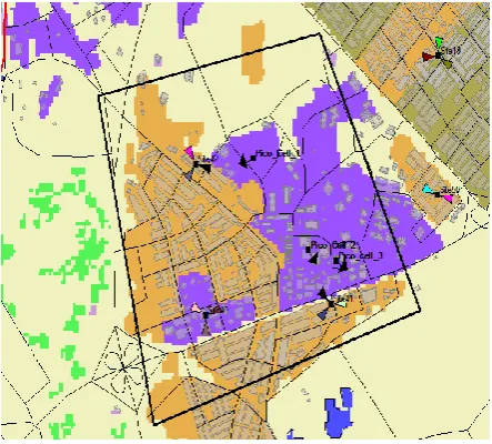
The urban scenario of Mosul city has been chosen the area of approximately 4.5 Km2. A radio network planning tool has
been done to place the base stations (Marco-cells) at best possible locations with three Pico-cell located according possible traffic demand asshown in figure (3) and the parameters configurations (antenna height , Downtilt angle azimuth,etc.) of BSs are optimized by using an optimization algorithm.
Figure (3) map of Mosul city showing BSs locations.
4.1 Propagation Model
Propagation is based on the imported 30m resolution raster map with building map.the practical calibration of Cost-Hata propagation model for urban area has been donethe calibration results are the mean error=-2.4 dB and the mean standard deviation=7.7 dB as shown in figure (4).
Figure (4) Received Signal strength of measurement and prediction
The COST-Hata-Model is formulated as [16]:
Where, C= 0 dB for medium cities and suburban areas and 3 dB for metropolitan areas
L = Median path loss. Unit: Decibel (dB)
f = Frequency of Transmission. Unit: Megahertz (MHz)
hB= Base Station Antenna effective height. Unit: Meter (m)
d = Link distance. Unit: Kilometer (km)
hR = Mobile Station Antenna effective height. Unit: Meter (m)
a (hR) = Mobile station Antenna height correction factor as described in the Hata Model for Urban Areas.
Table (1) LTE Simulation Assumption
Total network elements:6 eNBs Monitored network elements : 3 Marco-cells, 3 Pico-cells
Network layout
2100 MHz
System frequency
10 MHz
System bandwidth
50
Number of PRBs
Ruse 1,FFR,SFR
Frequency planning
1200m
Macro-cell Inter-site distance
Calibrated Cost 231-Hata
Propagation loss model
… (1)
[image:3.595.320.540.151.282.2] [image:3.595.55.277.521.721.2] [image:3.595.303.541.599.760.2]43dBm for Marco cell,24dBm for Pico-cell
TX power
SISO
Antenna Techniques
65o for Marco-cell, Omni for Pico-cell
Horizontal HPBW
6.8o
Vertical HPBW
0.5 dB
TX cable loss
0 dB
RX antenna gain
0 dB
RX body loss
7 dB
RX noise figure
Proportional Fair
Scheduling
Pedestrian
UE speed
4.2 Traffic Model &Users Distribution
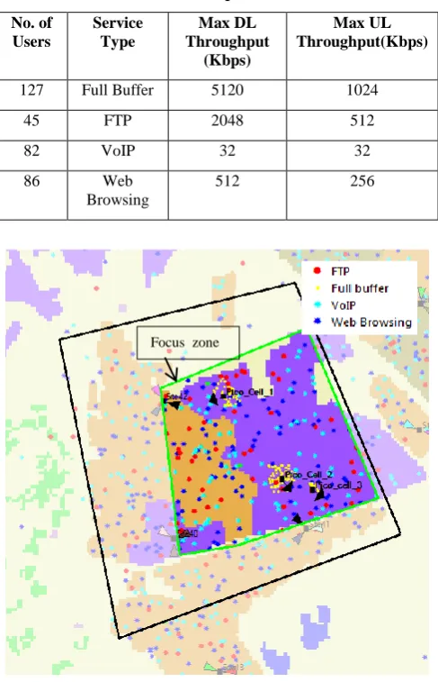
[image:4.595.44.279.70.262.2]Total numbers of users are 340 distributed on 2 km2of area (focus zone) with different services using Monte Carlo simulation as shown in figure (5) with special service (full buffer) for Pico-cell users.
Table 2 illustrates traffic parameters services.
No. of Users
Service Type
Max DL Throughput
(Kbps)
Max UL Throughput(Kbps)
127 Full Buffer 5120 1024
45 FTP 2048 512
82 VoIP 32 32
86 Web
Browsing
512 256
Figure (5) .traffic map and users distribution.
5. Simulation Results
In this section we present a simulation for LTE system performance by using LTE radio network planning that utilizes Monte Carlo technique for capacity and coverage analyses for this purpose two scenarios are evaluated the first scenario correspond to Marco-cells deployment (homogenous network) with 10Mhz bandwidth and frequency ruse 1 planning . The second scenario adds a Pico-cells deployment (heterogeneous network) with 10 Mhz for marco and pico cells and frequency ruse 1 planning. The final section includes a proposed model for interference management between Marco and Pico-cells.The frequency allocation among macro and pico cells is critical to heterogeneous network the following approaches:
(1) "Co-channel allocation: macro cells as well as pico cells share the same entire frequency band.
(2) Orthogonal frequency allocation: macro cells are assigned to a part of the whole frequency resource, and pico cell would use the remaining part, thus, frequency resource between macro cell and local cell is not overlapped.
(3) Overlapped frequency allocation: Frequency resource between marco cells and pico cells is overlapped partially. For example, Marco cells are assigned to a part of the whole frequency resource, while the pico cells occupy the whole frequency resource, and vice versa [1]".
(4) (proposed) a combination from FFR and SFR to get a model of ICIC have the advantage of FFR at cell edge and the advantage SFR at center of cell as illustrated in table 3 and figure (7) .
The corresponding examples of the first three frequency allocation Approaches with 10MHz whole bandwidth are shown in Figure (6) [1].
Figure (6)Heterogeneous network channel deployments[1]
Figure (7) division of 50 PRB (10 MHz)bandwidth.
[image:4.595.51.295.355.734.2] [image:4.595.319.551.472.587.2]Table (3) frequency allocation for cells.
Cell ICIC Cell center freq. allocation
Cell Edge freq. allocation
Marco-cell_1 FFR f1 f2
Marco-cell_2 FFR f1 f3
Marco-cell_3 FFR f1 f4
Pico-cell_1 SFR f1,f2,f3 f4
Pico-cell_2 SFR f1,f3,f4 f2
Pico-cell_3 SFR f1,f2,f4 f3
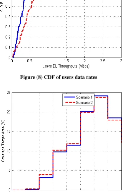
The first observation is the improvement of users throughput (capacity) achieved by add a pico-cells to marco-cell (scenario 2) as compare with scenario 1 (marco-cells only) as shown in figure (8).in figure (9) it is observed the slightly improvement of signal received strength (coverage).
Figure (8) CDF of users data rates
Figure (9) PDF of received signal power
As shown in figure (10) the remarkable improvement of pico-cells throughput when using the proposed model of ICIC as compared with the first three approaches of frequency allocation and have approximately gain equal (5%-15%) more than other .in figure (11) the 10% of CDF which represents the SINR of cell edge it is clearly observe the improvement of SINR which lead to enhancement the data rate for cell edge users.
Figure (10) Pico-cell throughput
Figure (11) CDF of SINR
6. CONCLUSIONS
[image:5.595.48.296.104.234.2] [image:5.595.330.530.175.381.2] [image:5.595.328.533.178.604.2] [image:5.595.67.277.321.522.2] [image:5.595.67.280.400.727.2] [image:5.595.331.536.410.616.2]7. REFERENCES
[1] Wan Lei and Wu Hai" Heterogeneous Network in LTE-Advanced System" IEEE International Conference on Communication Systems, 2010 , pp. 156-160.
[2] V. Pauli, J. D. Naranjo and E. Seidel, Heterogenous LTE Networks and Inter-Cell Interference Coordination, NomorRecearch GmbH, 2010.
[3] QUALCOMM INC. ALEKSANDAR DAMNJANOVIC and JUAN MONTOJO "A SURVEY ON 3GPP HETEROGENEOUS NETWORKS" IEEE Wireless Communications,, 2011 , Vol. 18 , No. 3 , pp. 10-20. [4] Qualcomm Research "LTE Advanced: Heterogeneous
Networks" Jan 2011 available at http://www.qualcomm.com/media/documents
[5] M. Coupechoux, Kelif, and Godlewski, “Network Controlled Joint Radio Resource Management for Heterogeneous Networks,” IEEE 2008.
[6] Song,. Jiang, and Zhuang, “Performance Analysis of the WLAN-First Scheme in Cellular/WLAN Interworking,” IEEE Trans. May 2007.
[7] Claussen, and L. G. Samuel, “Financial Analysis of a Pico-Cellular Home Network Deployment,” IEEE ICC 2007.
[8] BouSaleh “Comparison of Relay and Pico eNB Deployments in LTE-Advanced,” IEEE 2009.
[9] Nihtila and Haikola, “HSDPA Performance with Dual Stream MIMO in a Combined Macro-Femto Cell Network,” IEEE 2010.
[10] Karimi “Evolution Towards Dynamic Spectrum Sharing in Mobile Communications,” IEEE PIMRC2006.
[11] Boudreau “Interference Coordination and Cancellation bfor 4G Networks,” IEEE Commun. March., 2009. [12] Khandekar., “LTE-Advanced: Heterogeneous
Networks,” European Wireless Conf. 2010.
[13] Simeone, and S. Shamai , “Robust Transmission and Interference Management For Femtocells with Unreliable Network Access,” IEEE ,Dec. 2010.
[14] Annapureddy. “http://www.ieee-ctw.org/2010/ mon/Gorokhov.pdf,” 2010 IEEE Commun. TheoryWksp., Cancun, Mexico, 2010.
[15] LasseLaine "Performance Management of 3rd Generation Partnership Project Long Term Evolution" M.Sc. Thesis, School of Electrical Engineering Department of Communications and Networking, AALTO UNIVERSITY ,Sep 2011
![Figure (2) Different inter-cell interference coordination schemes [2].](https://thumb-us.123doks.com/thumbv2/123dok_us/8092432.785190/2.595.57.285.118.224/figure-different-inter-cell-interference-coordination-schemes.webp)