Improved Performance Evaluation of Frequency Hopped
Spread Spectrum using QAM/FSK Modulation
Techniques
Rajiv Mohan David
Research Scholar and Assistant Professor-Senior Grade, Dept. of Electronicsand Communication Engineering. Manipal Institute of Technology,Manipal
University,Manipal.
Kumara Shama
Professor, Dept. Of Electronicsand Communication Engineering Manipal Institute of Technology, Manipal
University, Manipal, Karnataka,India.
K. Prabhakar Nayak
Professor, Dept. Of Electronicsand Communication Engineering Manipal Institute of Technology, Manipal
University, Manipal, Karnataka,India
ABSTRACT
A brief theoretical foundation has been provided that expands upon QAM and FSK modulation in the application of Frequency Hopped spread spectrum systems. This paper mainly focuses on the Bit Error Estimation in Frequency Hop Spread Spectrum System using Quadrature Amplitude modulation and Frequency shift keying which are used in defense applications. The main aim here is to calculate the bit error performance of a frequency hopping spread spectrum model in the presence of AWGN channel. This paper provides a systematic approach for evaluating the performance of FHSS operating with coherent M-ary FSK demodulation. There have been investigations into the frequency hop spread spectrum systems employing different modulation schemes to decrease the bit error ratios. There has been much work done on computing BER of FHSS systems with error control coding using industry standard convolutional coding.
Keywords
Frequency Hopped spread spectrum,FSK,QAM.
1.
INTRODUCTION AND LITERATURE
REVIEW.
Spread spectrum techniques can be very useful to overcome the communication problems like security and efficient usage of power. In this technique, the information signal to be transmitted is multiplied by the PN code (This is the general case and it can be any kind of sequence.),called spreading code signal. The signal which is obtained after the multiplication of PN code is called spread signal which is then transmitted. The receiving side acquires the transmitted signal, which is then multiplied by a same spreading code signal, so that the original signal is recovered. It can be seen that the required signal gets multiplied twice but the interference gets multiplied only once, which will reduce the interference and that will be a great protection against jamming. The main property of the spreading signal is the bandwidth expansion factor (Be=Width/Data rate), which is much greater than unity, that means the redundancy involved in the spread signal can easily overcome the interference The processing gain is used to measure the amount of the improvement of system with the use of spread spectrum system. Processing gain is the difference between the performance of the system using spread spectrum techniques and the performance of the system which is not using the
spread spectrum techniques processing gain also defined as the ratio of spread signal bandwidth (WSS)to the information
rate.
Spread Spectrum modulation techniques are defined as the technique in which the bandwidth of the transmitted signal is much greater than the bandwidth of the original message, and the bandwidth of the transmitted signal is determined by the message to be trans Spread spectrum system has now come up as a promising digital technology for mobile systems, with the innovation of VLSI technology. In this technique, Linear Feedback Shift Register (LFSR) is the basic unit or element, which generates Maximal length PN sequence or m- sequence. Linear Feedback Shift Register represented by a primitive polynomial. In Spread Spectrum system each user is assigned a pseudo noise sequence (PN) for the purpose of spreading as well as de-spreading. Thus PN-sequence generation is considered to be the heart of SS system. The maximal length PN-sequence (m-sequence) is the best-known sequence whose length is equal to its period. Various PN-codes can be generated using Linear Feedback Shift register (LFSR).The generator polynomial provides the necessary feedback taps for the LFSR circuit.
allowing bandwidth sharing without any loss of information [4].
Spread Spectrum (SS) [6-10] is termed as a means of transmission in which the signal occupies bandwidth much in excess of the minimum necessary to send the information. It can be perfectly reconstructed for the intended receiver and it seems to be random-like for others. This randomness of the sequence should satisfy the properties like balance, run and autocorrelation. While the spread Spectrum naturally means that each transmission utilizes a large amount of spectrum, so that a considerable number of users might share the same spectral band. A distinct code has been assigned for each transmitter. So there exists a possibility of high interference between the users when they are very close to each other. The interference may be intentional, as in military communications, or it may be no intentional as in a spectral overlay system [11]. In any case, the receiver achieves higher signal to noise ratios (SNR’s) at the decision device input if an interference rejection filter is used before dispreading [12]. The rejection filter is usually adaptive and relies on the pseudo-white properties of the spread spectrum signal [13]. Spread spectrum communication has advantages of strong anti-interference ability, good security, high-speed rate, being easy to realize CDMA and less interference to other narrowband systems in the same band[14]. The performance of wireless communication system is limited by fading and jamming, the former arises from signals multipath propagation, while the latter results from the reuse of frequencies.[15].It is widely used in military and civilian applications for its excellent performances and the spreading codes has high autocorrelation and low cross correlation properties.[16-18].
2.
FREQUENCY HOPPED
TRANSRECEIVER
In a Frequency- hopped (FH) spread spectrum communication system the available channel bandwidth is subdivided into a large number of contiguous frequency slots. In any signalling interval, the transmitted signal occupies one or more of the available frequency slots. The selection of frequency slot(s) in each signalling interval is made according to the output from a PN generator. The modulation technique which is used in FHSS is M-ary FSK and QAM along with convolution coder . The resulting FSK signal is translated in frequency by an amount that is determined by the output sequence from the PN generator, which, in turn is used to select a frequency that is synthesized by the frequency synthesizer. This frequency is mixed with the output of the modulator and the resultant frequency-translated signal is transmitted over the channel. The m bits from the PN generator may be used to specify 2m-1 possible frequency translations. The modulated signal is transmitted over the AWGN channel. At the receiver, we have an identical PN generator, synchronized, with the receiver signal, which is used to control the output of the frequency synthesizer. Thus, the pseudorandom frequency translation introduced at the transmitter is removed at the receiver by mixing the synthesizer output with the received signal. The resultant signal is demodulated by means of an M- FSK demodulator. A signal for maintaining synchronism of the PN generator with the frequency –translated received signal is
2.1
Mathematical Interpretation
Transmitting two signals by modulating them with QAM, the transmitted signal will be of the form
where I(t) and Q(t) are the modulating signals and f0 is the
carrier frequency.At the receiver, these two modulating signals can be demodulated using a coherent demodulator. Such a receiver multiplies the received signal separately with both a cosine and sine signal to produce the received estimates of I(t) and Q(t) respectively. Because of the orthogonality property of the carrier signals, it is possible to detect the modulating signals independently.
In the ideal case I(t) is demodulated by multiplying the transmitted signal with a cosine signal:
Using standard trigonometric identities, we can write it as:
Low-pass filtering ri(t) removes the high frequency terms (containing 4πf0t), leaving only the I(t) term. This filtered
signal is unaffected by Q(t), showing that the in-phase component can be received independently of the quadrature component. Similarly, we may multiply s(t) by a sine wave and then low-pass filter to extract Q(t).
Frequency hopping systems change the carrier frequency at a rate comparable with (or slower than) the information rate which used to transmit .frequency hopping can be done coherently or non -coherently. For a coherent FH system the output of the frequency’s written as [5]
)
-n 2p(t-nTc)cos(ωnt φn
(t) T
h
where p (t) represents pulse of duration TC, with unit
amplitude starting at time zero , ωn andФn are the radian
frequency and phase during the nth frequency hop interval .The frequency wn is taken from a set of 2k frequencies. In
FH system k-bits of the spreading code is used . Transmitted signal is the data modulated carrier whose frequency changes to a new carrier frequency ie (wn+ wo)
for each FH chip [5]
components freq sum ) -n n φ t n )cos(ω c nT -2p(t (t) d s (t) t s
Power spectrum of the transmitted signal is sum frequency term of the convolution of Sd(f ) and Sh(f), where Sd(f) is the
power spectral density of the data modulated carrier Sh(f) be
the power spectral density of the carrier hop hT(t), these two
are independent . The signal hT(t) may or may not be periodic.
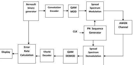
Fig 1. FHSS / QAM with Viterbi decoder
3.
RESULTS AND DISCUSSIONS
[image:3.595.48.564.96.349.2].
Fig 2. QAM with AWGN
Fig 3. QAM with FHSS without FEC using PN sequence generator
Bernoulli binary generator
QAM
MOD
Spread Spectrum Modulation
AWGN
Channel
Spread Spectrum Demodulation Convolution
Encoder
QAM
DEMOD
ViterbiDecoder
Error
Rate
Calculation
Display
[image:3.595.315.538.435.612.2]Fig 4. QAM with FHSS using PN sequence generator with FEC
Fig 5. BER of FHSS/FSK with PN sequence in AWGN channel
A model of gray coded 16-QAM with AWGN Channel has been designed and the BER curve for this has been simulated as shown in Fig2. The result is close to the theoretically expected plot of BER vs. Eb/No of an ideal 16-QAM system without error coding. Fig 3. demonstrates the BER
analysis data for the Maximal length code is plotted in Fig.5.From the simulation results it can be observed that as the Signal to noise ratio increases the Bit error rate attains a negligible value .
4.
CONCLUSION
The objective of this investigation was met successfully and various plots generated supported the conclusion that the generated models were close to and in cases better than the ideal performance expected. The spread spectrum process as evident is an effective way of transmission with lesser bit error ratio and the FEC employed as a Convolution/Viterbi coding is also productive in obtaining a lowered BER of the FHSS/QAM system. Forward Error correction helps in reducing the inherent disadvantage of a QAM system that is high signal to noise ratio requirement for a small change in BER. This paper also demonstrates the development and analysis of Frequency- Hopped Spread Spectrum (FH/SS) transceiver using M-FSK works under the influence of an Additive White Gaussian Noise (AWGN) channel were simulated.
5.
REFERENCES
[1] R. L. Pickholtz, D. L. Schilling and L. B. Milstein, Theory of spread spectrum communications- A tutorial,‖ IEEE Trans. Commun., vol. COM-30, no. 5, May 1982 [2] Raymond L. Pickholtz, ―Theory of spread spectrum
communication – A tutorial‖, IEEE Trans. Communication, vol. 30, No.5, May 1982
[3] B. Sklar, Digital Communications: Fundamentals and Applications, 2nd Ed., Prentice Hall, 2001.
[4] R. L. Peterson, R. E. Ziemer, and D. E. Borth, Introduction to Spread-Spectrum Communications. Englewood Cliffs, NJ: Prentice- Hall, 1995.
[5] N.B chakrabarti, A. K. Datta, “introduction to the principles of digital communication", New Age Publishers, 2007.
[6] Erik Storm, Tony Ottosson, Arne Svensson, “An introduction to spread spectrum systems”, Department of signals and systems, Chalmers university of technology, Sweden, 2002.
[7] Raymond L. PICKHOLTZ, “Theory of spread spectrum communication – A tutorial”, IEEE Trans. Communication, vol. 30, No.5, May 1982.
[8] Ryuji Kohno, Reuven Meidan, and Laurence B. Milstein, “Spread Spectrum Access Methods for Wireless Communications”, IEEE Communication magazine, January 1995.
[9] Yong Luo, “Spread Spectrum Ranging System – Analysis and Simulation”, Master Thesis in Electronic systems engineering – University of Regina, Saskatchewan, March 1998.
[10]D. Schilling et al., “spread spectrum for commercial communications,” IEEE commun. Soc. Mag., pp. 66-79, Apr. 1991.
[11]J. Ketchum and J. Prokis, “Adaptive algorithms for estimating and suppressing narrowband interference in PN spread spectrum systems,” IEEE trans. Commun., vol. COM-30, pp. 913-923, May 1982.
[image:4.595.54.287.333.590.2]“Design of A Spread Spectrum Communication System Based on DSP”, Proceedings of the 2011 IEEE International Conference on Cyber Technology in Automation, Control, and Intelligent Systems March 20-23, 2011, Kunming, China.
[15]Yu Zhang, Xuehe Zheng,Sen Yang,Ning Zhong, Kuangyi Qiao,Jihua Lu,” Modeling and Performance Analysis of Frequency Hopping Spread Spectrum Communication System “IEEE Xplore Digital Library,2010.
[16]Rajiv Mohan David,Kumara Shama and K.Prabhakar Nayak “Efficient Synchronization and Data detection for DS-CDMA Applications International Journal of Computer and ElectronicsEngineering,ISSN:0975-4202(Vol.3No.2011),pp-251-261.
[17]Rajiv Mohan David,Kumara Shama , K.Prabhakar Nayakand Vasanth Maiya “Design of spreading codes with increased performance in correlation property” International Journal of Applied Engineering Research.,ISSN:0973-4562(Vol.5 No.6 2010),pp-997-1008.
[18]Rajiv Mohan David ,Kumara Shama, K.Prabhakar Nayak “Digital Filter bank Implementation using Multirate Techniques for Spreading codes and rate transition techniques in spread spectrum”International Research Journal of signal Processing, ISSN:2249-6505(Volume3,Issue1,February 2012),pp:445-453.
6.
AUTHORS PROFILE
Rajiv Mohan David received his B.E degree in 1998 in Electronics and Communication Engineering from Bharathiar University, M.B.A degree in 2000 from University of Madras and M.E degree in Applied Electronics in 2001 from Bharathiar University. Currently he is pursuing his Ph.D degree in the area of Spread Spectrum Communication. He is
currently working as Assistant Professor-Senior Grade in in the Department of Electronics and Communication Engineering at Manipal Institute of Technology,Manipal,India and has a total of 10 years of teaching experience. He has published research papers in journals and conferences.
Kumara Shama received his B.E. degree in 1987 in Electronics and Communication Engineering and M.Tech. degree in 1992 in Digital Electronics and Advanced Communication, both from Mangalore University, India. He obtained his Ph.D Degree from Manipal University, Manipal in the year 2007 in the area of Speech Processing. Since 1987 he has been with Manipal Institute of Technology, Manipal University, Manipal, India, where he is currently a Professor in the Department of Electronics and Communication Engineering and has a total of 25 years of teaching experience .His research interests include Speech Processing, Digital Communication and Digital Signal Processing. He has published many Research papers in various journals and conferences.