FPGA Implementation of the CORDIC Algorithm for
Fingerprints Recognition Systems
Nihel Neji, Anis Boudabous, Wajdi Kharrat, Nouri Masmoudi
University of Sfax, Electronics and Information Technology Laboratory, National School of Engineering, BP W 3038, Sfax, TUNISIA
ABSTRACT
In this paper, we propose a low-cost sequential architecture for the implementation of CORDIC algorithm in two computation modes. It suited for serial operation that performs conversion between polar and rectangular coordinate systems, essentially sin/cos, sinh/cosh and arctan computation. The design targets real time application of fingerprint recognition. We present a VHDL description of CORDIC algorithm. To reduce iteration delay, we used some combinatory blocks. Fixed point arithmetic was considered. To valid our conception and its CORDIC accuracy, we present relative error calculated in convergence range for some trigonometric and hyperbolic functions. All measurements show an enhancement compared with our previous work. The architecture was implemented and tested. The contribution of the paper includes the CORDIC design flow.
Keywords
CORDIC algorithm, fingerprint, VHDL, hardware, FPGA
1.
INTRODUCTION
Fingerprint recognition systems are the focus of research and development. They allow new types of services universally available to consumers and for industrial applications. This paper is based on a project which aims to develop a fingerprint recognition system. The most difficult to implement functional blocks is Fast Fourier Transform (FFT) processor. A Coordinate Rotation Digital Computer offers an elegant way of its implementation[1]. It can be applied to FPGA applications, in which the rotation angles are usually known, the twiddle factor in FFT and kernel components in other sinusoidal transforms [2],[3]. The CORDIC scheme has been applied to the FFT processor design and found to result in significant hardware reduction in the implementation of twiddle-factor multiplications.
In this work, we exploit the FPGA circuit capacity to design a reconfigurable architecture for computation of elementary functions such as sine, cosines, exponential and arctangent using this algorithm. We focus on polynomial approximations with fixed coefficients and powers of x to search errors over a bounded interval. Then, we deal with CORDIC evaluation to calculate outputs in fixed-point-format. The obtained average of error is close to the error of polynomial approximations. This makes our method an attractive solution for signal processing applications. The remaining paper is organized as follows. Section 2 represents the previous work which proposed different types of CORDIC architectures. The CORDIC algorithm is described in Section 3. Section 4 presents the proposed architecture for rotation and mode derived from the algorithm specification.
Finally, in section 5 the results of the implementation are reported and the performance comparison of proposed architecture with the other architectures available in the literature is explained. The conclusion is drawn in section 6.
2.
RELATED WORK
Large numbers of architectures have been proposed in the literature for CORDIC algorithm, which vary from bit-serial implementations to word parallel pipelined architectures. The choice depends on the requirements for computing throughput and constraints that hold for area usage, latency and power dissipation. Traditionally [4], [5], implementations of the CORDIC algorithm have been carried out on word serial architectures using conventional non-redundant arithmetic with radix-2 micro-rotations and fixed point internal format. Lang and Ercegovac [6] have proposed redundant arithmetic to the implementation of conventional radix-2 CORDIC [3], [4]. However this resulted in increasing the iteration delay and additional cost due to variable scale factor. Double rotation and correcting rotation methods [7] were proposed to implement constant scale factor CORDIC which resulted in 50% increase in number of iterations. This increase in latency is reduced by proposing branching algorithm [8], which requires additional CORDIC module to perform rotations in both directions, if the direction cannot be determined using intermediate results. The main disadvantage of branching method is the necessity of performing two conventional CORDIC iterations in parallel, which consumes more silicon area than the conventional methods. However, this method gives a faster implementation than [7]. Low latency CORDIC algorithm is proposed in [9] to achieve latency reduction by 25% compared to the method in [7].
3.
OVERVIEW OF ITERATIVE
CORDIC ALGORITHM
The CORDIC computing technique was developed by J. E. Volder in the late 1959’s [4] for the computation of trigonometric functions, multiplication and division operations. Walther, in 1971, has generalized this algorithm to implement hyperbolic, logarithm and exponential functions. This algorithm is iterative with an ability to decimate elementary operations with simple shift and addition operations. The number of iterations is determined by the word length of the inputs.
3.1.
CORDIC modes
The CORDIC method can be employed in two different modes, namely, the rotation mode and the vectoring mode.
In the rotation mode, the coordinate components of a vector and an angle of rotation are given, and the coordinate components of the original vector, after rotation through a given angle, are computed.
In the vectoring mode, the coordinate components of a vector are given, and the magnitude and angular argument of the original vector are computed.
(x
i+1, y
i+1)
(x
i, y
i)
Y
X
(x
i+1, y
i+1)
(x
i, y
i)
Y
[image:2.595.144.423.199.346.2]X
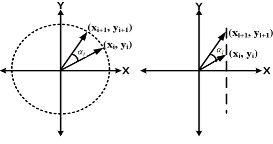
Figure 1. Graphical representation of circular and linear CORDIC
The CORDIC algorithm performs the rotation of a vector in both modes as a sequence of micro-rotations by elementary angles [4] recalled from ROM. The number of micro-rotations for a given precision is decided by radix being used for the implementation of CORDIC algorithm. The CORDIC’s graphical representation is shown in Figure 2.
Here, the circular CORDIC architecture computes trigonometric function and magnitude of a vector whereas the linear mode of CORDIC architecture computes linear functions such as multiplication and division in different mode of operation i.e rotational and vectoring mode respectively.
3.2.
Generalized CORDIC
The generalized iteration equations of the CORDIC algorithm [5] at the (i + 1)th step are as follows:
(1)
(2)
(3)
Where represents the choice of direction of rotation in each iteration, represents the radix of the number system, m steers the choice of linear (m = 0), circular (m = 1), or hyperbolic (m = -1) coordinate systems
is the nondecreasing integer shift sequence, and the rotation angle.
The latter directly depends on according to
(4)
The value of is determined by the following equation:
(5)
where z is a steering variable in rotation mode, x and y are steering variables in vectoring mode. The required micro-rotations are not perfect micro-rotations as they increase the length of the vector.
In order to maintain a constant vector length, the obtained results have to be scaled by the scale factor K as given by
(6)
(7)
3.3.
Outputs of the CORDIC algorithm
Table 1. Outputs of the CORDIC algorithm
Coordinate Rotation Vectoring
Circular (m=1)
Linear (m=0)
Hyperbolic (m= -1)
In order to better understand how CORDIC processor works, we explain the simplest form of the CORDIC algorithm with
(0, 1, 2, 3, 4 …) and
.
4.
CORDIC DESIGN
As the CORDIC is an iterative method, it requires many clock cycles to achieve the required accuracy. For a given precision, the increase of radix reduces the number of micro-rotations compared to radix-2.
Stage 1
CLK
CLK
CLK
Global-CLK
Validation Register
14 14 21
14 14 21
X0 Y0 Z0
Yn Zn
Xn
Stage 2
[image:3.595.103.233.383.557.2]Stage 14
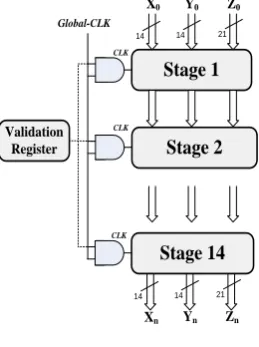
Figure 2. CORDIC schema
The CORDIC module performs 14 iterations for 14 bits precision using radix-2 number representation (Figure 3),
with the constraint that the (i+1)th iteration may begin only after the ith rotation has been completed.
4.1.
Sinus/cosines and exponential
function implementation
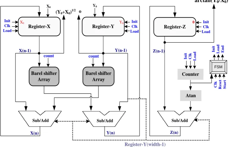
For sinus/cosines functions, we use m=1 and in the rotation mode.
If we affect to , we get cos(θ) and sin(θ) values in
Using m = -1 and
, the same algorithm can calculate exponential function (cosh(θ) and sinh(θ)) affecting . Some iteration is repeated to ensure algorithm convergence. For the implementation,
we use [14]:
(8) where z =
p an integer equal to Fix(z/ln2).
Counter Barel shifter
Array
Barel shifter Array
Sub/Add Sub/Add Sub/Add
Register-X Register-Y Register-Z
[image:4.595.120.488.88.330.2]Atan X(n-1) X(n) Y(n-1) Y(n) cosines sinus Init Clk Load Init Clk Load 0 0.60725935 count count In it C lk L o a d FSM C lk R e se t S ta r t In it L o a d E n d Z(n-1) Z(n) Init Clk Load Angle Angle Register-Z(width-1)
Figure 3. CORDIC iterative structure SIN/COS function
4.2.
Arctangent function implementation
To obtain this function, we use the vectoring mode and circular coordinates as described in Table 1.
The implementation (Figure 4) was done using the same architecture as for the first design. But, the adder/subtracter is commanded by signed numbers of register-Y.
Counter Barel shifter
Array
Barel shifter Array
Sub/Add Sub/Add Sub/Add
Register-X Register-Y Register-Z
Atan
X(n-1)
X(n)
Y(n-1)
Y(n)
(Y0+X0)1/2 o
Init Clk Load Init Clk Load Y0 X0 count
count Init Clk
L o a d FSM C lk R e se t S ta r t In it L o a d E n d Z(n-1) Z(n) Init Clk Load 0 Register-Y(width-1) Y0 X0
arctan(Y
0/X
0)
Figure 4. CORDIC iterative structure for ATAN function
5.
RESULTS OF FPGA
IMPLEMENTATION
The concept was implemented in VHDL with ModelSim SE 6.0 simulator from Mentor Graphics, verified and synthesized with Quartus II version 8.0 (32 bits) of ALTERA.
[image:4.595.106.493.415.662.2]Table 2. The synthesis results of chosen functions
Function Sinus & Cosines Arctangent Exponential
Combinational ALUT 153 /113600(<1%) 216(<1%) 178(<1%) Logic registers 61/113600(<1%) 90(<1%) 71(<1%)
Pins 53/733(7%) 76(9%) 68(9%)
Latency 78 ns 108 ns 168 ns
Max frequency is 250 Mhz and we obtain 1% area occupation of FPGA. Latency is different for such function because it’s not the same mode and not the same number of iteration. It depends on the clock frequency.
6.
PRECISION WITH CORDIC
METHOD AND ERROR ANALYSIS
In this section, we will conduct simulations to show the effectiveness of the proposed architecture. To analyze the error performance, we define the error as the distance between the ideal rotated point and the feasible rotated point divided by the ideal rotated point. The error is thus determined by:
(9)
In the design flow, one important step is the fixed-point simulation on which we assist to determine the required word-length. If the word-length is over-determined, we will suffer from higher cost and slower computational speed.
So, we will explore the 14-point format for the data and we will fix the scaling factors. The following relative error curves present the CORDIC precision after the extraction of the values from ModelSim simulation, which are generated from the test bench
.
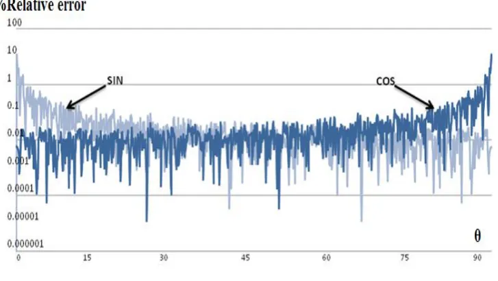
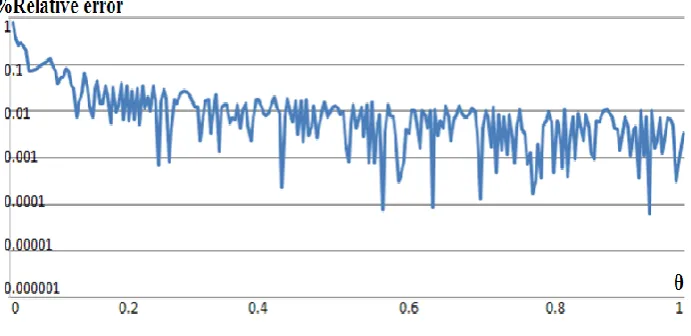
Figure 5. Relative error of CORDIC sinus/cosines functions
For , the error for sinus /cosines ranges within 0.001 % to 1 % and the mean relative error is 0.013 %.
We notice that we have peaks in where K is an integer.
[image:5.595.122.482.597.743.2]Affecting the scale factor in the input ( ) and zero in the input ( ) and using the rotation mode, we can calculate the cosh and sinh functions with hyperbolic coordinate. We can get the exponential value:
= cosh(x) + sinh(x) (10)
[image:6.595.126.472.128.296.2]The mean error for exponential is about 0.005 %, an acceptable error in the specified convergence range.
Figure 7. Relative error of CORDIC arctangent function
For the arctangent function, the mean error does not exceed 0.01%.
7.
CONCLUSION
This paper proposes CORDIC architecture as an approach to implement some operators in a fingerprint recognification application. The CORDIC architecture leads to fast and small operators up to 14 bits of precision.
The principal drawbacks of this algorithm are the requirement of a scale factor and the slow rate of convergence. The convergence range can be extended over the entire coordinate space by repeating certain iteration steps and by exploiting the symmetry of the coordinate axes. To cover the whole coordinate space, we compute the angle on the interval [0, 90°]. The result of CORDIC rotations for any angle between 90° and 360° can be extrapolated for the result of a rotation corresponding to [0, 90°].Our basic CORDIC processor has been designed in VHDL implementation. The implemented architecture is dedicated to the computation of trigonometric, exponential and arctangent functions with internal wordlength of 14 bits. Nevertheless, it can be adapted to all functions by reprogramming the FPGA.
The module uses radix-2 number representation, this leads to small circuits by replacing the costly multiplications by a small number of additions. The obtained operators provide very small average error with reasonable maximum error what’s makes our algorithm suitable for many applications.
8. REFERENCES
[1] Ray and Andraka, “ A Survey of CORDIC Algorithms for FPGA based Computers”, Andraka Consulting Group, Inc, North Kingstown, RI02852, 2011.
[2] Gualberto Aguilar, Gabriel Sánchez, Karina Toscano, Mariko Nakano-Miyatake, Héctor Pérez-Meana. “Automatic Fingerprint Recognition System Using Fast Fourier Transform and Gabor Filters”, Cient’fica Vol. 12 Nœm. 1 pp. 9-16, ESIME-IPN. ISSN 1665-0654 , 2008
[3] P.K. Meher, J. Valls, T.B. Juan, K. Sridharan and K. Maharatna, “50 Years of CORDIC: Algorithms, Architectures, and Applications”, IEEE
TRANSACTIONS ON CIRCUITS AND SYSTEMS—I: REGULAR PAPERS, vol. 56, no. 10, pp. 9, Sept. 2009
[4] J. E. Volder, “The CORDIC trigonometric computing technique”, IRE Trans. Electronic Computers, vol. 8, no. 3, pp. 330{334, Sept. 1959
[5] J. S. Walther, “A unified algorithm for elementary functions”, Proc. AFIPS spring Joint Comput. Conf., pp. 379{385, 1971
[6] M. D. Ercegovac, and T. Lang, “Redundant and On-Line CORDIC: Application to Matrix Triangularization and SVD”, IEEE Trans. Comput., vol. 39, no. 6, pp. 725{740, June 1990
[7] N. Takagi, T. Asada, and S. Yajima, “Redundant CORDIC methods with a constant scale factor for sine and cosine computation”, IEEE Trans. Comput., vol. 40, no. 9, pp. 989-995,Sept., 1991
[8] J. Duprat, and J. M. Muller, “The CORDIC algorithm: new results for fast VLSI implementation”, IEEE Trans. Comput.vol. 42, no. 2, pp. 168-178, Feb. 1993
[9] D. Timmermann, H. Hahn, and B. J. Hosticka, “Low latency time CORDIC algorithms”, IEEE Trans. Comput. vol. 41, no.8, pp. 1010-1015, Aug. 1992
[10] H. Dawid, and H. Meyr, “The differential CORDIC algorithm:constant scale factor redundant implementation without correcting iterations”, IEEE Trans. Comput. vol. 45, no. 3, pp.307-318, Mar. 1996
[11] Pongyupinpanich Surapong, Faizal Arya Samman and Manfred Glesner, “Design and Analysis of Extension-Rotation CORDIC Algorithms based on Non-Redundant Method”, International Journal of Signal Processing, Image Processing and Pattern Recognition Vol. 5, No. 1, March, 2012
[13] Stefan Lachowicz and Hans-Jorg Pfleiderer, “Fast evaluation of the square root and other nonlinear functions in FPGA”, 4th IEEE international symposium on electronic design, 2008
[14] Anis BOUDABOUS, Fahmi GHOZZI, M. Wajdi KHARRAT, Nouri MASMOUDI, “Function Generator
![The quality of ‘egusi’ melon [(Citrullus lanatus Thunb.) Matsum and Nakai] seeds derived from fruits harvested at different growth stages and at different positions on the mother plant](data:image/gif;base64,R0lGODlhAQABAIAAAP///wAAACH5BAEAAAAALAAAAAABAAEAAAICRAEAOw==)