Defensive Mechanisms of Selective Forward Attack in
Wireless Sensor Networks
S. Sharmila
Research Scholar, Anna University
Coimbatore, India
G. Umamaheswari
Associate Professor,
Department of Electronics and Communication Engineering,
PSG College of Technology
ABSTRACT
Wireless sensor networks are composed of a large number of sensors and their major challenge is energy consumption in order to prolong the life time of the network. From the security point of view, detecting schemes must be very light to increase the life time of the network. In this paper, defensive mechanisms based on cumulative acknowledgement and energy based is proposed to detect selective forward attack in mobile wireless sensor networks. The proposed mechanism is simulated with Berkeley Mica 2 Motes configuration in Network Simulator Version 2 and Glomosim. The scheme is evaluated in terms of packet delivery ratio and throughput.
Keywords
Wireless Sensor Network, Routing Attack, Selective Forward Attack, Acknowledgement based, Energy Based, Wireless Sensor
1. INTRODUCTION
Wireless sensor networks are vulnerable to many routing attacks such as Selective forward attack , HELLO flood attack , sinkhole attack, Wormhole attack ,etc because of broadcast nature of transmission medium, resource limitation on sensor nodes and uncontrolled environments where they are left unattended. The existing security mechanisms are inadequate and new approaches are required for each routing attack since each attack has its own nature and characteristics. The major aim of this work is to detect the selective forward attack which also meets the security goals such as data authenticity, integrity, and availability [1-4].
The security objectives are as follows:
1. To design defensive mechanisms against selective forward attack considering the resource constraints of mobile nodes.
2. To identify the malicious node on forward routing path.
3. To provide data authenticity and data integrity. 4. To improve the detection accuracy and data
availability.
2. SELECTIVE FORWARD ATTACK
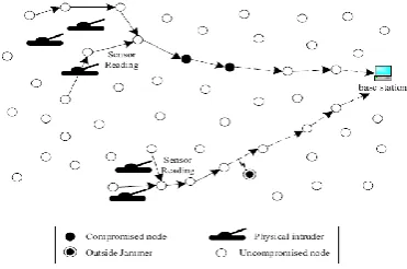
Selective forwarding attacks may corrupt some mission critical applications. In these attacks, malicious nodes behave like normal nodes in most time but selectively drop sensitive packets, such as a packet reporting the movement of the opposing forces. Such selective dropping is hard to detect. Counter measures to selective forwarding attacks cannot identify malicious nodes or require time synchronization. [image:1.595.336.522.291.414.2]However, if a malicious node is present on a route through which packets are forwarded, attackers can deliver selective forwarding attacks by simply dropping packets.
Figure 2 An Example sensor network under Selective Forward Attack
Selective forwarding attacks can cause serious threats on many applications. Figure 2, shows that the Selective forwarding attacks has some m nodes which drop some or all packets. Attacker can launch the selective forwarding attack and drop a portion of packets for which it need store lay while forward the rest. Selective forwarding attack is hard to detect, since packet drops in sensor networks may be caused by unreliable wireless communications or node failures [6].
3. DEFENSIVE MECHANISMS
This Section describes the defensive mechanisms of selective forward attack in Mobile Wireless Sensor Networks. The Mechanisms are based on Acknowledgment based and energy based.
3.1
Acknowledgement Based
The different phases of the proposed mechanism are as follows: 3.1.1. Node id assignment phase and location Phase
3.1.2. Topology identification 3.1.3. Forward route selection path 3.1.4. Check Point assignment 3.1.5. Data transmission 3.1.6. Malicious node detection
3.1.1
Node id and Location Phase.
Node id is activated only when the transmission is required. Node id is configured dynamically per session by the sink node/base station. Whenever the sink node/base station needs any information it broadcasts the set of node ids and activates the timer. Node id is valid until timer expires. Base station stores the allotted node id temporarily for each session temporarily.
3.1.2
Topology identification phase
After receiving the node id, the node identifies its neighbor node and stores the next hop neighbor id to dentify the topology of the network.
3.1.3
Forward route selection path
The source node sends the route_ request packet to the destination node/base station. It responds the route_reply packet with the selected forward path through which data is transmitted. Forward path is selected based on the Dynamic source routing protocol.
3.1.4
Check point selection phase
Base station/Destination node assigns the nodes to be the check point in the forward path randomly. In the downstream link, check point generates a trap message after the successful reception of the packet.
3.1.5
Data transmission phase
Once the forward path is selected, data is transmitted from the source to the base station/destination node. Upon successful reception of data, each node sends an acknowledgement packet to its next node which lies in the forward path. The acknowledgement packet of next node and previous node is forwarded to next neighbor node in the forward path. In this way, acknowledgement packets are cumulated. Once the check point receives the cumulative acknowledgement packet, it generates the trap message and sends to its next node in the forward path. If the destination receives the trap message generated by the last check point, it shows that the data has been successfully transmitted from the source and the destination.
3.1.6
Detection process
Step: 1 Base station issues the node id and it is dynamic and unique for a window.
Step 2: Base station sends the data request to all the nodes. Step 3: Source nodes send a route request packet to the base station.
Step 4 : Base station sends a route reply packet to the source station .
Step 5: Base station selects the node in the forward path as check points.
Step 6. : Source node sends the data packet to the next node which lies in the forward path. Upon receiving the data the node sends the acknowledgement packet and the receiving node sends its acknowledgement packet along with the data packet and thus frames the cumulative acknowledgement.
Step 7: Once the check point receives the cumulative acknowledgement, it generates the trap message and it is forwarded along with the data to the next check point.
Step 8: Upon receiving the cumulative acknowledgement packet and the trap message, the base station detects the exact malicious node in the forward path based on the negative
acknowledgement. If any node holds its id after a predetermined time interval of the window that node is also suspected as a malicious node and is illustrated in Algorithm.
Step 9: Once the malicious node is detected it is removed from the network and the packet is forwarded through the alternate path.
Window-A 30
2
31
14 13
41
9 21
22 28
15
7
10 35
16 20
39 6
12 32
1
36 37
38 5
8
40 17
25
4
26 18
33
23
19
11
3
24
27 34
B S 50
49
42 46
47
43 45
48
44 Algorithm: Determining malicious node
Input:
CAKP : A cumulative packet received {Datan,ACKo,ACK1,…….ACKn}
Trap :{check point id, rds, node id of NACK} n: Total # of ACKs in CAKP
m: Total # of nodes in the forwarding path 1. create a list of responses [] and
traps[] of length m 2. for i=0,….n-1
responses [n-1]<- ack n-i
remove ack n-i from CAKP
if ack n-I == n then
return {rds=1 } else {rds=0} retrun ckpid endif
3. for i=0,……., n-1 traps [n-i] <- nids(nack) remove and ckpid and rdsfrom trap[]
4. for i=0,……., n-1
if ckpidi [trap] != ckpidi+1 then if (rdstrap[]==1) then return ckpids else
return the nids(nack) end if
Window B
Figure. 3.1 Node-id Detection
4. A DETECTION ANALYSIS
The proposed detection mechanism has been analyzed based on following background:
Scenario 1: Based on node id
If any node holds the id after the timer expires, that node is suspected to be a malicious node. The value of the timer depends on the number of hops in the forward routing path and maximum transmission delay. Packet delivery ratio, throughput are further analyzed to confirm the node to be a compromised node. In Figure 3.1, the node id’s of Window A and Window B are different except the node ids such as 45,15 and 21 and such nodes are treated as malicious nodes.
[image:3.595.325.518.187.348.2]Scenario 2: Check-point detection
Figure. 4.1 Check-point detection
The Check-points are randomly selected, if the base station/destination selects the malicious node as check-points that generate acknowledgement and trap message on its own and forward the packet to its neighbor node. In that case, detection of malicious node may be suspected based on the node id and packet delivery ratio. Check point id is valid until window expires. In Figure 3.2 Node 26 and 67 are source nodes whereas BS is the base station and it is treated as destination node and forward paths are 26-54-22-6-52-36 and 67-13-44-78-21-88-17-62 respectively. Check points are 22, 16 and 21.The forward path from the source 26 to base station does not contain any malicious node. But the forward path from 67 to the Base station contains 21 as check point but it is also a malicious node. In this case, check point is a malicious node and it is detected based on node id and packet drop ratio.
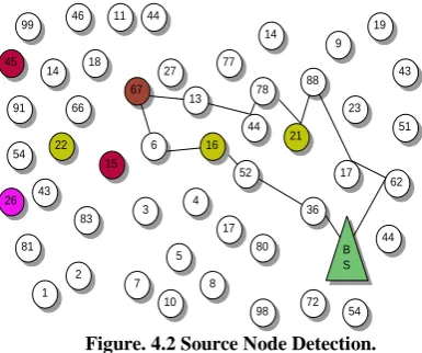
Scenario 3: Source node detection
The base station broadcasts the request to nodes, and the malicious node responds to the base station with route_request packet station to gather the routing information and misguide the route in the network. Figure. 3.3 shows that malicious node 67 voluntarily responds to the base station after receiving the route_request and misguides the route. The actual forward path is 67-6-16-52-3 instead of 67-13-44-78-21-88-17-62. The node is detected based on the packet drop ratio and based on cumulative acknowledgement packet.
Figure. 4.2 Source Node Detection.
[image:3.595.67.268.411.575.2]Scenario 4: Node can be a compromised node
The existing methods such as CHEMAS, CADE, [2][3][4][5] detect any two nodes in the selective forward path as malicious node . In CHEMAS, authors suggest that malicious node lies within the range of check points. In CADE, authors present the detection mechanism to identify the two malicious nodes in the forward path. The proposed mechanism detects the exact compromised nodes. Check point generates a trap message and forwards it to the next check point stating that there is no packet drop exists up to that check point. Between the two check points, acknowledgements of each node are cumulated if the data has been transmitted successfully. Once the check point receives the cumulative acknowledgement successfully then it generates the trap message. If any node between the check points fails to forward the data packet, Cumulative acknowledgment and trap message, that node is suspected to be compromised node. Cumulative Acknowledgment packet can also drop by collision and timer expiry since nodes are mobile nodes. Overlap of window causes the packet drop in the network. Check point should not misjudge an ordinary node to be a compromised node. In Figure 3.4 Node 4 drops the cumulative acknowledgement packet and it is treated as compromised node. Based on the Negative acknowledgement, the compromised node is identified.Figure. 4.3 Node as Compromised Node
99 46 14 45 18 66 11 26 44 91 27 6 13 3 83 43 7 1 81 26 54 22 2 4 77 52 44 78 14 88 21 36 80 8 10 5 98 17 72 48 17 23 9 19 43 5 62 44 54 B S 15 99 46 14 45 18 66 11 67 44 91 27 6 13 3 83 43 7 1 81 26 54 22 2 4 77 52 44 14 88 21 36 80 8 10 5 98 17 72 17 23 9 19 43 51 62 44 54 B S 15 16 78 99 46 14 45 18 66 11 67 44 91 27 6 13 3 83 43 7 1 81 26 54 22 2 4 77 52 44 14 88 36 80 8 10 5 98 17 72 17 23 9 19 43 51 62 44 54 B S 15 16 78 21 Source Destina tion
[image:3.595.323.548.642.688.2]Format of the Cumulative Acknowledgement packet
Da ta
Ack 0
Ac k1
… Ack N
NACK
Format of the Trap message
Check point Node id
RDS Node ids of NACK
If NACK is set to 0, it denotes that it is a negative acknowledgement of data packet and if it is set to 1, it denotes that it is a negative acknowledgement of route, if the node has not seen the route packet sent by the base station/destination. Received data successfully (RDS=1) denotes that data is received up to the particular check point indicated by its node id. Once the destination/base station identifies the malicious nodes, the destination broadcasts the node id of NACK packet .Source requests the destination to send the alternate forward path.
4.1
Energy Based
The proposed detection scheme is the first detection scheme that identifies the malicious node based on the energy value of the node. The network is divided into virtual grids in order to reduce the energy consumption. The forwarding path is identified by dynamic source routing protocol. This scheme also detects more than one malicious node in the network[10-14].
5.
DETECTION SCHEME
The following are the different phases of the proposed mechanism:
1. Grid Formation and Grid Head assignment 2. Energy allocation
3. Forward route selection path 4. Data transmission
5. Detection of malicious node
5.1 Grid Formation and Grid Head assignment
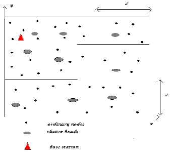
[image:4.595.343.513.71.226.2]At first with the specific terrain range, sensor nodes are divided in to virtual girds. Since nodes are scattered and also mobile. Control packets are required to identify the adjacent nodes and to identify the forward routing path. Nodes which are located far away from the base station consumes large amount of energy. Communication consumes a large amount of energy and thus reducing the node life time .In order to increase the node life time we first framed the virtual grids. The total terrain range which is in square of size d X d is equal divided in order to form the grids. The grid is identified with the help of x and y coordinates. The node which is having the highest energy is assigned as the grid head which is required to co-ordinate with other nodes in order to find out the destination. Base station randomly assigns the nodes to be the grid head in each grid based on the highest energy value Grid head is necessary to prorogate the information data packets to its neighbor nodes. Grid head takes responsibility for routing the packets and to improve the quality of the routes the grid head be the node with the largest residual energy in each grid and is randomly assigned.
Figure 5.1 grid formation
The network is divided into logical grids. Grids are formed based on the x and y coordinates assigned Figure 3.5 represents that, the base station is located at the first grid. It is stationary, but all the other nodes and grid head are mobile nodes. The size of each grid is 159m. The terrain of first grid starts from (0, 0) and ends with (159,159). For 500 nodes there are 63 grids. Each grid consists of grid head per Equation -1 is used to identify the node is located in which grid.
5.2 Grid Head assignment
The node which is having the highest energy is selected as Grid head. If the same nodes are acting as grid head for a long time, then the life time of the nodes is reduced. We used a random algorithm for selecting the grid head .i, e grid head is randomly assigned and it is changed frequently. The selection factors of the grid are information that can be transferred from the nodes and to the base station, communication cost, detects the malicious node in the forward routing path, power of the node. If the grid head is located near by the base station and with the adjacent grid head then the communication cost is reduced. The problem is how to formulate the criteria to select the grid head in order to select the nodes that provides satisfied data from source node to the base station.
When node i is selected frequently, the energy of the node decreases because grid head will act as gateway of the grid and can lead to the degradation of the performance of the network. Since the nodes are mobile, the coefficients mentioned in the equation -2 are adaptive and it should be flexible with respective to Grid size, noise model, receiver sensitivity and movement of sensors.
5.3
Energy allocation
Initially, Energy is allocated to all the nodes in the network by the base station. k is the energy value of each node. During energy distribution k value is equal to 100 units. This energy can be consumed 20 units for transmission, 20 units for reception, 20 units for computing grid formation, route selection path and checking the node energy. The 30 units for packet drop and collision, and 10 units for connection establishment. In the 30 units of packet drop and collision, 10 units are consumed for collision and the remaining 20 units are considered as essential. If the value of k in collision and packet drop is less than the ESS then it is suspected as a malicious node Where ESS is essential energy and is assumed to be 20. These values are assigned for the simulation purpose and it is subject to change practically with respect to grid size, noise model, receiver sensitivity, and movement of sensors.
5.4
Forward route selection path
Each grid head first identifies the source node is located in that particular grid. Then the grid head sends the request to the adjacent grid head. After the identification of source node, it sends the route_ request packet to the destination node/base station. It responds route reply packet with the selected forward routing path through which data is transmitted.
[image:5.595.309.523.73.343.2]5.5
Data transmission
Figure 3.6 Data transmission
Figure 3.6 depicts the transmission of data between the grids. First the data is transmitted from the base station to the grid head of the virtual grid, and then the grid head checks for the node which needs to transmit the data from the base station. If the source is not located in that specific grid, then the request is transmitted to the next grid head will continue the process of checking the nodes in that grid and then transforms it to the particular node. In figure Base Station is represented by the triangle symbol, grid head is represented by ash color circle; ordinary nodes are represented by a black color circle. Data packet to be transmitted is represented using a colored circle. Transmission of packets from base station to the node is represented by the arrow heads clearly.
The data transmission phase is summarized as follows: 1. Base station sends request to the grid heads in the
corresponding grids.
2. The grid heads delivers the request to all the nodes located in that grid for identifying the source. If the source is not located in the grid then the request is transferred to the next grid.
3. After the identification of the source, it sends the route request packet to the base station. Then the base station reply the route selection path in order to transmit the data
4. Route identification and data transmission is done by using the control packets in the dynamic source routing protocol
5. The nodes sends an acknowledgement to the grid head
6. The grid head sends the acknowledgement to the base station.
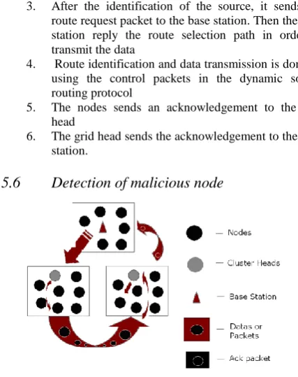
[image:5.595.58.286.348.507.2]5.6
Detection of malicious node
Figure 3.7 Detection of Malicious node
The detection phase of Figure 3.7 is mainly based on the acknowledgement packets from the grid head to the base station and the energy level of each node. If the base station gets the proper acknowledgement for each transmission means there might be no malicious nodes in the transmission path. If the base station fails to get the acknowledgement packet within the time period means it will check the energy level of each nodes in the grid using grid head. The node which is having energy level lower than its essential and drops its acknowledgment packets is detected as the malicious node by the base station and after detecting the malicious node it is removed from the network in order to maintain the proper transmission of data .packet is forwarded to destination or base station by choosing the next alternate path. Pack drop may occur due to lack of receiver sensitivity and collision since nodes are mobile nodes. In that there is chance for identification of normal node as malicious node.
6.
DETECTION ANALYSES
The proposed detection mechanism has been analyzed based on following scenarios:
Scenario 1: Grid head detection
The Grid heads are mobile and randomly selected; it will search whether the nodes of forwarding path lie in the specific grid or in the adjacent grid. Since only 30 units of energy is allocated for the packet delivery and collision. There is a chance of assuming the malicious node as grid head based on the initial energy. In that case grid head is identified as malicious node if it drops any route acknowledgement packet further confirmation is done by considering it collision rate and packet delivery ratio.
Scenario 2: Source node detection
misguide the route in the network. In this case malicious node is identified by the Grid head based on energy level allotted for packet delivery and collision.
Scenario 3: node may be malicious node
Any node which lies in the forward path may be malicious node and grid head checks for the energy level of each node. If the energy level is less than the essential energy and by, after considering its drop ratio the node is suspected as malicious node.
6.1
Performance Evaluation
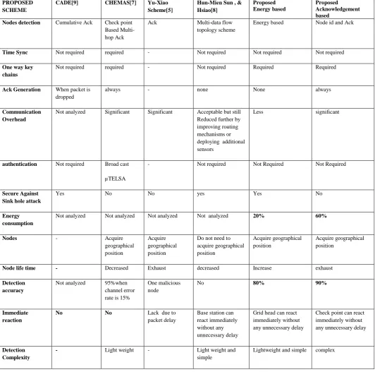
The Comparison of our scheme with the previous schemes is given in table-3.1. CADE does not need the authentication since it sends acknowledgements to the base station in a cumulative manner but it needs data reply packet. When compared with CHEMAS, overhead is minimized because acknowledgement is generated only when packet drops occur in the network. Yu-Xiao Scheme also detects the malicious node in the forwarding path based on acknowledgement but main drawback of the schemes is lack of efficiency, security, scalability, and immediate reaction. Hun-mien sun and hsiao proposed lightweight and simple scheme for defending against the selective forward attack. To the best of our knowledge, energy base detection scheme is the first scheme that identifies malicious nodes.
7.
CONCLUSION
The malicious node is detected based on the acknowledgement and energy level of the node. The energy consumption of the detection scheme is less when compared with existing detection schemes. From the simulations, byte overhead is 0.39 percentages and detection accuracy is 80% are observed and thus increasing the network throughput. These results show that the packets can be forwarded without any selective packet drop by minimizing the malicious nodes in the network. The further enhancement of the proposed scheme is to improve the success rate to 100% with various mobility and receiver sensitivity of the node.
8.
REFERENCES
[1] A.Perrig,R.Szewczyk, V.Wen, D.culler and J.D.Tygar, “SPINS: Security protocols for Sensor Networks”, ACM Journal of Wireless Networks, pp 521-5234, September 2002.
[2] W.Lee and Y.Huang, “Intrusion Detection Techniques for Mobile Networks,” ACM wireless networks journal, September 2003.
[3] C. Karlof and D. Wagner, “Secure Routing in Wireless Sensor Networks: Attacks and Countermeasures”, Ad Hoc Networks, 1(2-3):293–315, 2003.
[4] Swades De, Chunming Qiao , Hongyi Wu, “Meshed multipath routing with selective forwarding : an efficient
strategy in Wireless sensor networks , Computer Networks”, The International Journal of Computer and Telecommunications Networking, Vol 43, Issue 4, pp. 481-497, November 2003.
[5] B. Yu and B. Xiao, “Detecting Selective Forwarding Attacks in Wireless Sensor Networks”, in the Proceedings of. 20th International Sympsium on Parallel and Distributed Processing (IPDPS 2006), pp.1-8, 2006. [6] C.E.Loo, M.Y.Ng, C.Leckie and M Palaniswami,
“Intrusion Detection for routing attacks in sensor networks”, International Journal of distributed sensor networks”,Vol.2, pp, 313-332, 2006.
[7] B. Xiao, B. Yu, and C. Gao, “CHEMAS: Identify Suspect Nodes in Selective Forwarding Attacks”, Journal of Parallel and Distributed Computing, Vol. 67, Issue 11, pp. 1218-1230, 2007.
[8] Hung-Min sun, Chien-Ming chen and Ying-Chu Hsiao, “An Efficient countermeasure to the selective forwarding attack in wireless sensor networks”,1-4244-1272-2/07/$25.002007 IEEE.
[9] Young Ki Kim, Hwaseong Lee, Kwantae Cho, and Dong Hoon Lee, “CADE:Cumulative Acknowledgement Based Detection of Selective Forwarding Attacks in Wireless Sensor Networks”, in the Proceedings of third International Conference on Convergence and Hybrid Information Technology, 2008.
[10]Nguyen Xuan Quy and Dugki Min , Eunmi Choi, “An Energy-Efficient Data Dissemination protocol for Grid-Based Wireless Sensor Networks”, IEEE International Conference on Research, Innovation and Vision for the Future in Computing Communication Technologies, RIVF 2008, Ho Chi Minh City, Vietnam, 13-17 July 2008. [11]Jeremy brown and Xiaojiang Du, “Detection of Selective
Forward Attacks in Heterogeneous Sensor Networks”, published in the Proceedings of ICC 2008.
[12]Tran Hoang Hai and Eui nam Huh, “Detecting selective forwarding attacks in wireless sensor networks using two-hops neighbor knowledge”, in NCA, pages 325–331, 2008. [13]Jing wu,lijia len,pu-lia yan,” New Reliable Routing Method Based on Probabilistic Forwarding in Wireless Sensor Network 2009.
Table 3.1 Performance Analysis
PROPOSED SCHEME
CADE[9] CHEMAS[7] Yu-Xiao
Scheme[5]
Hun-Mien Sun , & Hsiao[8]
Proposed Energy based
Proposed Acknowledgement based
Nodes detection Cumulative Ack Check point
Based Multi-hop Ack
Ack Multi-data flow
topology scheme
Energy based Node id and Ack
Time Sync Not required required - Not required Not required Not required
One way key chains
Not required required - Not required Required Required
Ack Generation When packet is dropped
always - none None always
Communication Overhead
Not analyzed Significant Significant Acceptable but still Reduced further by improving routing mechanisms or deploying additional sensors
Less significant
authentication Not required Broad cast
µTELSA
- Not required Not Required Not Required
Secure Against Sink hole attack
Yes No No yes Yes No
Energy consumption
Not analyzed Not analyzed Not analyzed Not analyzed 20% 60%
Nodes - Acquire
geographical position
Acquire geographical position
Do not need to acquire geographical position
Acquire geographical position
Acquire geographical position
Node life time - Decreased Exhaust decreased Increase exhaust
Detection accuracy
Not analyzed 95%when channel error rate is 15%
One malicious node
No 80% 90%
Immediate reaction
No No Lack due to
packet delay
Base station can react immediately without any unnecessary delay
Grid head can react immediately without any unnecessary delay
Check point can react immediately without any unnecessary delay
Detection Complexity
- Light weight - Light weight and
simple