A New Control Method for Series Active Filter in
Distribution System using Unit Vector Control
T.Guna Sekar
Assistant Professor Kongu Engineering College
Erode-638052, India
R. Anita,
PhD. Professor & Head Department of EEEIRTT, Erode-638 316
R.Chandrasekar
M.E. (Applied Electronics) Kongu Engineering College
Erode-638052, India
ABSTRACT
The Novel control strategy for reduction of harmonics in three-phase four-wire distribution systems was presented in this paper. The single phase loads connected to 3P4W distribution system causes an unbalance current which results in the flow of zero sequence harmonic component in the neutral conductor of the distribution system. This effect leads to over-burden on neutral conductor and also de-rates the distribution transformer. A Unit Vector Control (UVC) based series active filter was proposed to reduce the harmonic currents in the neutral conductor during both balanced and unbalanced loading conditions. In this method a series active filter is placed in series with the neutral conductor. The proposed method reduces the harmonics, improves the power factor and balances the asymmetrical loads. The detailed analysis of the proposed method based on unit vector control was presented. The simulation results based on MATLAB/SIMULINK were performed to verify the effectiveness of the proposed method. The results are found to be quite satisfactory in mitigating harmonics in the neutral current.
Keywords
Power Quality, Total Harmonic Distortion (THD), Active Power Filters, Neutral Conductor
1.
INTRODUCTION
Contamination of the power supply due to harmonics is a very harmful and serious problem in Electric Power System. With increase in the advancement of information technology, the large number of computers and power electronic devices are connected to the distribution systems. Electric power is distributed through a three-phase, four-wire system in many industrial and commercial sectors. Most of the loads in the distribution system are connected to any one of the phase of three-phase four- wire distribution system, which leads to the unbalanced loading conditions. Due to this, a zero sequence harmonic current and unbalance current flows through the neutral conductor [1]. The power supplies consists of rectifier with DC smoothening capacitors may also leads to excessive current harmonics in the neutral [2].
These excessive harmonic currents causes the problems viz; over loading of the neutral conductor, increases the size of the neutral conductor, de-rating of the distribution transformer and overheating of the distribution transformer.
Survey results across computer sites in U.S. shows that 22.6% of the sites have neutral currents exceeding the full-load phase currents [3]. Almost 95% of the harmonic current in the neutral are zero sequence component (3rd order harmonics).In
order to overcome this, various techniques like passive filters, Zigzag transformer connections, active filter techniques were proposed. In order to attenuate these harmonic current in the distribution system, traditionally a passive filter was designed [4] [5] which was connected across the non-linear load. But this compensation leads to some of the drawbacks [6] like occurrence of series and parallel resonance which causes an incomplete potential.
Also an effectiveness of the passive filter depends on the network impedance as well. [7] Proposed a zig-zag connection of transformer for harmonic suppression in the neutral conductor. This scheme can able to attenuate harmonics but leads to system complexity and increases the losses due to transformer windings.
Due to advancement in the technology, active power filters have become most habitual compensation methods. Shunt active power filters for three-phase three-wire and three-phase four-wire distribution systems have been presented [8] – [12]. This filter was widely used in transmission systems but has fewer effects on the distribution systems. In [13], author itself mentioned that shunt active filter compensation was not perfect solution. Improved solution to harmonic problem uses a hybrid active filter, which consists of shunt active and passive filter or series active and passive filters [14] – [16]. Recently, in order to improve the power quality and to correct the unbalance voltage in the distribution system, a series active power filter is connected in series with the neutral conductor were proposed [17] – [19]. The above mentioned methods used various controllers like Instantaneous reactive power theory [20], Synchronous Reference Frame theory [21] and Sliding Mode control theory [19]. All these theories were able to extract and mitigate the harmonics present in the neutral only under the balanced load conditions.
In this paper, a novel control strategy based on Unit Vector Control is presented. The proposed method uses only an active power filter in series with the neutral conductor. It performs several functions simultaneously viz; current harmonics, load unbalance and neutral current cancellation. The rating of the proposed series active filter is less than 10% of the harmonic producing loads. The simulation results for parallel RC load with rectifier circuit are shown for both balanced and unbalanced conditions.
2. PROPOSED SYSTEM
CONFIGURATION
The block diagram of the proposed method for three-phase four-wire distribution system is shown in Fig 1 and
[image:2.595.60.275.151.284.2]the proposed system configuration is shown in Fig
[image:2.595.328.540.190.361.2]Fig 1. Block diagram of the proposed method
Fig 2. System configuration of the proposed method
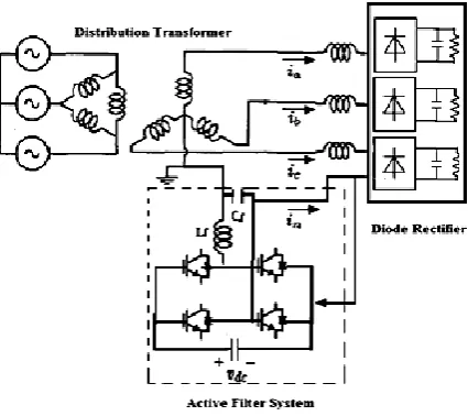
In the block diagram, Ia, Ib, Ic and In represents a phase currents and the neutral current respectively. The neutral current is sensed and given to the controller. The controller generates the pulse equivalent to the harmonic currents which is given as triggering to the inverter. The inverted injects the harmonic current to the neutral there by harmonics in the neutral conductor gets suppressed.
The series active filter is placed in the neutral conductor of the three phase four wire distribution system. It consists of 2-leg IGBT based inverter and a DC charging capacitor. The series active filter is connected to the neutral conductor through the linking capacitor (Cf) and inductor (Lf). In the distribution system, the single phase loads are connected between any one of the three lines and a neutral as shown in Fig 2. The each phase of three phases is connected to a rectifier with RC load. The active filter system consists of a two-leg inverter circuit with DC charging capacitor.
3. UNIT VECTOR CONTROLLER FOR
SERIES ACTIVE FILTER
The controller based on Unit Vector Control is shown in Fig 3. Due to various single phase loads connected to three-phase four-wire distribution system, the unbalance current flows through the neutral conductor. This neutral current (In) contains both fundamental component (Inf) and the harmonic component (Inh).
Fig 3 Controller for Series active Filter
The fundamental component is due to the unbalanced loading and the harmonic component is due to the non-linear loads in the system. The neutral current is multiplied by both cos function (cosᾠt) and sin function (sinᾠt) to extract the fundamental components from the neutral current. Then the component is passed through the low pass filter which extracts the DC component. The extracted DC component is converted in to ac component by multiplying again with cosᾠt and sinᾠt respectively.
Then the ac component of neutral current fundamental (Inf) is extracted and multiplied with the constant for normalization. This component is subtracted with the neutral current In, to obtain the harmonic component (Inh) of the neutral current. Then the component is multiplied with the inverter gain (Kh) to get the voltage signal (Vinv) and compared to the triangular carrier to generate the PWM gating pulse through relational operator.
Vinv=KhIn
In = -(VLa+VLb+VLc)/ (Zs+ZL+3Zn+3Kh),
Kh is the gain of the series active filter inverter. The gating pulse is applied to the series active filter inverter circuit to inject the corresponding harmonic component in the neutral conductor. Thus the injected harmonic current and the neutral harmonic current gets cancelled there by over burden on neutral conductor can be reduced.
4. SIMULATION RESULTS
[image:2.595.57.270.320.509.2]MATLAB/SIMULINK. The following are the system parameters used for the simulations. VLN = 120V (Line to neutral voltage), Leakage reactance of the distribution transformer = 0.35mH, Output filter Lf = 0.2mH and Cf = 1µF, and System frequency = 50Hz. The simulations are carried out under two conditions; a) balanced loading b) unbalanced loading.
4.1 Balanced condition
[image:3.595.320.536.72.381.2]The proposed controller is simulated under balanced loading conditions. The load values are given as Ra, Rb, Rc = 25Ω and Ca, Cb, Cc = 1500µF. Fig 7 shows the simulation results for phase a, b, c and neutral current without series active filter.
Fig 5 Waveform of phase and neutral currents without filter
(a)
(b)
(c)
[image:3.595.55.280.253.390.2](d)
Fig 8 FFT analysis of phase currents (a, b and c) and neutral current (d) before active filter compensation
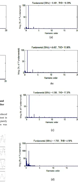
[image:3.595.320.539.605.750.2]The simulation result shows that harmonic content flows through the neutral and phase conductors. The waveform of the phase currents are distorted and the neutral current also carries large amount of current due to non-linear loads. The FFT analysis of the phase and neutral currents without filter are shown in fig 8. It shows that the triplen harmonics especially 3rd order harmonics are more predominant in the phases and the neutral conductors. The magnitude of 3rd harmonic in the neutral is very high before the compensation of series active filter. The simulation results for phase a, b, c and neutral current after compensation of series active filter is shown in fig 9. The wave form of the neutral is nearly sinusoidal and its magnitude also reduced to large extent. Due to the effect of placing series active filter in the neutral conductor, the harmonic component present in the phase conductor also reduced and the waveform becomes nearly sinusoidal.
(a)
(b)
(c)
[image:4.595.55.278.45.668.2](d)
Fig 10 FFT analysis of phase currents (a, b and c) and neutral current (d) after active filter compensation
Simulation Results under Unbalanced
condition
The proposed controller was simulated under unbalanced loading conditions. The load values were given as
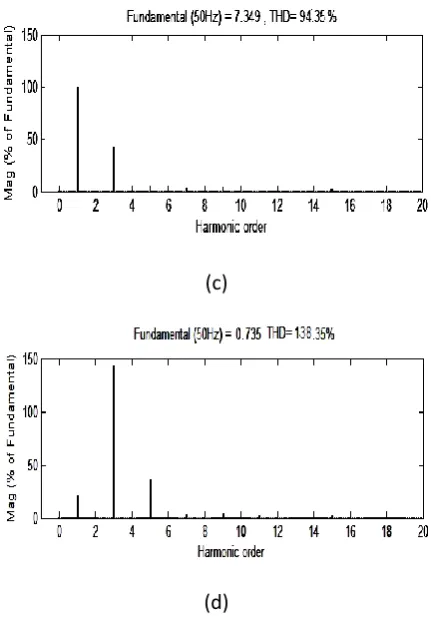
[image:4.595.318.538.247.410.2]Ra = 15Ω, Rb = 25Ω, Rc = 50Ω and Ca, Cb, Cc = 1000µF with the diode rectifier loads. The simulation results for phase a, b, c and neutral current without series active filter for unbalanced loading conditions was shown in Fig 4. The simulation result shows that unbalanced current was distributed over the neutral conductor of the distribution system. Due to the presence of non-linearity and unbalance loads, harmonic component flows through the neutral and phase conductors as well. The FFT analysis for unbalanced conditions of phase and neutral conductors were shown in Fig 5. Due to the unbalanced loading and non linear loading the harmonic current in the neutral current was significantly high. The THD values of phase conductors and the neutral conductors were very high. The simulation result under unbalanced condition after compensation was shown in Fig 6.
Fig 4 Simulation results for phase and neutral current without filter
(a)
(c)
[image:5.595.255.527.71.711.2](d)
Fig 5 FFT analysis of phase currents (a, b and c) and neutral current (d) for unbalanced before active filter
compensation
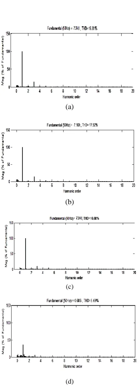
In the waveform the harmonic contents were reduced much and it appears as sinusoidal. The harmonic content in the neutral were almost eliminated and it shown as purely sinusoidal. The FFT analysis for unbalanced system was shown in Fig 7.
[image:5.595.59.282.75.413.2]
Fig 6 Simulation results for phase and neutral current with filter
(a)
(b)
(c)
(d)
Fig 7 FFT analysis of phase currents (a, b and c) and neutral current (d) for unbalanced before active filter
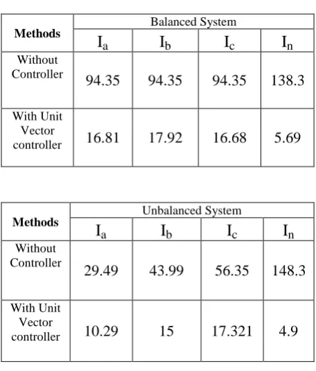
[image:5.595.56.275.533.712.2]TABLE I - THD VALUES IN % FOR BALANCED AND UNBALANCED SYSTEM
Methods Balanced System
I
aI
bI
cI
nWithout Controller
94.35
94.35
94.35
138.3
With Unit Vector
controller
16.81
17.92
16.68
5.69
Methods
Unbalanced System
I
aI
bI
cI
nWithout Controller
29.49
43.99
56.35
148.3
With Unit Vector
controller
10.29
15
17.321
4.9
5. CONCLUSION
The Novel control techniques based on Unit Vector Control for harmonics compensation in distribution system using series active filter was presented. The active filter inverter acts as a high impedance for the current harmonics in the neutral conductor. After compensation of series active filter in the neutral conductor, it was found that the harmonic content was much suppressed in both phase and neutral conductors. Therefore, the unity source power factor at the positive sequence fundamental frequency was achieved. The control scheme was presented for both balanced and unbalanced loading conditions for rectifier loads. The proposed system uses only one active filter, so it avoids the series/parallel resonance problem and complexity of the system was less. Simulation results and the THD values showed the effectiveness of the proposed method in the three-phase four-wire distribution
6. REFERENCES
[1]
T. M. Gruzs, “A survey of neutral currents in three- phase computer power systems,” IEEE Transactions on Industry Applications, vol.26, no. 4, pp. 719-725, July/August 1990.[2] P.N.Enjeti, W.Shireen, P.Packebush and I.J.Pitel, “ Ananlsis and Design of a new active power filter to cancel neutral current harmonics in three-phase four-wire electric distribution systems” , IEEE Transaction on Industrial Applicatiion, vol 30, pp. 1565-1572, Nov/Dec. 1994
[3] P. T. Cheng, Y. F. Huang, and C. C. Hou, “A new harmonic suppression scheme for three-phase four-wire distribution systems,” in Proc. IEEE APEC, vol. 2, 2001, pp. 1287–1293.
[4] H. L. Ginn III and L. S. Czarnecki, “An optimization-based method for selection of resonant harmonic filter branch parameters,” IEEE Transaction on Power Delivery., vol. 21, no. 3, pp. 1445–1451, Jul. 2006 [5] J. A. Pomilio and S. M. Deckmann, “Characterization
and compensation of harmonics and reactive power of residential and commercial loads,” IEEE Transaction on Power Delivery, vol. 22, no. 2, pp. 1049–1055, Apr. 2007.
[6] J. C. Das, “Passive Filters—Potentialities and Limitations,” IEEE Transaction on Industry Applications, vol. 40, no. 1, January/Febuary 2004 [7] Hurng-Liahng Jou, Jinn-Chang Wu, Kuen-Der Wu,
Wen-Jung Chiang, and Yi-Hsun Chen, “Analysis of Zig-Zag Transformer Applying in the Three-Phase Four-Wire Distribution Power System,” IEEE Transaction on Power Delivery, vol. 20, no. 2, April 2005
[8] M. Aredes, and E. H. Watanabe, “New Control Algorithms for Series and Shunt Three-phase Four-Wire Active Power Filters," IEEE Transactions on Power Delivery, vol. 10, no. 3, pp. 1649-1656 (1995)
[9] M. Ishihara, S. Mori, G. Nakagawa, and M. Nishitoba, “Development of active filter for three-phase four-wire system", Rec. SPC meeting of IEEJ, no. SPC-96-128, pp. 63-70 (1996) (in Japanese)
[10] M. Aredes, J. Hafner, and K. Heumann, “Three-phase Four-wire Shunt active Filter Control Strategies," IEEE Transactions on Power Electronics, vol. 12, no. 2, pp. 311-318 (1997)
[11] J. S. Lai, and T. S. Key, “Effectiveness of harmonic mitigation equipment for commercial buildings," IEEE Transactions on Industry Applications, vol. 33, no. 4, pp. 1104 -1110 (1997)
[12] P. Cheng, Y. Huang, and C. Hou, “Design of a neutral harmonic mitigator for three-phase four-wire distribution system," IEEE/IAS Annual Meeting, vol. 1, pp. 164-171 (2001)
[13] Conor A. Quinn, Ned Mohan, “A Four-Wire, Current-Controlled Converter Provides Harmonic Neutralization in Three-phase, Four- Wire Systems,” in Proc. IEEE APEC, vol. 1, 1993
[14] Z. Wang, Q. Wang, W. Yao, and J. Liu, “A series active power filter Adopting hybrid control approach,” IEEE Transaction on Power Electronics, vol. 16, no. 3, pp. 301–310, May 2001
[15] F. Z. Peng, H. Akagi, and A. Nabae, “A new approach to harmonic compensation in power systems-a combined system of shunt passive and series active filters,” IEEE Transaction on Industrial Applications, vol. 26, no. 6, pp. 983–990, Nov./Dec. 1990.
[17] Tadashi Fukami, Toshinari Onchi, Nobuyuki Naoe, , and Ryoichi Hanaoka,” Compensation for Neutral Current Harmonics in a Three- Phase Four-Wire System by a Synchronous Machine,” IEEE Transaction on Industry Applications, vol. 38,no. 5, September/October 2002 [18] Shigenori Inoue, Toshihisa Shimizu, and Keiji Wada,
“Control Methods and Compensation Characteristics of a Series Active Filter for a Neutral Conductor,” IEEE Transaction on Industry Applications, vol. 54, no. 1, Febuary 2007
[19] T.Chatchanayuenyong, T. Khamriang, A. Kantarawichai, “A Fast Series Active Filter using Sliding Mode Control to Correct and Regulate Unbalance Voltage in
Three-Phase System,” American Journal of Engineering and Applied Sciences 2 (2): 393-398, 2009
[20] F. Z. Peng and J. S. Lai, “Generalized instantaneous reactive power theory for three phase power system,” IEEE Transaction on Instrumentation and Measurement, vol. 45, no. 1, pp. 293–297, Feb 1996.