ORIGINAL RESEARCH ARTICLE
PERFORMANCE OF SYNCHRONOUS GENERATOR USING
PID -FUZZY LOGIC CONTROLLER
Mohan Krishna, C., Imrankhan, S. and Manohar
Assistant professor in ALITS ENGG College Anatapur
ARTICLE INFO ABSTRACT
This work aims to develop a PID controller tuned FUZZY controller, it functions such as maintaining of the terminal voltage of the synchronous generator constant even for the change in load, this is achieved by varying the field current flowing through the field coils of synchronous generator. It includes simulations for the justification of this design in MATLAB.
*Corresponding author
Copyright ©2017,Mohan Krishna et al.This is an open access article distributed under the Creative Commons Attribution License, which permits unrestricted
use, distribution, and reproduction in any medium, provided the original work is properly cited.
INTRODUCTION
The problem of voltage control in the system consists of the voltage control at the generating station in the system, i.e., voltage control of generators and transmission lines. The voltage of ac generators is controlled by voltage regulators working on electromechanical principle such as vibrating type regulator in which a fixed amount of resistance is cut in and cut out on the exciter field circuit, depending on the alternator voltage variation to maintain it constant. the main importance of this paper is to design a controller to overcome the difficulties of complex mathematical model of the plant to be controlled, and to develop an intelligent control system, so that the regulator becomes independent of the system to be controlled and it generates controlling signals on the bases of
experiences it faces during the operation. This critique work
carried out for the problem of load change on the synchronous generator and studies the terminal voltage variation with load change.
The objective of the present work is
Maintain the terminal voltage of the synchronous
generator constant inspite of the load change on it.
Run the synchronous generator in stable region i.e.,
limiting the transient state to last only few milliseconds when the load changes occur on the synchronous generator.
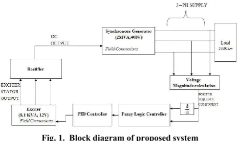
Proposed system
In large alternators, the excitation system is provided by a small synchronous machine connected on the same shaft as the main synchronous generator. Current rectification is performed by a rotating diode bridge mounted on the synchronous machine shaft, thus avoiding slip rings for providing DC power to the synchronous generator field. Mechanical coupling of the Synchronous generator and the Exciter is done by using speed as mechanical input for the Exciter machine. The Exciter is a small synchronous machine rated 8.1 kVA, 400 V, 50Hz, 1500 RPM. The Exciter output voltage would be 12 V. The output of the rectifier bridge is connected directly to the Synchronous generator field terminals. Filtering is not required because of the large field inductance. The
synchronous generator is a 2 M VA, 400V, 50 Hz, 1500
RPM machine driven by a diesel motor. A nominal field current of 100A specified in the mask parameters allows using
ISSN: 2230-9926
International Journal of Development Research
Vol. 07, Issue, 11, pp.16971-16976, November,2017
Article History:
Received 14th August 2017
Received in revised form 28th September, 2017
Accepted 03rd October, 2017
Published online 29th November, 2017
Key Words:
PID controller, Fuzzy controller, Synchronous generator.
Citation: Mohan Krishna, C., Imrankhan, S. and Manohar.2017.“Time-mortality relationship in marine ornamental harlequin shrimp hymenocera picta
against white spot syndrome virus using bacterially expressed recombinant envelope Proteins (VP39 AND VP28)”,International Journal of Development
Research, 7, (11), 16971-16976.
the real voltage applied to the rotor (not the field voltage seen from stator). It results in a nominal field voltage of 9.2837V. The voltage appearing across current source corresponds to the field voltage which must be applied to the field connections of Synchronous Machine input.
Design of control system for voltage control
To design a regulator control system in such a manner to overcome the difficulties of complex mathematical model of the plant to be controlled, and to develop an intelligent control system, so that the regulator becomes independent of the system to be controlled and it generates controlling signals on the bases of experiences it faces during the operation. Also the system should be very simple to understand, and easy to program.
Pid Controller
Regulator control systems mostly use PID controllers which are given by equation shown below
GC(S)=KP+KI/S+KDS
PID controllers are commonly used in industry and a large factory may have thousands of them, in instruments and laboratory equipment. In engineering applications the controllers appear in many different forms: as a standalone controller, as part of hierarchical, distributed control systems, or built into embedded components. Most controllers do not use derivative action. The ideal version of PID controller is given by
(t)=Kpe(t)+Ki
∫
0( )
+Kd [image:2.595.39.284.470.614.2]Where u is the control signal and e is the control error (e = r − y). The reference value, r, is also called the set point.
Fig. 1. Block diagram of proposed system
The control signal is thus a sum of three terms: a proportional term that is proportional to the error, an integral term that is proportional to the integral of the error, and a derivative term that is proportional to the derivative of the error. The controller parameters are proportional gain kp, integral gain ki and derivative gain kd.
Fig. 2. A PID Controller takes control action based on past, present and future predictions of future control errors
The transfer function of the PID Controller is shown below
The PID controller has two zeros and one pole. Generally an additional pole is required to limit the high-frequency gain . To develop the control law for fuzzy logic controller, which performs the function of PID control efficiently, the concept of digital PID is necessary. In case of digital PID controllers, the multiplication, integration and differentiation are performed numerically in digital computers. Users of control systems are frequently faced with the task of adjusting the controller parameters to obtain a desired behaviour. There are many different ways to do this. One way to do this is to go through the steps of modelling and control design. Since the PID controller has so few parameters a number of special empirical methods have also been developed. A simple idea is to connect a controller, increase the gain until the system starts to oscillate, and then reduce the gains by an appropriate factor. Another is to measure some features of the open loop response and to determine controller parameters based on these features. The PID controller is designed by using Ziegler and Nichols method.
PID TUNER
[image:2.595.308.563.477.657.2]PID Tuner provides a fast and widely applicable single-loop PID tuning method for the Simulink PID Controller blocks. With this method, you can tune PID controller parameters to achieve a robust design with the desired response time. To launch the PID Tuner, double-click the PID Controller block in MATLAB to open its block dialog. In the Main tab, click Tune.
Table 1. Default parameters of PID controller
Controller Kp/kc Ti/Tc Td/Tc Tp/Tc
P 0.5 1.0
PI 0.4 0.8 1.4
[image:2.595.54.269.697.780.2]PID 0.6 0.5 0.25 0.85
Fig. 3. PID response for default parameters
Displaying PID Parameters
After you are happy with the controller performance on the linear plant model, you can test the design on the nonlinear model. To do this, click Update Block in the PID Tuner. This action writes the parameters back to the PID Controller block in the Simulink model.
Fuzzy Logic
complex, that it is very difficult or even impossible to build exact mathematical model. Controllers of this type are characterized by large number of parameters, like: number and form of fuzzy sets used for division of computational domain of input and output signals, selection of operators for realizing fuzzy operations as sum, product and negation, selection of conclusion algorithm, choice of function for computing numerical values of output signals. These parameters must be adjusted and given the correct values in order to the controller work properly. Application of fuzzy logic in control process requires using the following elements: definitions of fuzzy sets, fuzzy logic operators, fuzzy rules (rule database), inference mechanism and algorithm of computing numerical values of output signal.
Fig. 4. PID parameters after tuning
The Fuzzy Control is characterized as
(i) Seven fuzzy sets for each input and output. (ii) Triangular membership functions for simplicity. (iii) Fuzzification using continuous universe of discourse. (iv) Implication using Mamdani’s, ‘min’ operator.
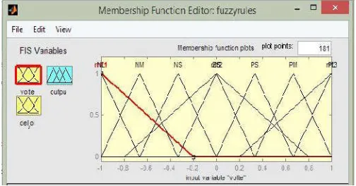
Fuzzification
[image:3.595.43.285.224.368.2]Membership function values are assigned to the linguistic variables, using seven fuzzy subsets: NB (Negative Big), NM (Negative Medium), NS (Negative Small), ZE (Zero), PS (Positive Small), PM (Positive Medium), and PB (Positive Big).
Fig. 5. Graph showing various membership functions
Inference Method
Several composition methods such as Max–Min and Max have been proposed in the literature. In this paper Min method is used. The output membership function of each rule is given by the minimum operator and maximum operator. Table shows rule base of the FLC.
Table 2. Rule Base
Modelling of Proposed System
[image:3.595.314.557.523.702.2]Case I: Proportional integral derivative Controller: In this case, we use the proportional integral derivative (PID) controller to control the excitation voltage of the synchronous generator . The proportional gain is set to 4, integral gain is set to 5, derivative gain is set to 0.1. In this circuit, we are mainly using PID controller, speed governor for prime mover (diesel generator),rectifier to convert ac obtained from the main synchronous machine to dc which is applied to rotor, another small synchronous machine which is acting as a exciter, 500kw base load and extra 1000kw load is taken into circuit with the help of circuit breaker closing.
Table 4. System Parameters when using PID Controller
SYSTEM PARAMETERS VALUES Main synchronous machine 2MVA
Exciter 8.1 KVA, 400V
Primary load 50KW
Secondary load 1000KW
Proportional gain 4
Integral gain 5
Derivative gain 0.1
Matlab Simulation Circuit -PID controller
Case II: Pid controller along with fuzzy logic
[image:3.595.36.288.562.694.2]logic controller, speed governor for prime mover (diesel generator), rectifier to convert ac obtained from the main synchronous machine to dc which is applied to rotor, another small synchronous machine which is acting as a exciter, 500kw base load and extra 1000kw load is taken into circuit with the help of circuit breaker closing.
Table 3. System parameters when using for PID Controller along with Fuzzy Logic
SYSTEM PARAMETERS VALUES
Main synchronous machine 2MVA
Exciter 8.1 KVA, 400V
Primary load 50KW
Secondary load 1000KW
Proportional gain 4
Integral gain 5
Derivative gain 0.1
Membership functions 7
Membership function Limit [-1 1]
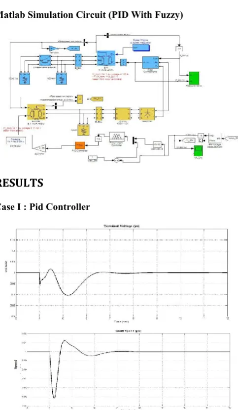
Matlab Simulation Circuit (PID With Fuzzy)
RESULTS
[image:4.595.69.257.167.267.2]Case I :Pid Controller
Fig. 6. Terminal Voltage and shaft speed represented in per unit
The above figure shows the terminal voltage of the synchronous generator measures in per unit for a base value of 400 volts. Assuming steady state before 3 sec, extra load of 1000KW is added on to the synchronous generator. This cause disturbance on the generator causing the terminal voltage deviates from the reference voltage (1 pu). It again gains its steady state after 3 sec at 7 sec time. The constant steady state
[image:4.595.41.283.268.683.2]error is almost zero. The shaft speed reaches the reference speed after 3 sec of adding of the 1000 KW load on to synchronous generator.
Fig. 7. Exciter Voltage and Exciter Current
The above figure shows the change in the exciter voltage when the load is added at 4 sec. It takes relatively long time to stabilize the exciter voltage but with a more voltage compared to the same and the stator current of the main synchronous generator. Initially when the load is at 4 sec, the stator current gets excess than what it need to be and decreases after 2 sec.
Fig. 8. Field Voltage and Field Current
The above figure shows the field voltage applied to the main synchronous machine. The field voltage gets disturbed slightly on addition of the load. It gets excess than required and lowers itself again after 3 sec. The above figure 5.15 shows the field current which is flown through the field coils of the main synchronous generator. At 4 sec, the load of 1000KW is added which necessitates the increase in the field current. The field current increases and stabilizes after 3 sec which more when compared to case I but with an added advantage of stabilizing at required value without much constant steady state error.
Case III: Pid controller along with fuzzy logic
[image:4.595.309.556.385.585.2]set to 4, integral gain is set to 5, and derivative gain is set to 0.1. In this circuit, we are mainly using PID controller, fuzzy logic controller, speed governor for prime mover (diesel generator), rectifier to convert ac obtained from the main synchronous machine to dc which is applied to rotor, another small synchronous machine which is acting as a exciter, 500kw base load and extra 1000kw load is taken into circuit with the help of circuit breaker closing.
[image:5.595.44.282.160.278.2]Fig. 8. Terminal Voltage represented in per unit (PID Controller with Fuzzy Logic)
Fig. 10. Shaft speed
The shaft speed reaches the reference speed after 2 sec of adding of load with much less oscillations compared to previous cases and settle to reference speed with a much lesser time delay.
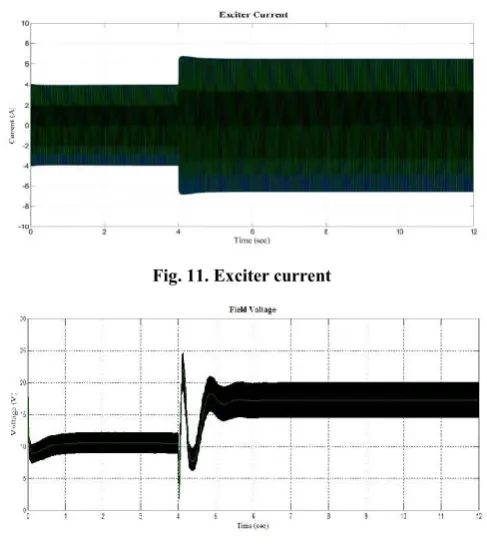
Fig. 11. Exciter voltage
The above figure shows the exciter voltage change when the load is added at 4 sec before which the exciter is in steady state. It takes approximately a little more than 1 sec to stabilize the exciter voltage.
The above figure shows the change of exciter current when the load is added at 4 sec. It takes no time to get the required current
[image:5.595.42.287.326.447.2]Fig. 11. Exciter current
Fig. 12. Field voltage
[image:5.595.316.552.396.519.2]The above figure shows the field voltage which is applied to the field coils and shows the change in it when the load is added at 4 sec. It takes 1 sec to stabilize the voltage.
Fig. 13. Field current
The above figure shows the change in flow of field current in the field coils when the load is added at 4 sec. It adapts very quickly in less than 1 sec to the required value to maintain the coupling between rotor and stator.
Conclusions
This paper includes a custom made PID Controller along with Fuzzy Logic to improve the performance of the synchronous generator. The performance improvement parameters include the following.
Maintaining of the terminal voltage of the synchronous
machine constant and unaffected by the load variations on it.
Supply of the required field current through the field
coils to have a stable magnetic coupling between stator and rotor.
Maintain the load angle within specified limits so as to
[image:5.595.45.287.542.673.2]Addition of the new Proportional Integral Derivative controller along with the Fuzzy Logic for the control of the field voltage of the exciter adjusts the field voltage to exciter according to the rules specified for the fuzzy supporting in addition to PID Controller regulates all the above mentioned parameters indirectly or directly.
Future scope
The proposed controller could also be used for control of speed of the shaft of the generator in place of the governor for the turbine to further more increase the effective performance of the synchronous generator. Other controlling techniques such as use of genetic algorithm, artificial neural networks, artificial intelligence can be used along with fuzzy logic or in place of fuzzy logic to increase the effectiveness of the controller in improving the parameters.
REFERENCES
Afshan Ilyas, Shagufta Jahan, "Tuning of Conventional PID and Fuzzy Logic Controller using different Defuzzification Techniques " , ISSN 2277-8616.
Anant Oonsivilai, Padej Pao-la-or, " Optimum PID Controller tuning for AVR System using Adaptive Tabu Search " , School of Electrical Engineering, Suranaree University of Technology, Nakhon Ratchasima, Thailand.
Besheer, A. H. Bensenouci, A. 2012. " Voltage and Power Regulation for a Sample Power System using Ant Colony
System Based PID Controller " , International Electrical
Systems, J. Electrical Systems 8-4 (2012):397-410
Gowri Shankar Kasilingam and Jagadeesh Pasupuleti, " Tuning of PIC Controller for a Synchronous Machine
Connected to a non-linear load " , ARPN Journal of
Engineering and Applied Sciences", VOL. 9, NO.
9,September 2014.
Habibur Rahman, Dr. MD. Fayzur Rahman, " Stability Improvement of Power System by using SVC with PID Controller " , ISSN 2250-2459, VOL. 2, Issue 7, July 2012. Kiyong Kim, Richard C. Schaefer, " Tuning a PID Controller for a Digital Excitation Control System " , IEEE Transactions on Industry Applications, VOL. 41, NO. 2, March/April, 2005.
O ' Dwyer , Aidan, " Performance improvement using simple PID controller tuning formulae " , Proceedings of 3rd IET International Conference on Power Electronics, Machine and Drives, Dublin.
Ritu Shakya, Kritika Rajanwal, " Design and simulation of PD, PID and Fuzzy Logic Controller for Industrial Application " , SRMSCET, Bareilly, India.