TOP of text, page 2 and following pages, aligned to line
Case Study: Using ADLARS to Design and Develop a
Real-Time Network Emulator
R. Bashroush*, A. Al-Nemrat*, M. Bachrouch*, I. Spence^
* School of Computing, IT and Engineering, University of East London, UK
{rabih, ameer}@uel.ac.uk
^School of Electrical, Electronic Engineering and CS, Queen’s University Belfast, N. Ireland
Abstract. As testing and benchmarking performance of web services and networked applications has proven to be cost-effective, and crucial in some applications, increased significance has been attached to the development of hardware and software network emulators and simulators. In this paper, we discuss a possible design of a light-weight real-time IP network emulator that can provide the same functionality and performance as hardware simulators. Also, as the systematic software engineering discipline has become a necessity in the software development life-cycle, we present a possible approach, utilizing mature software engineering disciplines, for building the software architecture of the emulator. We then use ADLARS [1], an Architecture Description Language for Real-time Systems to describe the architecture. The emulator’s architecture serves as a good test-bed for our ADL because of its real-time and concurrent nature. We conclude by testing our design and presenting a possible JAVA implementation of the emulator over a UNIX system.
1. Introduction
Simulation and Emulation play a crucial part in the development life cycle of many networked applications and web services as well as in protocol design. This is because they allow laboratory based testing and performance benchmarking, which is sufficiently close to real-life to provide useful information.
In the domain of Simulation, there has been a lot of work done through open source projects like the Network Simulator NS-2 [2] which is a discrete event simulator targeted mainly for research networks, to commercial products like OPNET [3] that is one of the most popular Simulation tools in the market. Simulators are based on the idea of modeling the real-world environment and protocols. And with modeling arises some traditional problems like the difficulty involved in modeling complex environments which is sometimes impossible to do resulting in the need for approximation. Another
problem is the high learning curve usually associated with operating the tools.
As for emulators, they do not use the concept of modeling, but instead operate on real networks and machines. There are many kinds of emulators available; some of them are application specific such as Raddel [4] which is best used to test network management systems. Others target specific operating environments, for example ONE [5] is an emulator that runs over Solaris and emulates the link between two interfaces on the same machine. Also Dummynet [6] falls into this category which is a FreeBSD kernel extension. Yet again, some emulators are limited only to specific attributes. An example of this is ENDE [7] which is an end-to-end network delay emulator.
In the paper we describe a light-weight emulator that utilizes third party virtual interface applications (like TUN Driver [8] over UNIX) and does not have many of the limitations mentioned above. It can emulate a wide range of network characteristics like: packet classifier, bandwidth limiter, delay, jitter, packet loss, burst drop, re-order, duplicate, multi-path effects, queuing, etc. Additionally, it can run over any operating system (assuming the availability of third party software that can provide the virtual interface to the userland application to write to and read from). Our emulator is also transparent to the user application in the sense that it doesn’t impose any extra modifications on the operating system or the user application (such as recompilation with extra libraries, etc.).
design and present a working JAVA implementation of the emulator over Solaris. Section 6 concludes and highlights future work.
2. The Emulation Framework
This section presents the overall picture of the evaluation framework and explains the different blocks.
The framework consists of three parts: the application to be tested; the third party virtual interface software; and the emulator. The emulation process can be utilized with one or more machines based on the nature of the application tested.
For our emulator to assess the effects of particular network characteristics on a real-time connection, we need to intercept ongoing communication packets, expose them to the different effects/characteristics (that are set through a setup file read by our emulator or through a GUI), and then send them to their desired destination.
We will show first how the IP packet interception takes place with the help of the virtual interface application. Then we will explain how our emulator would apply different effects to the intercepted packets with the help of an example.
As the interception of packets is a kernel dependent process, this service is usually provided by kernel extensions or third party software that differs according to the specific OS we are using. To better understand the process, we will take a specific example and build upon it throughout this section. For our example, we will take Solaris as the operating system and TUN Driver [8] to act as the packet interceptor. TUN Driver is a virtual P2P network device that provides low level kernel support for IP tunneling. The Driver can create virtual Ethernet devices on the local machine and map them to virtual IP addresses. It also provides two interfaces: one character device (dev/tunX) for user application access, and another virtual P2P interface (tunX) for kernel access.
So, if the OS writes an IP packet to tunX, it can be read by the user application from dev/tunX. The same thing happens if the user application writes an IP packet through dev/tunX, it will appear to the OS on tunX (as if coming from a real network through the virtual interface).
Let us assume that we have two machines, one called Glen with IP address 143.117.60.123 and another called Fujin with IP address 143.117.60.100. We want to test
the performance of the telnet application over a link with specific characteristics.
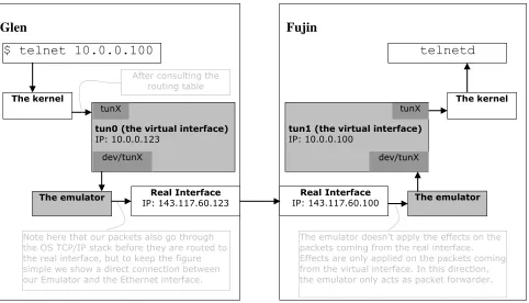
When we telnet from Glen to Fujin, the emulator needs to intercept the communication and apply the desired effects. To do so, it needs the help of one of the virtual Ethernet interfaces (created in our case by the TUN Driver [8]). By making the OS forward the packets to the local virtual interface (let’s call it tun0) instead of the real interface when sending the specific application data (telnet in our case), the emulator can then intercept the packets (by reading them on the dev/tunX interface of tun0), apply the desired effects (we will see how later) and then send them through UDP to the real destination, (Fujin). The emulator on Fujin would then receive the packets and hand them over to the operating system through the dev/tunX interface of tun1 (the virtual interface) on Fujin. With this scenario, we would have utilized the TUN Driver in a novel way to serve our emulation framework and the result is an emulated network that is totally transparent to the operating systems as well as the telnet application.
To see how to allow the above configuration, (and continuing with the same example) let us say tun0, the virtual Ethernet interface on Glen, is given the virtual IP address: 10.0.0.123, and tun1, the virtual Ethernet interface on Fujin, the virtual IP address: 10.0.0.100. By setting the routing table on Glen to forward all the packets going to 10.0.0.100 (what will be virtual Fujin) to 10.0.0.123, all the packets sent to 10.0.0.100 will go through tun0 and then to the emulator. The same configuration would be applied on Fujin to enable two-way communication. The routing table on both machines would like figure 1 below.
Routing table on Glen:
+---+ |Destination | Gateway | Interface| +---+ |10.0.0.100 |10.0.0.123 | tun0| +---+
Routing table on Fujin:
+---+ |Destination | Gateway | Interface| +---+ |10.0.0.123 |10.0.0.100 | tun1| +---+
So, to telnet from Glen to Fujin and let the IP traffic go through our emulator, we type: telnet 10.0.0.100. This way the operating system will forward the traffic to tun0 (on Glen) that hence allow the emulator to read it from dev/tunX, apply the required effects, and send it on to Fujin using UDP on the real Ethernet interface. The emulator on Fujin would receive the packets, send them to tun1 (through dev/tunX) and the packets would look to the operating system as if they were coming from a real network experiencing the effects imposed by the emulator (delay, jitter, etc.). Figure 2 below summarizes the whole emulation framework.
We could wrap the TUN Driver with a script (which would read the IP addresses from the user) that starts a virtual Ethernet interface (tun0, tun1, etc.) and adds the proper entries to the routing table. It would also provide the user application access to dev/tunX without the need for super user privileges.
The same scenario could be applied to other OS’s given the appropriate third party virtual interface application.
3. Architecture Description Language for Real-time Systems (ADLARS)
ADLARS [1] is an architecture description language that was developed within our group to support the description of real-time software architectures. It can be used to describe the architecture of families of related systems, and has facilities which allow the relationships between the system features and its architecture to be
explicitly defined.
This section presents a brief introduction to the language to enable understanding of the terminology used in the following section, for more details about the language please refer to [1].
The language, as described in [1], views Software Architectures to be existing in a three dimensional space: concurrency, structure and behavior, and provides the necessary capabilities to capture these dimensions. Concurrency is conveyed in Tasks in ADLARS. Tasks are concurrently executing units that communicate through given ports using pre-described protocols and events. Events fall into different kinds called event categories. Event category provide information about a certain type of events, like an event’s bandwidth. Tasks usually contain information like: Interaction themes, Features supported, Components and Input/Output alphabets. Interaction themes [9] are used to partition a Task’s interface (or port) into multiple planes each of which is concerned with a specific theme. There are several benefits for using interaction themes such as separation of concerns, reuse, controlled propagation of changes etc. The Features supported section contains a list of features from the candidate architecture’s feature model. Features are classified into mandatory (always supported by the Task) optional (may or may not
Glen
Real Interface
IP: 143.117.60.123
tun0 (the virtual interface)
IP: 10.0.0.123
$ telnet 10.0.0.100
The kernel
The emulator
tunX
dev/tunX
After consulting the routing table
Note here that our packets also go through the OS TCP/IP stack before they are routed to the real interface, but to keep the figure simple we show a direct connection between our Emulator and the Ethernet interface.
Fujin
telnetd
tun1 (the virtual interface)
IP: 10.0.0.100
dev/tunX
RealInterface
IP: 143.117.60.100 The emulator
[image:3.612.68.550.443.719.2]The emulator doesn’t apply the effects on the packets coming from the real interface. Effects are only applied on the packets coming from the virtual interface. In this direction, the emulator only acts as packet forwarder.
Figure 2. An overview of the Emulation framework. The arrows show the path traversed by packets traveling from Glen to Fujin. To see how the packets travel from Fujin to Glen, just reverse the arrow directions.
The kernel
be supported by the Task), and alternative (alternative features). The Components section is used to describe the passive internal components which produce the functionality that is invoked by the Task in response to arriving events. The Input/Output alphabets section of the Task lists the accepted and generated events by the task with their corresponding rates of occurrence.
Structure, on the other hand, is described by Components which form the basic building blocks of ADLARS architectures. Component descriptions provide information on the related interaction themes to supported features, sub-component architecture, and interface. As for interaction themes and features supported, they contain similar information to the interaction themes and features supported sections in Tasks. The Sub-components section is similar to components in Tasks. The Arrangements section describes the way sub-components are connected within a component with the capability of making use of existing design patterns like façade, service-provider etc. The interface section describes the interface of a component in terms of services provided and required by the component given that the component is in a certain state (temporal state).
And finally, behavior is captured within interaction themes. As we previously mentioned, each interaction themes bundle a part of the system’s interactions that are concerned with a specific behavior. For more information on the exact conceptual background and the semantic environment refer to [1].
4. Designing the Software Architecture of the Emulator
At the moment, the process of developing software architectures is frequently ad-hoc, with each company or research group following its own developed discipline in its production line. The phases of developing software architecture make use of the feature model as a starting point, and proceeds in the following main phases:
Phase 0: Designing the feature model of the system.
Phase 1: Designing the ADLARS Tasks and the Event Categories (system events). This is a recursive procedure that would require changes to the feature model and the Tasks recursively. Different small testing scenarios might be used to increase confidence in the basic correctness of the task in development.
Phase 2: Designing the Components. This is a recursive procedure that might require changes to the existing Tasks or feature model (e.g. if you find that two different Components that you put in the same Task require two separate threads of
execution, this would require a restructuring of the design). This may also require changes to the above layers.
Phase 3: Designing the Sub-Components (if needed). This as well might impose changes to the above layers (Components, Tasks and Feature model).
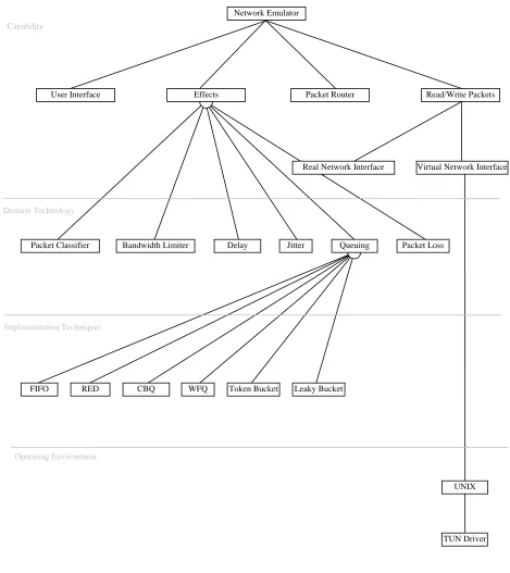
In phase 0 we use a feature modeling strategy which is similar to FORM [11] an extension to FODA (Feature Orient Domain Analysis) [10] to capture the system requirements. As described in [11], FODA and FORM are tools used to capture design requirements and attributes (Features) of the system that directly affect end-users. The end-users have to make decisions regarding the availability of features in the system. A feature model represents the standard features of a family of systems in the domain and the relationships between them. Alternative (represented with a semicircle) or optional (represented with a circle) features must be indicated in the feature model. Alternative features can be thought of as specializations of a more general category. There are four different types of features:
Capability: The capabilities of applications in a domain from the end-user’s perspective.
Operating Environment: The operating environments in which applications are used and operated.
Domain Technology: The application domain technology based on which requirements decisions are made.
Implementation Techniques: The implementation techniques (e.g., The way a buffer’s data structure is implemented, RED, CBQ etc.).
For more information about FODA and FORM please read [10][11]. Part of the final version of the feature model generated for our emulator is shown in figure 3 below.
After going recursively through phases 1, 2 and 3, the final architecture of the emulator consisted of:
a) Four Tasks:
1. tPacketRouter: Forwards a given packet to the
appropriate output port based on preset rules
2. tSendReceive: Sends and receives packets
3. tEffects: Applies preset effects on incoming packets (delay, jitter, drop, etc.)
Network Emulator
User Interface Packet Router Read/Write Packets
Packet Classifier Bandwidth Limiter Delay Jitter Packet Loss
FIFO RED CBQ WFQ Token Bucket Leaky Bucket
Real Network Interface Virtual Network Interface
UNIX
TUN Driver Queuing
Effects Capability
Domain Technology
Implementation Techniques
[image:5.612.74.543.113.640.2]Operating Environment
b) Eight Components:
1. cForwardPackets: It enables the forwarding
functionality in a Task. It forwards a given packet from a given input port to a given output port
2. cBuffer: A Buffer functionality
3. cModify: The ability of modifying a specific bit in a given packet
4. cRoute: Packet routing functionality (between
ports)
5. cEffects: a wide range of effects that could be applied on a given packet.
6. cSetNetworkConfiguration: the ability to set the different virtual IP address if our emulator is intended to act as a wrapper as well to the third party virtual Ethernet interface (e.g. TUN Driver)
7. cSetEffectsAttributes: The ability to set the different effects and their values. For example whether to apply delay on the packets and the value of the delay in ms.
8. cGetNetworkStatistics: The ability to show different network statistics (average drop rate, delay, etc.)
c) Fourteen sub-components (Due to space limitation, we are only listing the sub-components. Their names were made as self-descriptive as possible of the function they do): scListener, scSender, scDecodeIPpacket scDecodeTCPpacket, scDecodeUDPpacket, scDecodeIPXpacket, scDecodeNCPpacket, scDecodeNetBiospacket, scCodeIPpacket, scCodeUDPpacket,
scCodeTCPpacket, scCodeIPXpacket, scCodeNCPpacket, scCodeNetBiospacket.
d) And two event categories:
1. setVar: the event sent to set a certain variable 2. IPpacket. An IP packet datagram
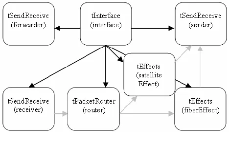
The ADLARS concurrent view of the emulator’s architecture is shown in figure 4. A sample ADLARS code snippet showing the engine layer is shown in figure 5.
Gray arrow means an IPpacket event
Black arrow means a setVar event
Figure 4. ADLARS visual representation
systemDescription() {
// creating instances of the tasks
tSendReceive forwarder(), sender(), receiver(); tInterface interface();
tPacketRouter router();
tEffects satelliteEffect(), fiberEffect();
//connecting instances using event category
connect(interface.port1, forwarder.port1)using(setVar); connect(interface.port2, sender.port1)using(setVar); connect(interface.port3, receiver.port1)using(setVar); connect(interface.port4, router.port1)using(setVar); connect(interface.port5,
satelliteEffect.port1)using(setVar);
connect(interface.port6, fiberEffect.port1)using(setVar); connect(receiver.port1, router.port1)using(IPpacket); connect(router.port2,
satelliteEffect.port1)using(IPpacket);
connect(router.port3, fiberEffect.port2)using(IPpacket); connect(satelliteEffect, receiver.port2)using(IPpacket); connect(fiberEffect.port3,
receiver.port3)using(IPpacket); }
Figure 5. ADLARS code snippet
The design did not cover all possible network protocols, but it does embrace a number of the more common ones. However, the plug and play capability of the architecture means that it is easy to create or use OTS components for your desired protocol (or operating system) and plug it in the architecture to add support for your environment. This demonstrates two of the main advantages of ADLARS which are the strong support for modifiability and portability.
5. JAVA implementation and Testing of the Emulator Design
This section describes an implementation of the emulator we developed using JAVA. First we present a detailed list of the different JAVA classes we generated. Second we present different techniques we used for evaluating the precision of the attributes of our emulator. We have tested our emulator over a Sparc Solaris 2.7 machine.
In what follows we describe the different JAVA classes we developed based on the ADLARS architecture of the system.
Main.java: the main thread of execution that holds the global variables and starts the different listeners as well as the GUI.
GUI.java: the graphical user interface of the system that enables the setting of the different emulation variables. See figure 6 below.
[image:6.612.61.295.518.664.2]
Figure 6.The AWT GUI of the emulator
Queue.java & Node.java: A queue of node objects with classical queue functionality. The node object contains: the IP packet received, and a timestamp. The queue acts as the emulator input buffer.
BufferListener.java: A thread of execution that extracts objects from the buffer (the queue) when they are available and hands them over to packetswitch.java
Packetswitch.java: This class receives packets from the buffer, decodes them with the help of the appropriate decoder (IP.java for example) and sends them to the proper effects object (Effects.java) based on the value of certain IP header data. For example, you can send all TCP data or all the data coming from a certain port (e.g. 21) to undergo specific effects. This provides our emulator with the capability of emulating complex networks comprising packet classification attributes (e.g.: QoS, multi-path effects, etc. )
Effects.java: This is the main class that applies the different effects on the packets. Among the effects we implemented: Bandwidth limitation, Jitter, Packet drop, Burst drop, Packet loss, Packet duplicate. For example, bandwidth limitation code snippet looks like:
T = packet_size_in_bytes * 8 * 1000 / bandwidth bandwidth is set by the user and by holding the packet T milliseconds, the emulated connection bandwidth will be limited to the user set value bandwidth
And jitter (random delay) is implemented as follows:
Lower_limit = mean – 3 * standard_deviation; Upper_limit = mean + 3 * standard_deviation; Width = Upper_limit – Lower_limit;
Delay = mean + Width * Math.random();
The standard_deviation and mean are set by the user, considering it to be normally distributed (varying between Lower_limit and Upper_limit), jitter effect is emulated by holding the packet Delay milliseconds
IP.java: this class carries the different information in the IP header to enable the decoding and encoding of the packets. This is useful when you want to set/Modify different fields of the IP header or implement packet classification based on data in the IP header.
Note: To run the emulator with a different protocol suite, or to enable modifications to the TCP payload, you need to implement the appropriate JAVA class.
Interface.java: A thread of execution that creates the different network sockets. It also enqueue incoming packets in the buffer and send packets after undergoing the required effects.
Now to test the performance of different attributes of our emulator, we used different techniques. For example, for testing the bandwidth limitation attribute we used the bing command [12]. The result is shown below (the user-set bandwidth is 24000bps):
--- estimated link characteristics --- estimated throughput 24084bps
minimum delay per packet 23.060ms (555 bits) average statistics (experimental) :
packet loss: small 0%, big 2%, total 1% average throughput 24159bps
average delay per packet 24.798ms (595 bits) weighted average throughput 23841bps
From the above, we can see how precise the result is given the small number of packets sent during the test and the induced delay by the JAVA Virtual Machine JVM (this delay can be estimated - around 25 ms in our system - and eliminated in the calculation of delays in the emulator to get better precision results).
Delay and Packet loss are tested in the same way, and the error was in the range of 0.001.
----10.0.0.100 PING Statistics----
32 packets transmitted, 32 packets received, 0% loss
round-trip (ms) min/avg/max = 170/235/300
Subtracting the approximate VM induced delay and dividing by two to get the one-way trip values, the result would be min/avg/max = 72.5/105/125 less than 0.05 error given that only 32 packets were used in the experiment. Almost 100% precision can be attained with 100 or more data packets.
6. Conclusion and Future Work
This paper presented a novel design of a light-weight network emulator and the different stages involved in producing its formal architecture. A sample instantiation of the architecture using JAVA was then developed and methods for testing different attributes of the emulator were presented.
With this simple and precise emulator design, complicated network properties can be emulated. From asymmetric ADSL links to variable bandwidth environment affected satellite links. The presence of separate buffers with separate Effects objects allows the emulation of multi-path environments and packet classification.
The paper also presented a brief description of ADLARS [1], an architecture description language developed within our research team.
The case study, in addition to producing a useable architecture for the emulator, helped us in fine tuning and testing our architecture description language (ADLARS) which is under on-going development.
Also, this case study will serve as part of the test-bed for experimenting with our ideas and research in the domain of Software Architecture [14][15] and Product Lines [16].
References.
1. R. Bashroush, I. Spence, P. Kilpatrick, and T.J. Brown. ADLARS: An Architecture Description Language for Software Product Lines. Proceedings of the 29th NASA/IEEE Software Engineering Workshop, Greenbelt, MD, USA, 6-7 April, 2005.
2. The Network Simulator, ns-2. http://www.isi.edu/nsnam/ns/
3. OPNET,
http://www.opnet.com/products/modeler/home.html
4. Raddel: A Network emulation framework by sourceforge.net, http://raddle.sourceforge.net/
5. ONE: The Ohio Network Emulator, OHIO University, http://irg.cs.ohiou.edu/one/#manual
6. L. Rizzo, Dummynet: a simple approach to the evaluation of network protocols. ACM Computer Communication Review, 1997.
7. I. Yeom, ENDE: An End-to-end Network Delay Emulator. Master's thesis, Texas A&M University, College Station, TX, 1998.
8. TUN Driver: A Virtual Point-to-Point Network Device, http://vtun.sourceforge.net/tun/
9. Mehdi Jazayeri, Alexander Ran, Frank van der Linden: Software Architecture for Product Families: Principles and Practice, Addison Wesley Longman, 2000.
10. KC Kang, SG Cohen, JA Hess, WE Novak, AS Peterson: Feature-Oriented Domain Analysis (FODA) Feasibility Study. Technical Report, CMU/SEI-90-TR-21, ESD-90-TR-222, Nov 1990.
11. KC Kang, S. Kim, J. Lee, and K. Kim: FORM: A Feature-Oriented Reuse Method with Domain-Specific Reference Architectures. Annals of Software Engineering, Vol. 5, pp. 143-168, 1998.
12. bing, http://fgouget.free.fr/bing/bing_src-readme.shtml
13. ping, http://fgouget.free.fr/bing/ping_src-man.shtml
14. R. Bashroush and I. Spence. "An Extensible ADL for Service Oriented Architectures. In: Papadopoulos G.A., Wojtkowski W., Wojtkowski W.G., Wrycza S., Zupancic J. (eds.), Information Systems Development - Towards a Service-Provision Society, Springer-Verlag, New York, ISBN 978-0-387-84809-9, September 2009.
15. R. Bashroush, I. Spence, P. Kilpatrick, and TJ Brown. "Towards More Flexible Architecture Description Languages for Industrial Applications," V. Gruhn and F. Oquendo (Eds.): EWSA 2006, Lecture Notes in Computer Science, Volume (4344), pp. 212-219. Springer-Verlag Berlin Heidelberg, 2006.