Efficiency of Daylighting in a Building -A Case Study
I.Rohini
1M.Prabu
2A.Karuppaiya
31,2,3
Assistant Professor
1,2,3
Jeppiaar SRR Engineering College,
Chennai, Tamil Nadu, India
Abstract—Daylight should be used as primary light source in building in daytime and fulfil both our visual and nonvisual (biological)needs. Sick building syndrome is largely related to air quality and indoor pollution, but also takes into account the availability of natural light, which studies show is vital for people's health and wellbeing. The health effects of natural light and fresh air offered by windows are pivotal to the health of a home and its inhabitants. A lot of the research that relates to the health benefits of natural light relates to night shift workers in particular, because they are working in an environment without natural light, which suppresses their serotonin levels (which affects their happiness), and melatonin levels (which affects their sleeping and relaxation). A lack of exposure to natural light can even lead to seasonal affective disorder, or the ‘winter blues’, which can then lead to clinical depression. Good lighting will provide a suitable intensity and direction of illumination on the task area, appropriate colour rendering, the absence of discomfort and, in addition, and a satisfying variety in lighting quality and intensity from place to place and over time. The argument for day lighting in buildings therefore has three strands:
• it provides a healthier and more enjoyable indoor climate • it conserves the earth’s resources
• because it saves energy, it saves money. This research work involves checking of lighting efficiency in a building by taking onsite measurements and compare with the protractor method.
Key words: Day Lighting, Protractor Method, Onsite
Measurements, Lux Meter, Sick Building Syndrome
I. INTRODUCTION
A. General
In the present energy scenario in India where gap between demand and supply of electrical energy is continuously increasing, the escalation in cost of power and associated environmental concerns have created awareness about efficient use of energy in every walk of life. Since, building sector is a major consumer of electricity, it is imperative to envelope building designs that would utilize solar and wind energy to the fullest possible extent for ameliorating thermal environment indoors [1].The focus of these areas is directed towards improving energy efficiency in existing buildings and development of codes so that new buildings to be designed and built with energy efficiency [1]. This is a testimony to the fact that necessity for design of functional and energy efficient buildings has been very well recognized and efforts are needed to design buildings that would function in conformity with climate and not zoning the country into regions in such a way that the difference of
and there also appears to be very little incentive for buildings to be operate more efficiently.
By adopting more modern and energy efficient technologies and practisers, potential designers, builders and end users in Asian developing countries should gain comparative advantages while avoiding mistakes of the industrialized world [2]. However, there are several barriers hindering them from bracing energy efficiency options in their buildings. Good lighting is necessary for all buildings and has three primary aims:
To promote the work or other activities carried on within the building
To promote safety of people using the building
To enhance the environmental quality and the energy efficiency of the building
To create, in conjunction with the structure and decoration, a pleasing environment conductive to interest and a sense of well-being.
B. Aim of Research
To do the energy auditing to determine the lighting deficiency of the building.
To take onsite measurements to determine the Establish local design sky illumination.
To determine the necessary daylight factor for the building.
Compare with the Standards given by BSCP.
Manipulate the design variables to achieve the required daylight factor.
II. METHODOLOGY
A. Case Study
Fig. 1: Ground floor plan of case study
Fig. 2: First floor plan of case study
Fig. 3: Second floor plan case study
B. Day lighting Analysis
The daylighting analysis can be carried by any of the following methods:
On-site measurements (e.g. using lux meter) and calculate DF.
Nomographs or charts (e.g. daylighting protractors) Computer programs (e.g. RADIANCE, Lumen Micro,
Lightscape, LightCAD)
The method taken in the present study in on site measurement using Luxmeter and the Nomographs and daylighting protractor.
C. On-site measurements
Procedure for analysis
Take on site measurements using Luxmeter as shown in Figure
Establish the minimum illumination level (Ei) Establish local design sky illumination (E0)
Calculate the necessary daylight factor using the formula [4] given below
DF = Ei /E0 × 100 Where
Ei is the minimum illumination level in Lux E0 is the local design sky illumination in Lux (Ei = 8000 Lux
for Warm – Humid climate) Compare with the Standards.
Fig. 4: Lux meter
D. Determination of Daylight factors:
Day lighting analysis using Lux meter has been carried out for four months from the month of September. Minimum illumination level for the four months have been measured and presented in the Table 1 below. Minimum of four months is taken as the Ei value. The local sky illumination E0 is taken as 8000 Lux for Warm-humid climate. The day light factor is determined, compared with recommended value and the deviations are found out and reported in the table. Minimum Daylight factor goes up to 0.3% and maximum reaches to 2.8%. The standard used for comparison is given by “British Standard code of Practice”
Location Sep Oct Nov Dec Ei Lux
E0
Lux DF % Req. value Deviation
Ground floor 130 100 90 120 90 8000 1.1 2 0.9
First floor 90 70 30 50 30 8000 0.3 2 1.7
Second floor 160 110 100 120 110 8000 1.3 2 0.7
News reading section 260 220 210 230 210 8000 2.6 2 0.6
Table 1: Values of Day light factor by Site measurements for case study
E. Protractor method
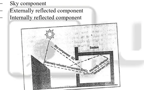
In the case of light falling on to a point, it can be broken down into three components
Sky component
[image:3.595.57.542.54.580.2] Externally reflected component Internally reflected component
Fig 5: Components of Diffuse Light Falling on work Plane in a room
The component usually falls as shown in Figure 5.14 [1]. Daylight factor is nothing but the sum of these components and can be expressed as follows.
DF = SC+ IRC + ERC
F. Determination of Sky Component
Take the section of the room, draw the working plane and on it the point to be considered (O) as in Figure 5[1].
Connect the limits of aperture to point o i.e., the lines PO and RO.
Place the protractor with a scale a uppermost, baseline on the working plane with the centre on point O. R3ead the values where lines PO and RO intersect the
[image:3.595.305.538.211.584.2]perimeter scale: the difference of the two values is the
Fig 6: Use of Daylight protractor to evaluate the Sky Component
Connect the limits of aperture with point O, i.e., MO and NO.
Place the protractor with scale B towards the window, base line parallel to the window with the centre on point O.
[image:3.595.46.293.343.499.2] If the two intersection points are on the either side of the centre line, add the two values obtained: if they are on the same side, take the difference of the two values. This will be a correction factor.
Multiply the initial SC by the correction factor to obtain the sky component. If there are no obstructions outside the window, there will be no ERC. If however, there are objects will reach the point considered, and will contribute to the day lighting, particularly in crowded urban situations. The magnitude of this contribution is expressed by the ERC, which can be found as follows. Find the equivalent SC, which would be obtained from
the same area of sky were it not obstructed, following the steps described above.
Multiply this value by 0.5 times the average reflectance of obstructing surfaces, or if this is unknown, by a factor of 0.2.
G. Determination of Internally Reflected Components (IRC)
Much of light entering through the window will reach the point considered only after reflection from walls, ceiling and other surface inside the room. The magnitude of the contribution to the day lighting of the point considered is expressed by the IRC. This will normally be fairly uniform throughout the room, thus it is sufficient to find the average IRC value. The simplest, method uses the nomogram given n Figure 6[1]. Steps to be taken in with nomogram are as follows:
Find the window area and find the total room surface area (floor, ceiling and walls, including windows) and calculate the ratio of window to total surface area. Locate this value on scale A of the nomogram.
Find the area of all the walls and calculate the ratio of wall to total surface. Locate this value in the first column of the small table (alongside the nomogram). Locate the wall reflectance value across the top of the
table and read the average reflectance at the intersection
of column on line. Or calculate an area – weighted mean reflectance (assume glass reflectance is 20%). Locate the average reflectance value on scale B and lay
a straight – edge from this point across to scale A (to value obtained in Step 1).
Where this intersects scale, read the value which gives the average IRC if there is no external obstruction. If there is an external obstruction, locate its angle from
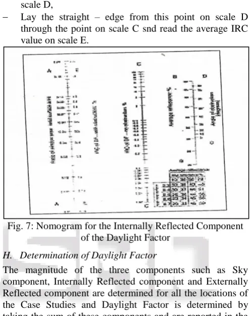
the horizontal, measured at the centre of window, on scale D,
[image:4.595.304.552.161.474.2] Lay the straight – edge from this point on scale D through the point on scale C snd read the average IRC value on scale E.
Fig. 7: Nomogram for the Internally Reflected Component of the Daylight Factor
H. Determination of Daylight Factor
The magnitude of the three components such as Sky component, Internally Reflected component and Externally Reflected component are determined for all the locations of the Case Studies and Daylight Factor is determined by taking the sum of these components and are reported in the Table 5and Table 6.
Location Sky component
(SC) % Internally Reflected component (IRC) % Externally Reflected component (ERC) %
Day light factor DF=SC+IRC+ERC
Ground floor 0.2 1.19 0.04 1.43
First floor 0.1 0.52 0.02 0.64
Second floor 0.1 1.29 0.06 1.65
News reading
section 0.3 1.74 0.18 2.82
Table 2: Values of Daylight Factor by Protractor Method for Case Study
III. RESULTS & CONCLUSIONS
1) Building health survey explains that most of the people suffer problems like eye irritation, throat infection, headaches, lack of concentration, fatigue, skin dryness etc due to improper lighting, poor ventilation and excess heat in summer in both the Case Studies. 80% of people participated in the survey reported at least one of these symptoms.
2) Temperature control (78 percent) and ventilation (66 percent) were the most common problems ever noticed by respondents.
3) Drafty conditions were reported by 75% of the respondents, 14 of whom (70 percent) noted that the conditions still exist. It shows that it is necessary for evaluating the building for comfort.
4) The minimum daylight factor for all the locations is determined by both the methods and compared with the standards.
5) In most of the classrooms daylight factor is found to be less than the recommended value.
6) Minimum Daylight factor goes up to 0.3%. Day light could be adopting the following systems.
the ceiling and deeper into a space. Matte finishes are better than specular surfaces for good distribution of daylight because they reduce reflected glare (hot spots).
8) Interior windows, transoms, and translucent or transparent interior partitions allow daylight to pass through to other spaces.
9) Blinds that rise from sill level, rather than drop down from above can be used to reduce backlighting and glare on work surfaces while still allowing daylight to penetrate deeply into the room through the unshaded upper part of windows.
10) Desirable reflectance’s such as ceilings>80 percent; walls 50-70 percent; floors 20-40 percent; furniture 25-45 percent should be given.
11) Generally avoid dark colors except as accents, and keep them away from windows. Dark surfaces impede daylight penetration and causes glare when seen besides bright surfaces. For good distribution throughout the room, it is especially important that the wall facing the window be light-colored.
12) From the Energy Auditing the approximate consumption of electrical energy is determined and are as follows for case study = 77.2 KW
13) This could be effectively reduced by adopting the climatic design principles improving the energy efficiency.
REFERENCES
[1] Portlock, P.C., and Whitehead, B, “Provision for Daylight in Layout Planning”, 1973, Journal of Building science., Vol 8 , pp.243-249.
[2] Richard de dear and Krzysztof cena., “Field study of occupant comfort and office thermal environments in a hot-arid climate”, 1998, Final report, ASHRAE RP921 Murdoch University, Australia.
[3] Sam, C and Hui, C., “Climatic Design of Buildings-An overview”, 1997, BA (Arch Studies), Year I Course, Environment Science, Web Learning.
[4] Tam, K.L., “Indoor air quality and Energy efficient in the design of building services systems for school classrooms, 2002. Proc. Indoor Air 2002, Architectural Services Department, the Government of Hong Kong. [5] Upul Dalpathado, C.A., “Energy efficient house”, 2003,
Proc. National Engineering Research and Development Centre of Sri Lanka.
[6] Vaughn Bradshaw, P.E, “Building Control Systems”, 1976, John Wiley Sons, New York.
Journal of building and environment, Vol. 11, pp. 39-50.
[9] Wheldon, A.E., & D.Hull, “Thermal comfort for the occupants of a Neonatal Nursery”, 1983, Journal of building and environment, Vol. 11, pp.39-50.