Structural Analysis of Aircraft Wing J Nose Panel using Mono and Multi
Core Composite Materials
Srinuvasu
1Rajesh Chandra
2Ranjith V
31,2,3
Department of Mechanical Engineering
1,2,3Dr. Ambedkar Institute of Technology, Bangalore 56
Abstract— The sandwich construction has been recognized as a promising concept for structural design of light weight systems such as wings of aircraft; purpose to design a light-weight sandwich panel for trailers. Strength calculations, skin instability and selection of materials were carried out in order to find a new solution for this specific application. The sandwich panel consists of 2 layers of face sheets, with ply 1 has 0.3 mm thickness & ply 2 has 0.1 mm thickness and core is present between top and bottom face sheets which has 19.2 mm (Mono-core) and 9.4 mm (Multi-core) thickness. The sandwich composite panels mono core and multi core testing performed by MSC Nastran/Patran MARC software to simplify the core material selection process and to design the layers , static 4-point bending test , compression test, tensile test and shear test are executed by finite element method pre-process perform using MSC PATRAN solved in NASTRAN MARC software and engross behaviour of mono core and multi core panel , grounded on result obtained from the four point bending test, compression test and shear test of glass fibre plastic (GFRP) laminates ,preeminent sandwich structure in mono core and multi core predicted.
Key words: Wing, Mono core, multi core, composite, honeycomb, FEM, MSC Nastran and Patran
I. INTRODUCTION
A wing is a surface used to produce an aerodynamic force normal to the direction of motion by traveling in air or another gaseous medium, facilitating flight. It is a specific form of air foil. The first use of the word was for the foremost limbs of birds, but has been extended to Include the wings of insects, bats and pterosaurs and also man-made devices. A wing is an extremely efficient device for generating lift. Its aerodynamic quality, expressed as a Lift-to-drag ratio, can be up to 60 on some gliders and even more. This means that a significantly smaller thrust force can be applied to propel the wing through the air in order to obtain a specified lift. The most common use of wings is to fly by deflecting air downwards to produce lift, but upside-down wings are also commonly used as a way to produce down force and hold objects to the ground.
[image:1.595.333.523.144.293.2]The wing loading is the weight of the aircraft divided by the area of the reference wing. As with the thrust to weight ratio, the term “wing loading” normally refers to the take-off wing loading, but can also refer to combat and other flight conditions. Wing loading affects stall speed, climb rate, take-off and landing distances, and turn performance. The wing loading determines the design lift coefficient, and impacts drag through its effect upon wetted area and wing span. Wing loading has a strong effect upon sized aircraft take-off gross weight. If the wing loading is reduced, the wing is larger. This may improve performance, but the additional drag and empty weight due to the larger wing will increase take-off gross weight to perform the mission.
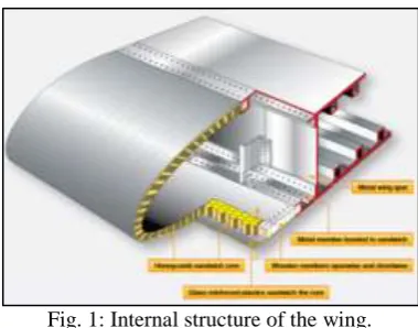
Fig. 1: Internal structure of the wing.
Reduction of mass has always presented a challenge to the Design Engineer. This led engineers to look to more efficient structures, and a patent application went through for Honeycomb manufacture, the basic idea was to use the Honeycomb as a shear web between two skins. At this stage the Adhesive Technology was not yet sufficiently developed to bond skins directly on to Honeycomb. The engineers seeing the benefits of a lightweight expanded core with integral skins, carried on with the development of using end grain balsa as a core, bonded to plywood skins. This particular sandwich or bonded structure was used extensively on the Mosquito and Vampire Aircraft. The development of Epoxy Resin made possible the bonding of aluminium skins to Aluminium Honeycomb. Since then many developments in the Honeycomb field have taken place. One of the most common materials used in Aircraft structures today is Nomex Honeycomb. One such development is the Fibrelam Panel which has a Nomex Honeycomb core with integral epoxy glass skins.
This type of construction consists of thin two facing layers separated by a core material. Potential materials for sandwich facings are aluminium alloys, high tensile steels, titanium and composites depending on the specific mission requirement. Several types of core shapes and core material have been applied to the construction of sandwich structures. Among them, the honeycomb core that consists of very thin foils in the form of hexagonal cells perpendicular to the facings is the most popular.
members. The conventional single skin structure, which is of single plates reinforced with main frames and stiffeners normally necessitates a fair amount of welding, and has a considerable length of weld seams. Further, the lighter but thinner plates employed tend to increase weld distortions that may in some cases require more fabrication work to rectify. More weld seams also mean a greater number of fatigue initiation locations as well. Honeycomb sandwich Construction, with a honeycomb core is sandwiched by two outer facing skins is better able to cope with such difficulties. Sandwich composite panels also provide added structural weight savings in the structure. It is for these reasons that the sandwich construction has been widely adopted for large weight critical structures. Honeycomb-cored sandwich composite panels have been used as strength members of satellites or aircraft, thus efficiently reducing their structural weight. In the railroad industry, passenger coaches of high-speed trains such as the TGV have been designed and fabricated using honeycomb sandwich panels. Recently, attempts to use sandwich panels as strength members of high-speed vessel hulls have also been made.
A. Sandwich Panel Loads
[image:2.595.319.531.118.196.2]An aircraft is subjected to a variety of loads during its operational life,
Fig. 2: Deflection of a sandwich panel
The deflection of a sandwich panel is made up from bending and shears components. The bending deflection is dependent on the relative tensile and compressive module of the skin materials. The shear deflection is dependent on the shear modulus of the core.
B. Honeycomb
The skin and core materials should be able to withstand the tensile, compressive and shear stresses induced by the design load. Possible failure modes in a sandwich column under axial compression include facing compressive failure, facing wrinkling, global buckling and core shear instability. Core compressive failure is unlikely because of its low stiffness and high ultimate (yield) strain. Because of the much higher stiffness of the facing material, the axial compressive stress in the facing is given by The skin to core adhesive must be capable of transferring the shear stresses between skin and core.
Fig. 3: skin compression failure
C. Panel Buckling
[image:2.595.346.512.259.343.2]The core thickness and shear modulus must be adequate to prevent the panel from buckling under end compression loads.
Fig. 4: Buckling under end compression
D. Shear Crimping
The core thickness and shear modulus must be adequate to prevent the core from prematurely failing in shear under end compression loads.
Fig. 5: shear under end compression load
E. Skin Wrinkling
The compressive modulus of the facing skin and the core compression strength must both be high enough to prevent a skin wrinkling failure.
Fig. 6: skin wrinkling
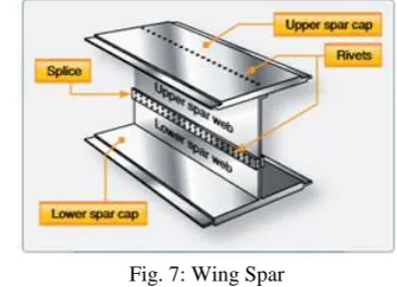
F. Wing Spars
Wing Spars are the principal structural members of the wing. Correspond to the longerons of the fuse lage. They run parallel to the lateral axis of the aircraft, from the fuselage toward the tip of the wing, and are usually attached to the fuselage by wing fittings, plain beams,
Fig. 7: Wing Spar
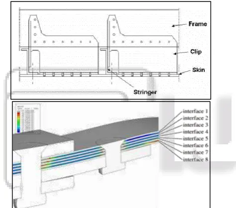
G. Monolithic
[image:2.595.333.516.584.716.2] [image:2.595.47.288.656.739.2]frame members, stringer members and skin is formed of a fiber-reinforced composite material, and where in Inter sections between the frame and stringer members include cross-plied laminate of fiber-reinforced composite material
Fig. 8: Monolithic
H. Inter rivet buckling
Inter rivet buckling is particularly challenging, since physical and geometrical non-linearity needs to be modelled together with rivet contact behaviour, in order to obtain realistic results.
Fig. 9: Numerical model of the inter rivet buckling problem
II. LITERATURE SURVEY
K.Kantha Rao, K. Jayathirtha Rao, A.G.Sarwade, M.Sarath Chandra, in there paper ‘Strength Analysis on Honeycomb Sandwich Panels of different Materials’ carried out the work that, Aluminium sandwich construction is a concept for structural design of light weight systems such as wings of aircraft. A sandwich construction, which consists of two thin facing layers separated by a thick core, offers various advantages for design of weight critical structure. Depending on the specific mission requirements of the structures, aluminium alloys, high tensile steels, titanium or composites are used as the material of facings skins. Several core shapes and material may be utilized in the construction of sandwich among them it has been known that the aluminium honeycomb core has excellent properties with regard to weight savings and fabrication costs. This paper is theoretically calculate Strength Analysis on Honeycomb Sandwich Panels of different materials
M.M. Venugopal1, S K Maharana2, K S Badarinarayan in there paper ‘Finite Element Evaluation of
Composite Sandwich Panel Under Static Four Point Bending Load’ carried out work that, the modelling approach to predict response of composite sandwich panels under static bending conditions. Different models including 2D and 3D with orthotropic material properties were attempted in advanced finite element (FE) software Ansys. Comparison of FE model predictions with experimental data on sandwich panel bending properties helped in establishing appropriate modelling approach. Analytical solutions were also used to verify the some of the mechanical properties such as bending stress and shear stress with the FEM results. For this study nomax flex core is used as a core material (thickness 15mm) and carbon fiber reinforced polymer composite (thickness 1.2mm each) is used as face sheet material. The experimental load of sandwich panels was taken and applied in steps through FEM and compared the results with experimental one at all steps.
From their work we observed that the combined Finite element modeling and experimental analysis of Carbon fibre composite sandwich panel. The core consists of Nomax honey comb structure presented in between top and bottom face laminate. The emphasis of this study is on evaluation of deflection, bending stress and shear stress response under static four point bending condition. The 2D and 3D FE model predictions correlate with experimental results of Sandwich specimen. The predicted deflection in this study is success fully matching the response of CFC sandwich panels. The 3D FE model under static loading condition is closely matching with experimental
III. METHODOLOGY
Finite element method is a numerical technique for solving engineering problems. It is most powerful analysis tool used to solve simple to complicated problems. The pre-processing stage involves the preparation of nodal coordinates & its connectivity, meshing the model, load & boundary conditions and material information for finite element models. The processing stage involves stiffness generation, modification and solution of equations resulting in the evaluation of nodal variables, run in MSC NASTRAN. The post-processing stage deals with the presentation of results, typically the deformed configurations, elemental stresses and forces.
A. Description of Problem
Sandwich panel of size 700 mm x 75 mm x 20 mm, under uniform static four point bending, tensile, compression and shear loading considered. The sandwich panel consists of 2 layers of face sheets (Glass fiber reinforced polymer composites), with ply 1 has 0.3 mm thickness & ply 2 has 0.1 mm thickness and core (Mono and Multi core) is present between top and bottom face sheets which has 19.2 mm (Mono-core) and 9.4 mm (Multi-core) thickness. The face plate laid stacking sequence is [0/90]. A sandwich panel that consists of GFRP face sheets and Nomax Flex core has been considered for the analysis
B. FEA Approach
and shear conditions. Different models including Mono-core and Multi-core were modeled in advanced finite element software
C. Four Point Bending
1) Test FEA Set-up of Bending Test Material Ply Core E
11, Mpa28800 1 E22, Mpa28800 1
E
33, Mpa28800 240 G
12, Mpa 3000 1 G23, Mpa 337 30
G
13, Mpa 3000 48 v12 0.13 0.5
v23 0.01 0.0
v
[image:4.595.46.211.106.289.2]13 0.13 0.0
Table 1: Material properties of composite sandwich panel
[image:4.595.47.288.304.760.2]D. FEM Model
Fig. 3: Modelling of composite sandwich panel
Fig. 4: Load applications and boundary condition Mono Core and Multi core
Fig. 5: Deflection plot of composite sandwich panel Mono core and Multi core
E. Observations
Displacements reduce on increasing the numbers of cores and increasing the number of ply layers adds stiffness
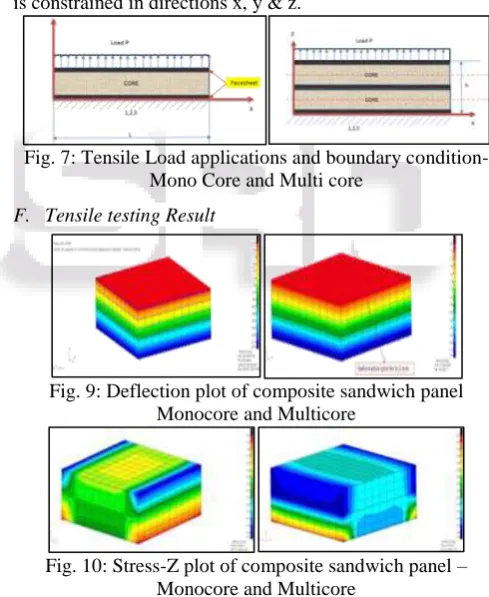
1) Tensile test
Composite sandwich panel consists of face sheet and honeycomb core. The objective of this study is to develop a modeling approach to predict response of composite sandwich panels under static face tension loading. Different models including Mono-core and Multi-core were modeled in advanced finite element analysis software.
FEA Set-up of Tension Test (Loads and BCs) For Mono core and multicore Sandwich Panel
2) Modal
Fig. 6:
[image:4.595.300.545.319.618.2]Boundary condition; tensile load of 100, 200, 300 & 400 kg is applied concentrically at the top face and the bottom face is constrained in directions x, y & z.
Fig. 7: Tensile Load applications and boundary condition- Mono Core and Multi core
F. Tensile testing Result
Fig. 9: Deflection plot of composite sandwich panel Monocore and Multicore
Fig. 10: Stress-Z plot of composite sandwich panel – Monocore and Multicore
G. Observations
The difference between the Monocore and Multicore is minimal. Multicore has 2.1% more stiffness than Mono core. The load is applied as incremental tension force from 0.01-0.03*h0/min to the specimen until the face sheet separates from the core. Here the enforced displacement is applied in increment of 0.01*h0 mm.
The maximum tensile force applied on the specimen to reach 50MPa tensile stress for Monocore is 124957 N & Multicore is 127592 N.
H. Compression
Composite sandwich panel consists of face sheet and honeycomb core. The objective of this study is to develop a modeling approach to predict response of composite sandwich panels under static compression loading. Different models including Mono-core and Multi-core were modeled in advanced finite element analysis software.
1) FEA Set-up of Compression Test (Loads and BCs) For Monocore and Multicore Sandwich Panel
I. Boundary Conditions
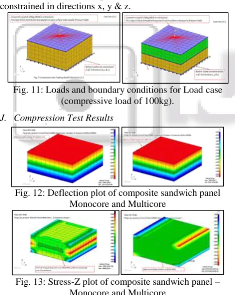
[image:5.595.329.527.261.412.2]Compressive load of 100, 200, 300 & 400 kg is applied concentrically at the top face and the bottom face is constrained in directions x, y & z.
Fig. 11: Loads and boundary conditions for Load case (compressive load of 100kg).
J. Compression Test Results
Fig. 12: Deflection plot of composite sandwich panel Monocore and Multicore
Fig. 13: Stress-Z plot of composite sandwich panel – Monocore and Multicore
K. Observations
The difference between the Monocore and Multicore is minimal. Multicore has 2.23% stiffer than Mono core, since the specimen is subjected to compressive load, core will rupture once it reaches maximum compressive strength, Compressive strength of the core is 2.1 MPa, hence the specimen will be able to take approximately 530 – 533 Kg
L. Shear Test
Composite sandwich panel consists of face sheet and honeycomb core. The objective of this study is to develop a modeling approach to predict response of composite sandwich panels under static shear loading. Different models including Mono-core and Multi-core were modeled in advanced finite element analysis software.
M. Shear Test set-up
The Shear Test composite sandwich panel of size 200 mm x 50 mm x 20 mm, under uniform static loading was considered. The sandwich panel consists of 2 layers of face sheets, with 0.4 mm thickness and core (Mono and Multi core) is present between top and bottom face sheets which has 19.2 mm (Mono-core) and 9.4 mm (Multi-core) thickness. Below figure shows Shear Test set-up and specimen dimensions
N. Shear Test set-up and specimen dimensions
The Shear test composite sandwich panel is modeled according to DIN 53 294. One end of the sandwich panel is constrained and other end is loaded diagonally as per experimental set-up. Co-ordinate 1 is created at a distance and angle as per the DIN 53 294. Cutting plates are modeled with high modulus. Rigid body elements 2 are used to transfer the load to the plates.
O. Shear Test Result
[image:5.595.45.288.334.639.2]Fig. 14: Deflection plot of composite sandwich panel– Monocore and Multicore(compression)
[image:5.595.307.548.507.694.2]P. Observations
Multicore is 7.59 % stiffer than Mono core and the displacements will remain same even after changing material Buckling analysis
IV. CONCLUSIONS
The following conclusions were given for Finite Element analysis for J-nose panel of an aircraft wing. Paper presents a combined structural analysis of glass fiber composite sandwich Monocore and Multicore panel. under static 4-point bending test, tension test, compression test and shear test, Monocore and Multicore panel consists of honey comb structure presented in between top and bottom face laminate. Emphasis of this study is on evaluation of deflection and stress, under static four point bending load, tensile load, compression load, shear load condition. Engross behaviour of mono core and multi core panel, Multicore has stiffer than Mono core. With finite element analysis results of Sandwich
specimen. Displacements reduce on increasing the numbers of cores. Due to increasing in number of ply layers which adds to stiffness
REFERENCE
[1] M.M. Venugopal, S K Maharana, K S Badarinarayan, “Finite Element Evaluation of Composite Sandwich Panel Under Static Four Point Bending Load”,JEST-M, Vol. 2, Issue 1, 2013 .
[2] Belouettar and Abbadi, “Experimental investigation of static and fatigue behavior of composites honeycomb materials using four point bending tests”, Composite Science Technology 2003; 70:2556–64.
[3] Meyer-Piening H-R, “Remarks on higher order sandwich stress and deflection analysis”. In: Olsson K-A, Reichard RP, editors. Proceedings of the first international Conf on Sandwich Constructions 1989 P107–27.
[4] Kemmochi and Uemura, “The stress distribution in sandwich beams made of three kinds of photo elastic materials under four-point bending”. Journal of Mechanics, 2356-23; Jun 2000.
[5] Juli F Davalos, and Pizhongqiao, “modeling and characterization of fiber reinforced plastic honeycomb sandwich panel for highway bridge applications”. Mechanics of materials 1998; 5642-13 material in three point bending Part 1.Static tests” Journal of composites 2001; 4281-14.
[6] A Bezazi, and A El Mahi, “Experimental analysis of behavior and damage of sandwich composite”.
[7] Engin M, Reis and Sami.H.Rizekalla “Material characteristics of 3D FRP sandwich panel”. 3rd edition oxford press.